LEO-Augmented GNSS Based on Communication Navigation Integrated Signal

Abstract
1. Introduction
1.1. Restrictions on Signal Parameters
- (a)
- Direct Sequence Spread Spectrum (DSSS) and BPSK are considered for the navigation signal.
- (b)
- Assume that the orbit altitude is 24,000 km for medium Earth orbit (MEO). Then, the power deterioration difference for MEO and LEO will be 20 × log(24000/780) = 29.76 dB. This means that when the launch power of the signal is the same, the received power of signal from LEO will be 29.76 dB higher than that from MEO for receivers on the ground. In the following, the CN0 difference is assumed to be 30 dB for simplicity.
- (c)
- The power of each unit band is assumed to be identical, which means that every unit band gets 1/252 of the total power.
- (d)
- The CN0 of GNSS signals mainly falls in 30–50 dBHz in urban areas. Therefore, the analysis assumes that the highest CN0 of the LEO signal is 80 dBHz.
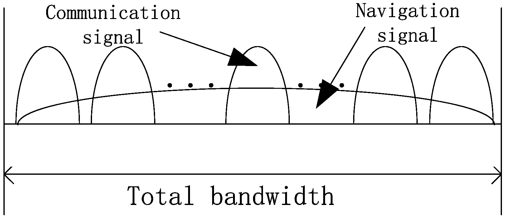
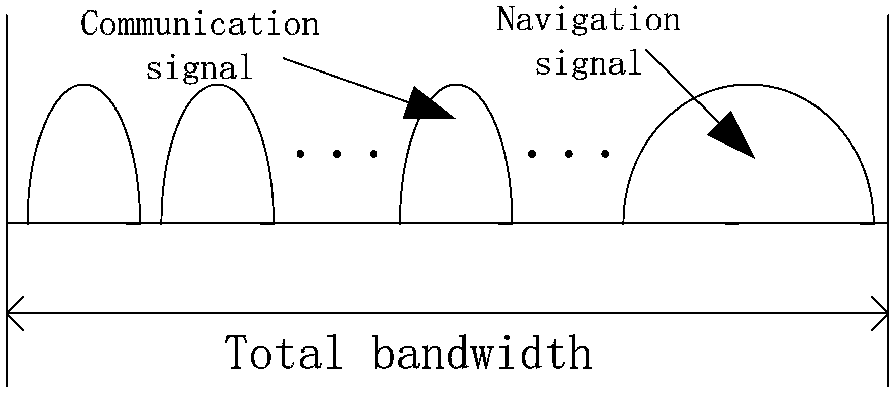
1.2. Methods for Signal Integration
2. Performance of the Navigation Signal
2.1. Pseudorange Accuracy
- : ,
- : ,
- : ,
- : ,
- (1)
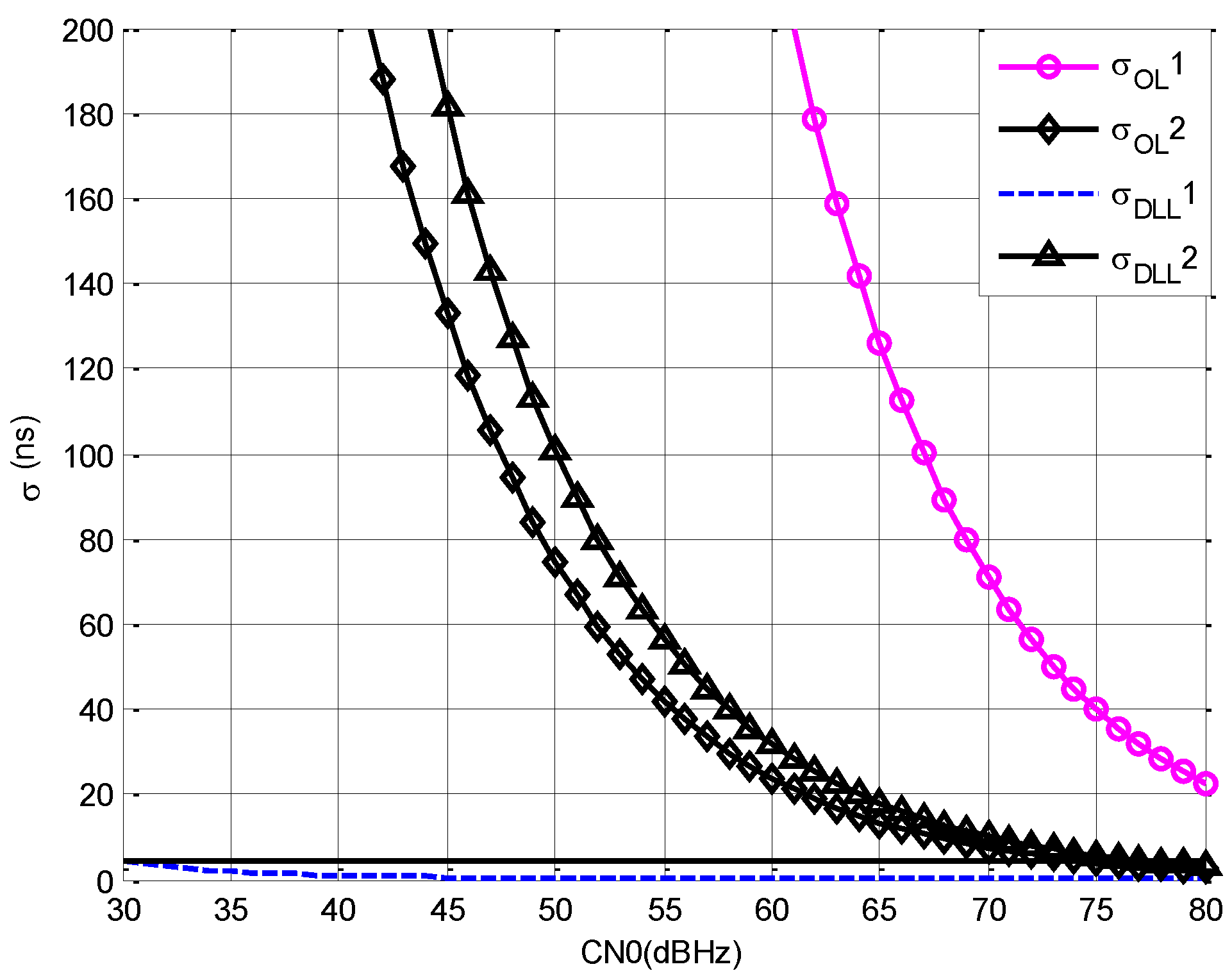
- Comparing with and , it can be seen that with the increment of , decreases for open loop estimation. However, the advantage of open loop estimation over DLL is low when the bandwidth is the same.
- (2)
- Comparing with , it can be seen that the accuracy of DLL is better than open loop estimation even though is lower than D.
- (3)
- Comparing with , it can be seen that the increment of causes great decrement of , and, when CN0 is 77 dBHz, is about the same with when CN0 is 30 dBHz.
2.2. Doppler Accuracy
- : :
- : :
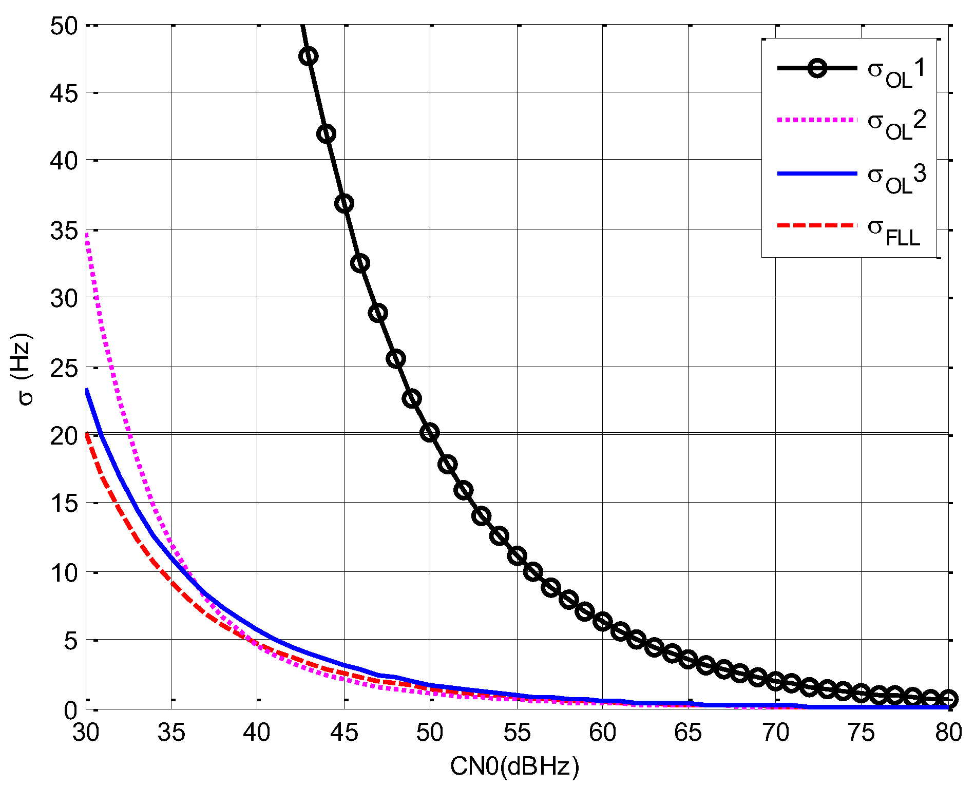
- (1)
- Comparing with , it can be seen that with the increment of , decreases greatly.
- (2)
- Comparing with , it can be seen that the effect of to is not the same during the whole CN0 range. When CN0 is lower than 37 dBHz, shows better performance, and when CN0 is higher than 37 dBHz, shows better performance. The optimal choice of is another optimization objective and it is not analyzed in this paper.
- (3)
- Comparing with the others, it can be seen that when is the same, FLL is better than open loop estimation and, if is increased, the accuracy of open loop estimation is close to FLL.
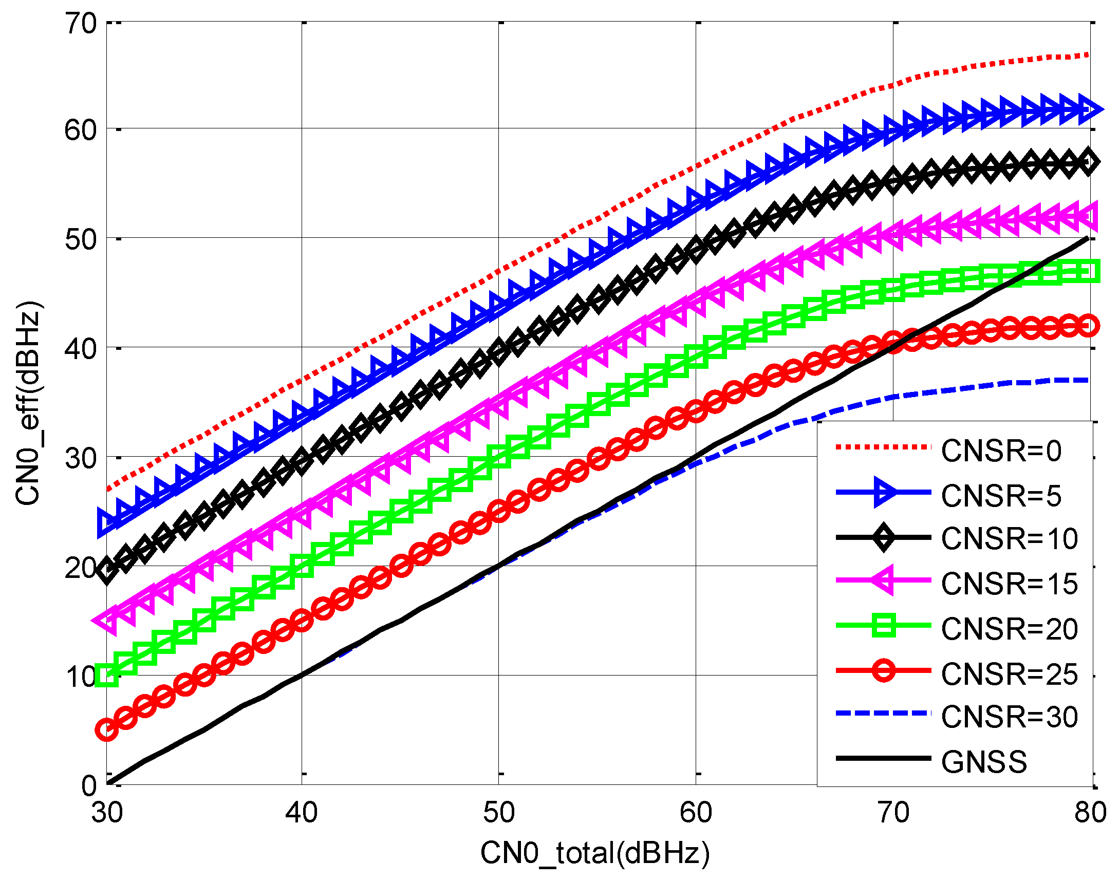
2.3. CN0 of the Navigation Signal
- (a)
- When is below 60 dBHz, increases almost linearly with the increment of . When is above 70 dBHz, the effective PSD of the communication signal grows to be larger than thermal noise. Therefore, the increment rate of CN0eff goes down.
- (b)
- When is fixed, decreases with the increment of . When is lower than 15 dB, holds advantage over the CN0 of GNSS signals for the whole range. Therefore, the value of should be lower than 15 dB.
3. Performance of Communication Signal
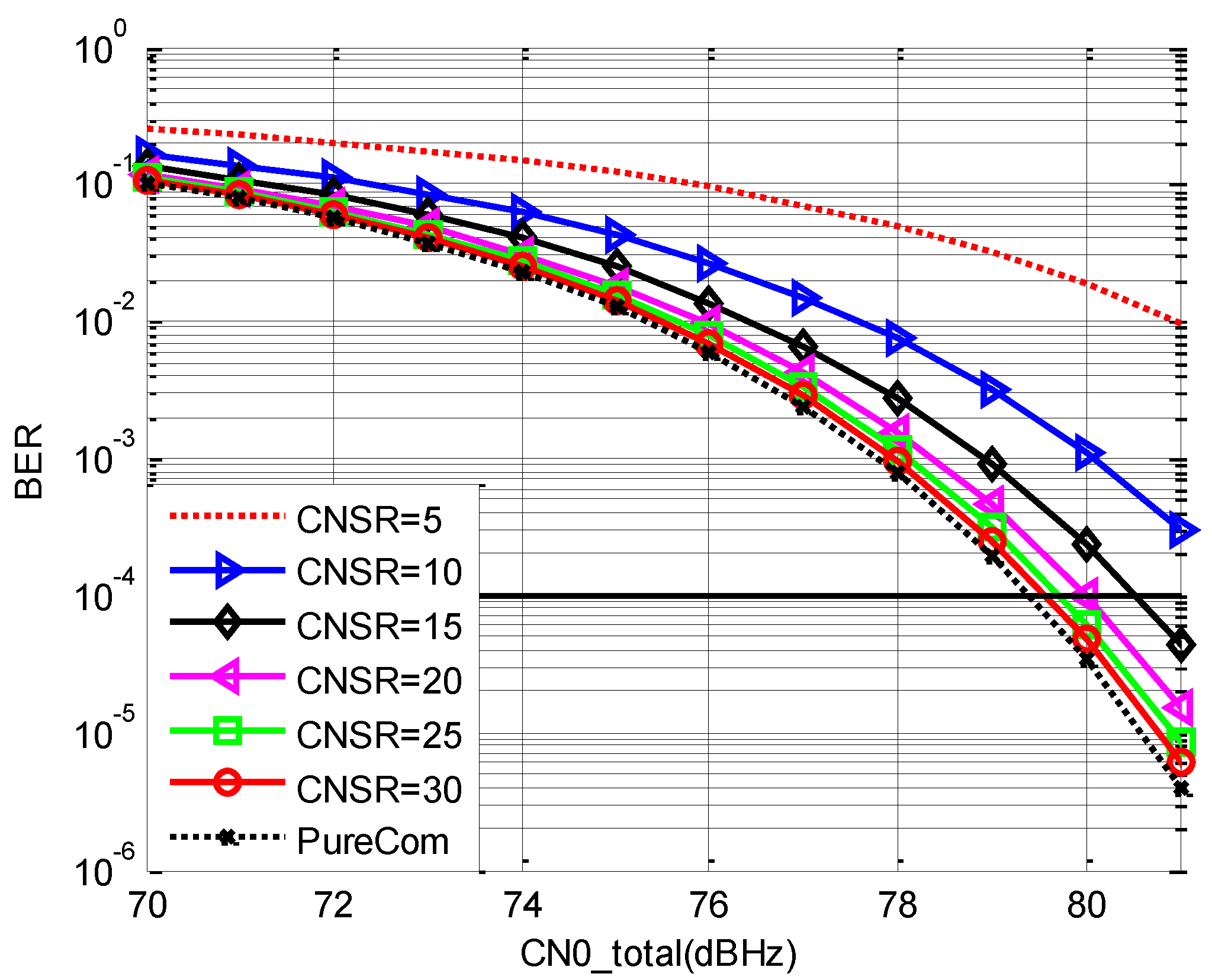
3.1. BER Performance
3.2. Communication Capacity
4. Comprehensive Comparison
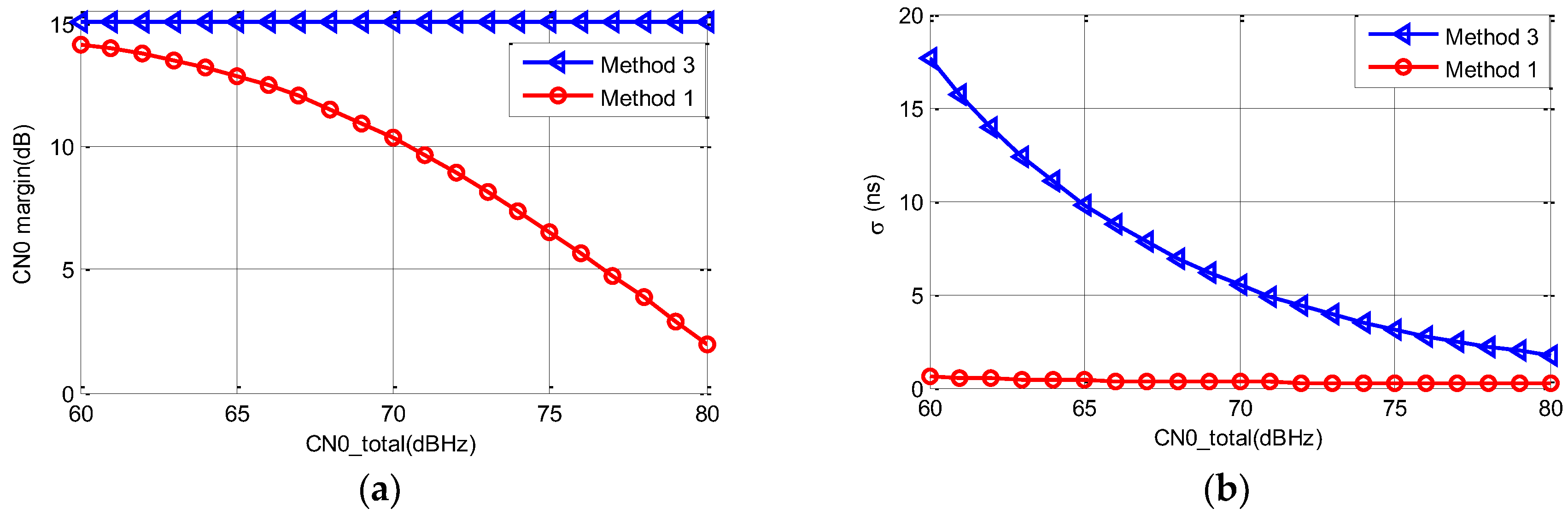
4.1. Comparison of Methods 1 and 3
4.2. Comparison of Methods 2 and 3
4.3. Summary
5. Conclusions
Author Contributions
Funding
Conflicts of Interest
References
- Iridium NEXT: A Global Effort to Launch the Future of Global Communications. Available online: http://www.iridium.com (accessed on 27 October 2019).
- Zhang, H.; Wang, M.C.; Cui, W.Z. Satellite Comunication, 1st ed.; Beijing Institute of Technology Press: Beijing, China, 2018. (In Chinese) [Google Scholar]
- Meng, Y.; Bian, L.; Han, L.; Lei, W.; He, M. A Global Navigation Augmentation System Based on LEO Communication Constellation. In Proceedings of the European Navigation Conference, Gothenburg, Sweden, 14–17 May 2018. [Google Scholar]
- Meng, Y.; Bian, L.; Han, L.; Lei, W.; Yan, T.; He, M.; Li, X. A global navigation augmentation system based on LEO communication constellation. J. Terahertz Sci. Electron. Inf. Technol. 2019, 17, 65–71. [Google Scholar]
- Wang, L.; Chen, R.; Li, D.; Zhang, G.; Shen, X.; Yu, B.; Wu, C.; Xie, S.; Zhang, P.; Li, M.; et al. Initial Assessment of the LEO Based Navigation Signal Augmentation System from Luojia-1A Satellite. Sensors 2019, 18, 3919. [Google Scholar] [CrossRef] [PubMed]
- Joerger, M.; Gratton, L.; Pervan, B.; Cohen, C.E. Analysis of Iridium-augmented GPS for floating carrier phase positioning. Navigation 2010, 57, 137–160. [Google Scholar] [CrossRef]
- Rabinowitz, M.; Parksinson, B.W.; Gromov, K. Architectures for Joint GPS/LEO Satellite Carrier Phase Receivers Designed for Rapid Robust Resolution of Carrier Cycle Ambiguities on Mobile Platforms. In Proceedings of the 13th International Technical Meeting of the Satellite Division of The Institute of Navigation, Salt Lake City, UT, USA, 19–22 September 2000. [Google Scholar]
- Tian, S.; Dai, W.; Liu, R.; Chang, J.; Li, G. System Using Hybrid LEO-GPS Satellites for Rapid Resolution of Integer Cycle Ambiguities. IEEE Trans. Aerosp. Electron. Syst. 2014, 50, 1774–1785. [Google Scholar] [CrossRef]
- David, W.B. iGPS: Integrated Nav & Com Augmentation of GPS; Boeing Defense Space & Security: Berkeley, MS, USA, 2010. [Google Scholar]
- He, T.; Ma, Z. Proposed OFDM Modulation for Future Generations of GNSS Signal System. J. Navig. 2016, 69, 971–990. [Google Scholar] [CrossRef][Green Version]
- Diez, J.; de Castro, D.; Palomo, J.M.; Tossaint, M. Integrated Navigation and Communication System based on OFDM. In Proceedings of the 5th ESA Workshop on Satellite Navigation Technologies and European Workshop on GNSS Signals and Signal Processing, Noordwijk, The Netherlands, 8–10 December 2010. [Google Scholar]
- Pratt, S.R.; Raines, R.A.; Fossa, C.E.; Temple, M.A. An Operational and Performance Overview of the Iridium Low Earth Orbit Satellite System. IEEE Commun. Surv. 1999, 2, 2–10. [Google Scholar] [CrossRef]
- Huang, X.; Zhao, X.; Zhu, X.; Ou, G. MC-BOC: A New Interoperable Modulation and Performance Analysis for BeiDou B1 Signal. In Proceedings of the China Satellite Navigation Conference (CSNC), Beijing, China, 22–25 May 2018; pp. 211–221. [Google Scholar]
- Deng, Z.; Yuan, X.; Yu, Y. A Novel Pseudo Code Ranging Method for High Accurate Cellular Positioning Receiver. Adv. Inf. Sci. Serv. Sci. 2013, 15, 1068–1075. [Google Scholar]
- Elliott, D.; Hegarty, C. Understanding GPS: Principles and Applications, 2nd ed.; Publishing House of Electronics Industry: Beijing, China, 2012. (In Chinese) [Google Scholar]
- Ruan, H.; Li, J.; Zhang, L.; Long, T. Adaptive Correlation Space Adjusted Open Loop Tracking Approach for Vehicle Positioning with Global Navigation Satellite System in Urban Areas. Sensors 2015, 15, 21581–21612. [Google Scholar] [CrossRef] [PubMed]
- Tang, X.; Falletti, E.; Presti, L. Fine Doppler Frequency Estimation in GNSS Signal Acquisition Process. In Proceedings of the 6th ESA Workshop on NAVITEC, Noordwijk, The Netherlands, 5–7 December 2012; pp. 1–6. [Google Scholar]
- Lin, H.; Tang, X.; Ou, G. An Open Loop with Kalman Filter for Intermittent GNSS Signal Tracking. IEEE Commun. Lett. 2017, 15, 2634–2637. [Google Scholar] [CrossRef]
- Hu, Y.; Song, M.Z.; Dang, X.Y. A Method for the Navigation Satellite Signal Enhancement Based on the Signal Retransmission by the Communication Satellite. J. Electron. Inf. Technol. 2015, 3, 24. [Google Scholar]


| Method 1 | Method 2 | Method 3 | |
|---|---|---|---|
| Pseudorange precision | High | Low | Medium |
| Doppler precision | High | Medium | High |
| CN0 margin | Medium | High | High |
| Positioning method | Pseudorange/Doppler/Carrier phase | Pseudorange/Doppler | Pseudorange/Doppler/Carrier phase |
| Communication loss | Low | Low | Medium |
© 2019 by the authors. Licensee MDPI, Basel, Switzerland. This article is an open access article distributed under the terms and conditions of the Creative Commons Attribution (CC BY) license (http://creativecommons.org/licenses/by/4.0/).
Share and Cite
Wang, L.; Lü, Z.; Tang, X.; Zhang, K.; Wang, F. LEO-Augmented GNSS Based on Communication Navigation Integrated Signal. Sensors 2019, 19, 4700. https://doi.org/10.3390/s19214700
Wang L, Lü Z, Tang X, Zhang K, Wang F. LEO-Augmented GNSS Based on Communication Navigation Integrated Signal. Sensors. 2019; 19(21):4700. https://doi.org/10.3390/s19214700
Chicago/Turabian StyleWang, Lei, Zhicheng Lü, Xiaomei Tang, Ke Zhang, and Feixue Wang. 2019. "LEO-Augmented GNSS Based on Communication Navigation Integrated Signal" Sensors 19, no. 21: 4700. https://doi.org/10.3390/s19214700
APA StyleWang, L., Lü, Z., Tang, X., Zhang, K., & Wang, F. (2019). LEO-Augmented GNSS Based on Communication Navigation Integrated Signal. Sensors, 19(21), 4700. https://doi.org/10.3390/s19214700