An indexed metrology platform is proposed by Brau et al. [
26] as an auxiliary instrument for use in calibration and verification procedures for portable coordinate measuring instruments. The methodology developed in this work using the indexed metrology platform tries to improve the verification procedures for AACMMs in terms of the testing time and working space required compared to the procedures described in the standards [
4,
5,
6]. This new procedure allows the generation of an unlimited number of virtual reference distances through the platform’s mathematical model, thereby minimizing the number of tests positions required of the physical gauge during verification. Alternative to conventional procedures, the reduction in the testing positions is achieved by settling the calibrated gauge in a fixed position in the AACMM’s working volume and measuring the gauge with the AACMM assembled on the IMP from the six platform rotating positions distributed at 60° each. In this way, when the platform rotates to a new position, which permits the AACMM to measure the same point in the ball bar gauge, a new working volume of the instrument is evaluated.
The design of the platform is based on two hexagonal steel platforms, the upper and lower platforms. The upper, or mobile platform, rotates around the lower platform and is the one on which the portable coordinate measuring instrument is fixed. The lower platform is located in the base of the IMP. The overall platform includes six capacitive sensors and targets with nanometer resolution, which are located in the lower and upper platforms, respectively. These sensors enable the IMP to precisely measure the orientation and position of the upper platform with respect to the lower platform. Three of the sensors are located axially, and the other three are tangentially placed with respect to the rotation axis of the IMP. The capacitive sensor probe model used is a C5-E from vendor Lion Precision, with a measuring range of 100 µm for an output voltage from 10 to −10 V and an operational range from 100 to 200 µm.
An estimation of the measurement uncertainty of the platform was developed in a previous work by the authors [
27] using the Monte Carlo method. Similar approaches developing an AACMM uncertainty model using a multi-level Monte Carlo method can be found in [
28,
29]. In our work, the input variables of the model were first identified, and the
n-homogeneous transformation matrices (XYZABC) were considered the output variables of the IMP’s mathematical model.
Table 1 shows the IMP position and orientation uncertainty for a given platform position and point measured. Two reference calibrated distances were defined, d12 = 100.8024 mm and d15 = 399.9613 mm, in order to calculate the distance error value given as the difference between the distance in the Monte Carlo simulation and the calibrated distance value in the ball bar. The
Table 2 presents the uncertainty of the IMP in a distance measurement obtained as a result of running the Monte Carlo simulation over 10,000 iterations.
2.1. Kinematic Model Integration
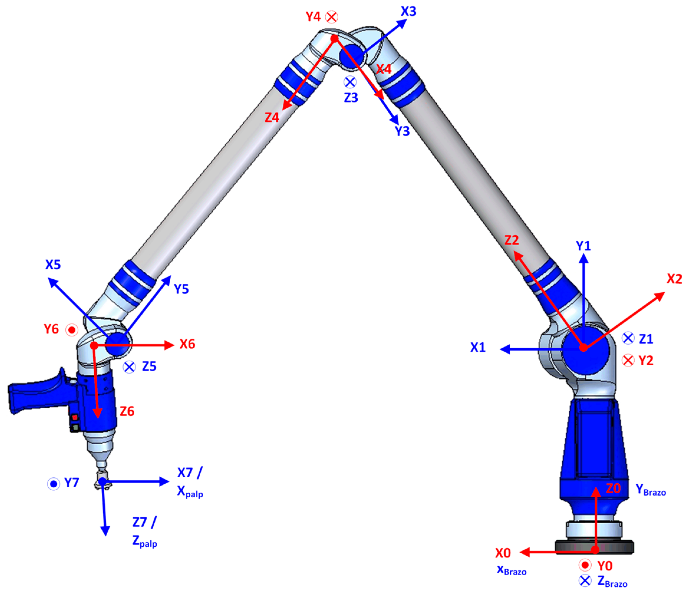
The development of the verification procedure starts with the construction of the kinematic model of the AACMM and the indexed metrology platform, defining the geometric transformations, the location of the coordinate reference systems and the initial nominal geometric parameters of the model. The integration of the AACMM’s kinematics and the platform mathematical model enables the expression of a point captured with the AACMM in the global platform’s coordinate reference system (RS Global) located in the lower platform. By using the mathematical model of the platform, it is possible to calculate a homogenous transformation matrix (HTM) that will allow the change of the coordinate reference systems required. The kinematic model of the AACMM used in this work, Faro Platinum, is based on the Denavit–Hartenberg model (D-H) [
30]. Using the D-H model, the coordinates of a point measured with the AACMM in terms of the angles and distance values of the kinematic chain can be obtained. The kinematic model according to the D-H model is shown in
Figure 1 and includes a global coordinate reference system (x
0, y
0, z
0) situated on the base of the arm, one coordinate reference system per each rotary joint and the last coordinate reference system located in the stylus (x
7, y
7, z
7) corresponding to the rotation of the wrist of the AACMM.
Once the coordinate reference systems of the model are defined, the next step is to determine the geometric parameters of the model,
di, ai, θi and
αi. The initial values of the geometric parameters of the D-H model, i.e.,
di, ai, θi and
αi, are included in
Table 3.
The notation used to express a point measured with the AACMM in the AACMM’s global coordinate reference system with the origin in the arm (x
0, y
0, z
0), initially expressed in the stylus reference system (x
palp, y
palp, z
palp), in terms of
θ,
and
d, is defined by Equation (1):
where
0T
7 is the homogeneous transformation matrix (HTM) expressed in terms of the product of successive coordinate transformation matrixes
i−1A
i,
θ and
are values obtained from the angular encoders and
d is the measured distance, as shown in Equation (2):
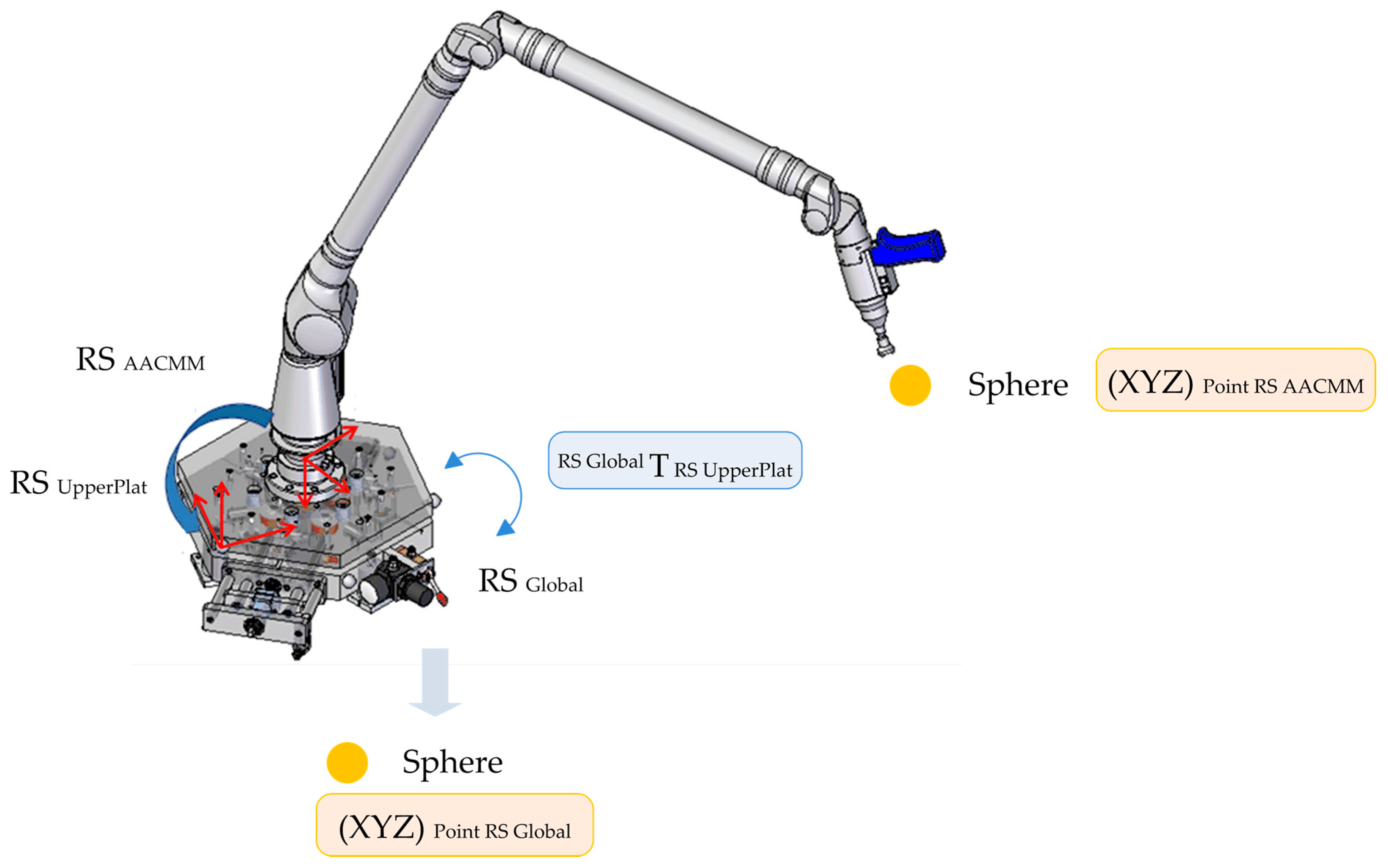
The indexed metrology platform model uses the optimum platform’s geometric parameters found during its calibration and the readings from the capacitive sensors captured for each point measured with the AACMM in the verification procedure. For each point measured, a single homogeneous transformation matrix (HTM) is generated. This matrix allows the transformation from the upper platform reference system (RS
UpperPlat) to the global reference system (RS
Global) located in the lower platform for the six platform positions. The notation used to express a point measured with the AACMM with its coordinates in the AACMM’s coordinate reference system (RS
AACMM) into the fixed global coordinate reference system of the lower platform (RS
Global) for each of the six positions of the platform is simplified and shown in Equation (3) and is calculated via the platform’s mathematical model. This concept is graphically explained in
Figure 2.
2.2. Verification Procedure Methodology
The AACMM model used in the testing is a Faro Platinum arm with seven axes, 2.4 m measuring range, a volumetric accuracy of ±0.043 mm and a single point repeatability of 0.030 mm. A ball bar gauge with a length of 1400 mm was selected as the calibrated gauge and was located in different poses in the AACMM’s working volume. The definition of the reference distances to measure together with their distribution in the working volume of the arm was done taking as a reference the volumetric performance evaluation included in the ASME B89.4.22-2004 [
4] standard. The following parameters were considered in the definition of the positions: the gauge length (short 800 mm/long 1400 mm), the ball bar gauge inclination (horizontal, vertical and 45°), the ball bar gauge direction with respect to the AACMM (radial or tangential for horizontal dispositions and 45°), the ball bar gauge distance to the center of the working volume, the height of the ball bar and the octants affected. The main target is to test as many possible arm angle combinations as possible in the selected verification testing positions. In this work, a 45° diagonal position tangential to the AACMM, known as Diag45 upwards, which covered two octants of the working volume of the arm, was used as a reference and was measured with the AACMM from all of the platform positions (1–6). Five spheres were measured, capturing nine points per sphere and calculating the distances between the spheres’ centers and their deviations in length versus the calibrated distances, as shown in
Figure 3.
The physical gauge is measured with the AACMM assembled on the IMP from all of the rotating positions of the platform (1–6). Each time the platform rotates 60° to a new position, the AACMM measures the same physical gauge from a different platform position, which is equivalent to measuring six physical gauges located in different locations in the AACMM’s working volume from the same platform position. The measurements of the same gauge carried out from the six platform positions define the measured points, resulting in six measured gauges. The Euclidean distances between the points measured are known as measured distances and are used as a parameter in the volumetric performance evaluation of the AACMM. In parallel to the measurement of the points, the values of the capacitive sensors assembled in the indexed metrology platform are captured for each measurement and platform position. These captures are used to obtain a single homogenous transformation matrix per point measured that expresses a point captured by the AACMM in a global coordinate reference system located in the lower platform, as explained in
Section 2.1.
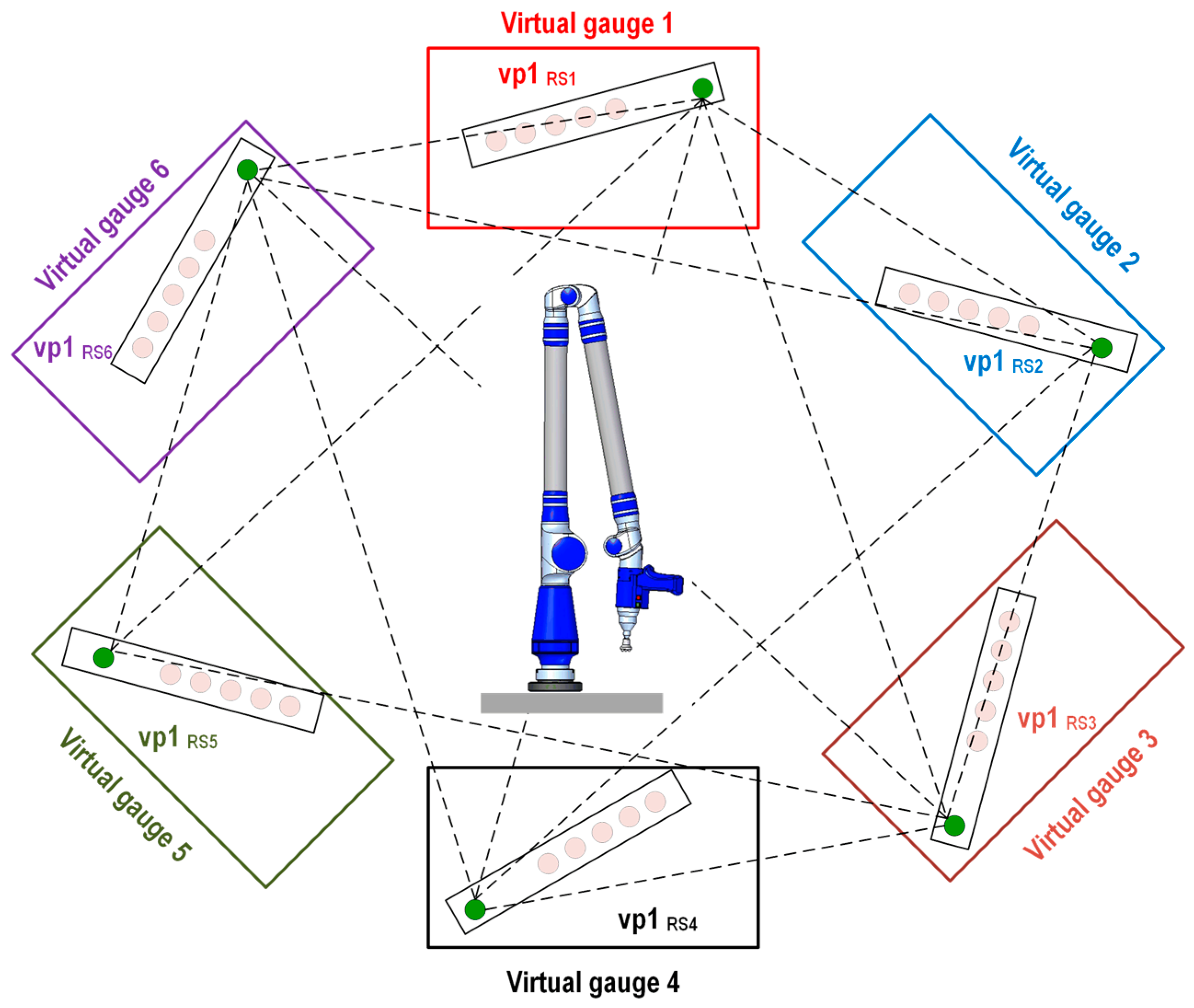
If we take as a reference the measurements from the gauge done with the AACMM from a selected platform position and because we know with high accuracy the position of the upper platform with respect to the lower platform, the generation of the virtual gauge using the IMP model is based on applying the known rotation angle of the platform to the measured ball bar gauge and being able to generate virtual gauges rotated at 60°/120°/180°/240°/300° from the measured gauge in the selected position of the platform. For example, if we consider the gauge measured in platform position number 1 to be a reference, known as measured gauge 1, it is possible to use the mathematical model of the indexed metrology platform to generate a set of virtual points that will integrate virtual gauge 1, corresponding to the indexed metrology platform’s position number 1. This procedure is repeated successively for the six rotating platform positions, creating the six virtual gauges, as shown in
Figure 4. The six virtual gauges are affected by the 60° rotation of the platform from one position to the next. In this work, it is taken as a reference, the coordinate reference system corresponding to platform position 1 which is known as the AACMM reference system 1 (RS
1). Therefore, a point measured from the AACMM reference system 1 (RS
1) will have the same coordinates as its equivalent virtual point expressed in the AACMM reference system 1 (RS
1).
Here, we explain the procedure to generate a virtual point via the mathematical model of the IMP. The procedure starts with the measurement of a point, point 1, on the ball bar gauge with the AACMM assembled on the indexed metrology platform from platform position 1. The coordinates of this point 1 are expressed in AACMM reference system 1, RS1. The second step is rotating the platform 60° from position 1 to position 2 and to measure again from this platform position 2, the point 1. The coordinates of this point are now expressed in AACMM reference system 2, RS2. We could say that this second measurement is equivalent to measuring a virtual point rotated 60°, known as point 1’ from platform position 1, with its coordinates expressed in AACMM reference system 1, RS1. The virtual point is thus affected by the rotation of the platform from platform position 1 to platform position 2.
Taking as a reference one point measured using platform position 1, where the measured and virtual points have the same coordinates in the virtual gauge 1 and expressing these coordinates in AACMM reference system 1 (RS1), it is possible to generate a virtual point in virtual gauge 2 through the indexed metrology platform’s mathematical model. In this calculation, the translational and rotational components of the homogeneous transformation matrix, which changes from platform position 1 to platform position 2, are considered, assuming that the coordinates of the virtual point are expressed in the AACMM reference system 1 (RS1), as shown in Equation (4).
The T matrix is a homogeneous transformation matrix that provides a change in the coordinates from AACMM reference system 1 (RS
1), corresponding to the virtual point in virtual gauge 1, to AACMM reference system 2 (RS
2)
, where the new virtual point in virtual gauge 2 is created by the rotation of the platform. The main difference is the assumption that the new virtual point generated in virtual gauge 2 will have its coordinates expressed in the AACMM reference system 1 (RS
1), as though the AACMM were measured from position 1 of the platform, as explained in
Figure 5.
The homogeneous transformation matrix T is expressed in Equation (5),
where
: AACMM reference system 2 to upper platform reference system homogeneous transformation matrix.
: AACMM reference system 1 to upper platform reference system homogeneous transformation matrix.
: Upper platform reference system to global platform reference system homogeneous transformation matrix. This matrix is generated per each measured point out of the values of the capacitive sensors assembled in the indexed metrology platform.
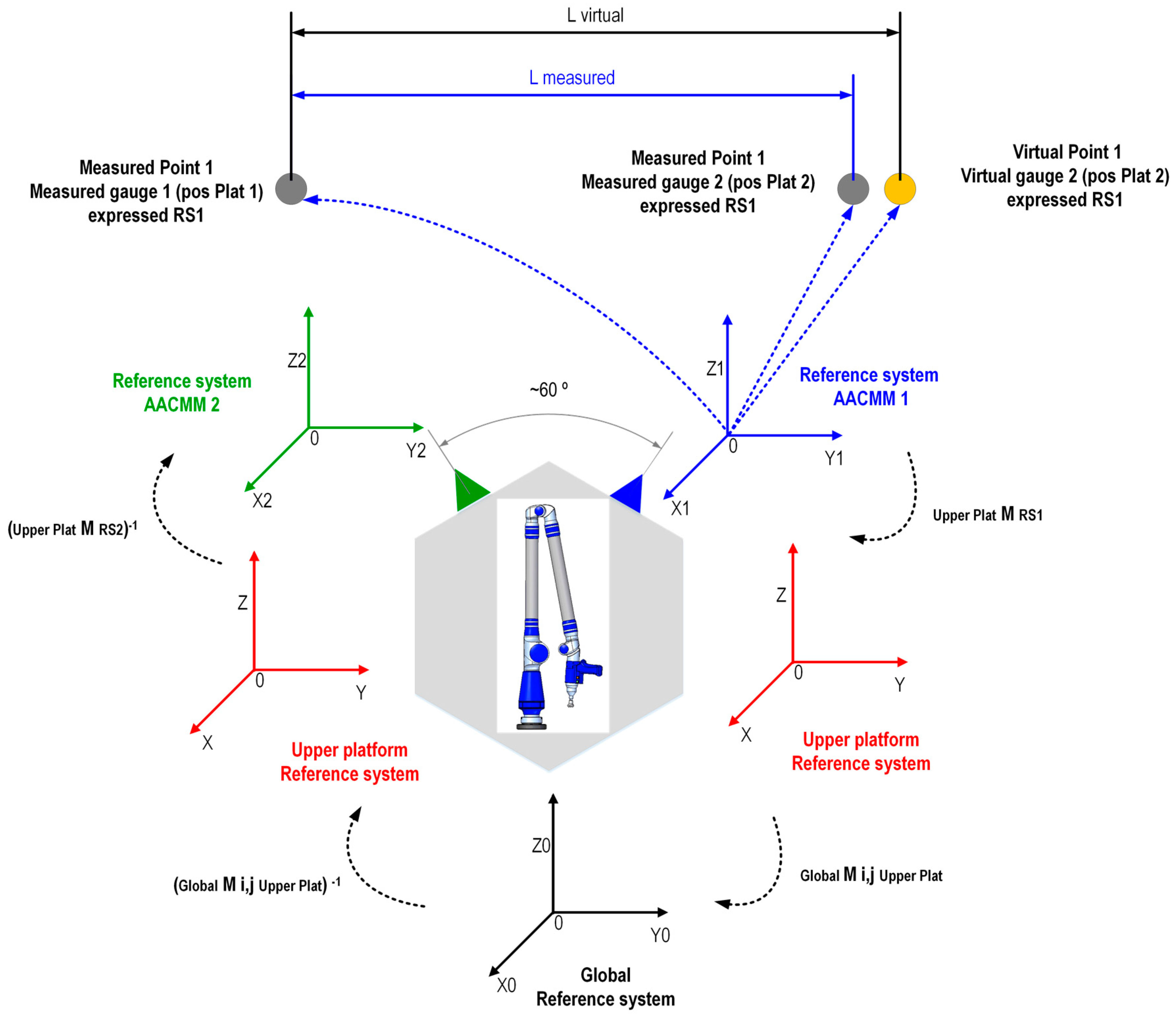
The next concept to be developed is the generation of the virtual distance between the virtual points. With this procedure, it is possible to create an unlimited number of Euclidean distances of different lengths between virtual points located either in the same or in different virtual gauges. Taking platform position 1 as a reference, the concepts of measured distance and virtual distance are shown in
Figure 5. The measured distance is defined as the Euclidean distance between point 1 measured from platform position 2, assuming that its coordinates are expressed in AACMM reference system 1 (RS
1), and the coordinates measured from platform position 1 and expressed in AACMM reference system 1 (RS
1). The virtual distance is defined as the Euclidean distance between virtual point 1 generated in virtual gauge 2, assuming that its coordinates are expressed in AACMM reference system 1 (RS
1), and virtual point 1, with its coordinates expressed in AACMM reference system 1 (RS
1). It is necessary to note that the coordinates of virtual point 1 in virtual gauge 2 and the coordinates of measured point 1 from platform position 2, both of which are expressed in AACMM reference system 1 (RS
1), will not be exactly equal due to the error in the indexed metrology platform. This deviation in the coordinates between the measured and virtual points is translated into a distance error D
i between the virtual distance L
Virtual and the measured distance L
Measured.
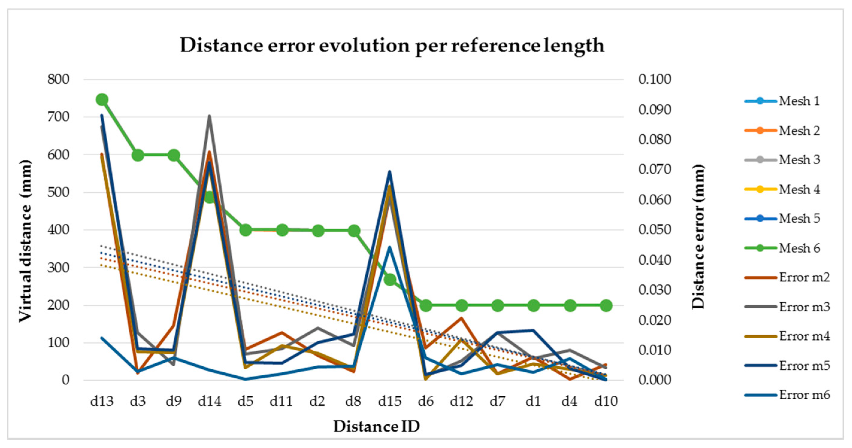
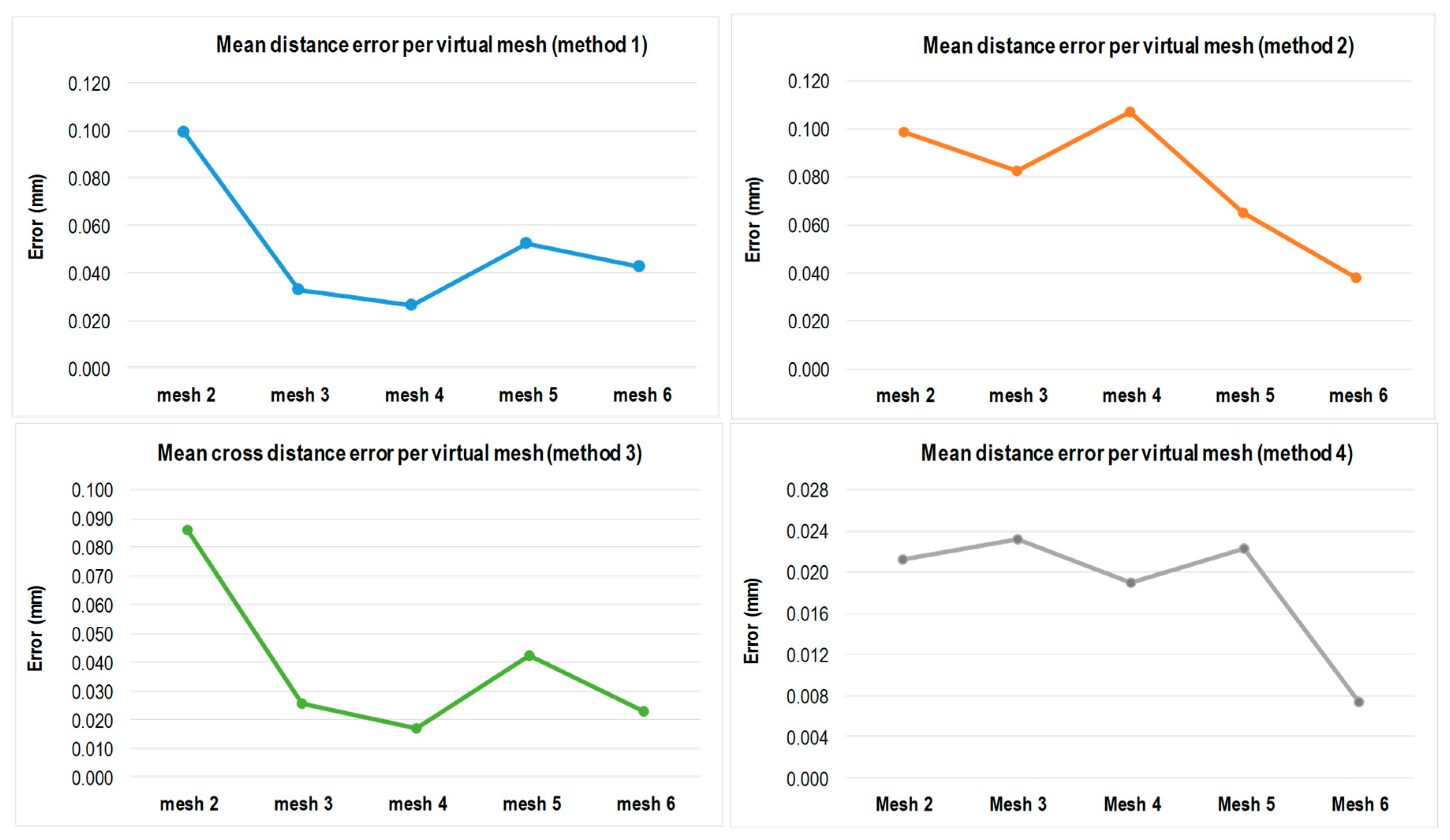
To evaluate the volumetric performance of the AACMM in its working volume using the virtual distances method, three parameters are selected. First, we examine the maximum distance error among all positions of the platform, the range of the distance errors and a mean distance error. Four evaluation alternatives using the virtual distance technique were developed in this work and are explained, considering AACMM reference system 1 (RS1) to be the reference system for the procedure.
2.2.1. Evaluation Method 1: Virtual Distances among Virtual Points in Gauge 1 and Equivalent Virtual Points in Gauges (2–6)
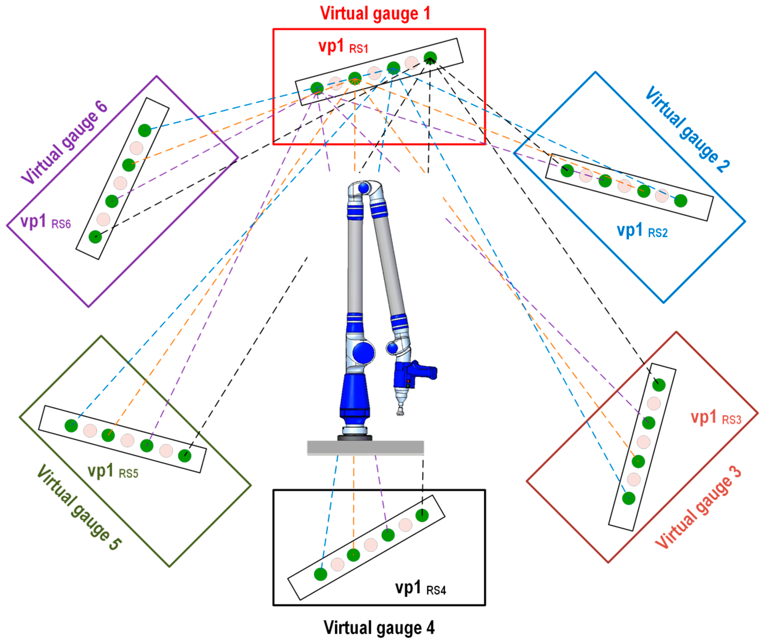
The first evaluation method targets the definition of a virtual distance based on distance calculations among the center coordinates of the four virtual balls in virtual gauge 1 and their coordinates in the other virtual gauges (2–6). This method enables the generation of virtual distances of different lengths that are larger and greater in number than those that can be defined using a physical ball bar gauge. A total of 20 virtual distances are calculated, as shown in
Figure 6, with their graphical representations shown as six example virtual points 1, vp1
RS1–vp1
RS6, generated in the corresponding virtual gauges (1–6). The Euclidean distance between virtual point 1 (vp1
RS1) located in virtual gauge 1 is used as a reference. The remainder of the virtual points (vp1
RS2–vp1
RS6) generated in virtual gauges 2 to 6 may be obtained using Equation (6):
where
Di,j is the Euclidean distance between the virtual point
j in each of the
i virtual gauges, and the virtual point
j in virtual gauge 1 with their coordinates expressed in AACMM reference system 1 (RS
1).
2.2.2. Evaluation Method 2: Virtual Hexagon, Evaluation through Virtual Distances among Virtual Points in Consecutive Gauges
The virtual distances hexagon method focuses on evaluating the instrument’s error at different heights and rotation angles because of the platform’s rotation. Four virtual hexagons are generated depending on the virtual point’s height in the virtual gauge. The definition of the virtual distance is based on the generation of virtual distances between the coordinates of the equivalent virtual balls’ centers located in consecutive gauges, which define the virtual hexagons at different heights. A total of 20 virtual distances are defined, and a representation of the virtual distances generated in the six virtual gauges considering virtual point 1 (vp1) as an example is shown in
Figure 7. The Euclidean distances between the virtual points situated in virtual gauge
i and the equivalent virtual points located in the consecutive virtual gauges according to the positions of the platform (1–6) are shown in Equation (7):
where
Di,j is the Euclidean distance between the virtual point
j in each of the
i virtual gauges, and the virtual point
j in the next virtual gauge
i + 1, with their coordinates expressed in AACMM reference system 1 (RS
1).
2.2.3. Evaluation Method 3: Evaluation through Crossed Virtual Distances among Virtual Points in Different Virtual Gauges
The following evaluation method is based on the generation of crossed virtual distances among virtual balls located in the six virtual gauges. In this way, 20 crossed distances among the four different spheres in different virtual gauges are evaluated, as shown in
Figure 8. The Euclidean distances between virtual points located in virtual gauge 1, which is used as a reference, and the rest of the virtual points generated in virtual gauges (2–6) according to the positions of the platform are listed in
Table 4.
2.2.4. Evaluation Method 4: Evaluation by Horizontal, Vertical and Diagonal Virtual Distances Using Virtual Gauges (1–6)
The last evaluation method is based on virtual distances defined among virtual balls located in the same virtual gauge or mesh of virtual points. Two new ball bar gauge measured positions were included in this method, following the recommendations in the standards [
4,
5,
6]: one additional diagonal position at a 45° inclination (Diag45 down) and a horizontal position (Horizontal). With these two new poses, we gain flexibility in the distance definition, which permits the generation of horizontal, vertical and diagonal virtual distances among the spheres. From these, 15 virtual distances classified according to their position (horizontal, vertical or diagonal) are created, as shown in
Table 5 and
Figure 9. Virtual gauge 1 is taken as an example, but the same virtual distances are replicated in virtual gauges 2 to 6, which are used to generate the complete virtual distance scenario for this evaluation method.


