Frame Coating of Single-Walled Carbon Nanotubes in Collagen on PET Fibers for Artificial Joint Ligaments

 ,
,  , , , , ,
Abstract
1. Introduction
2. Results
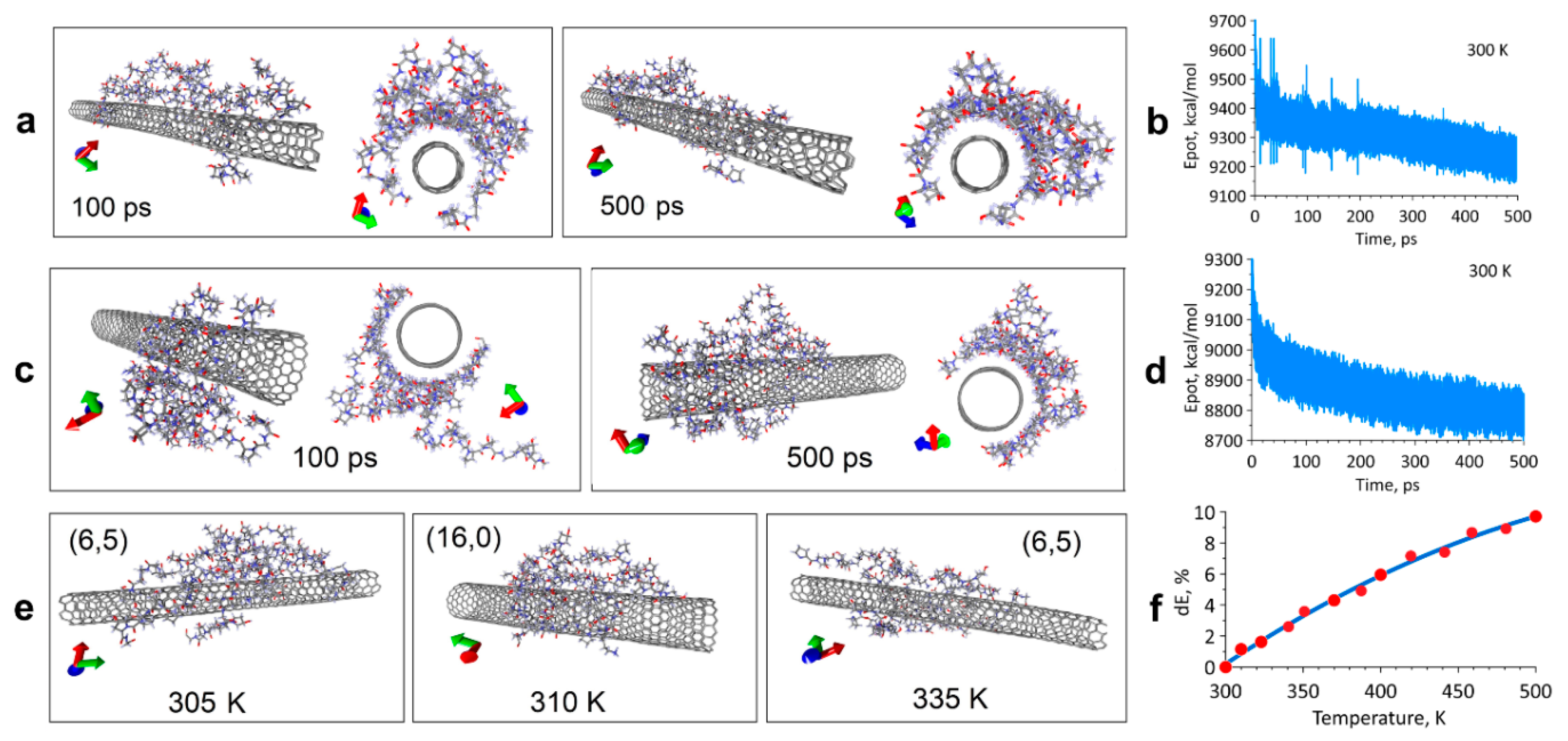
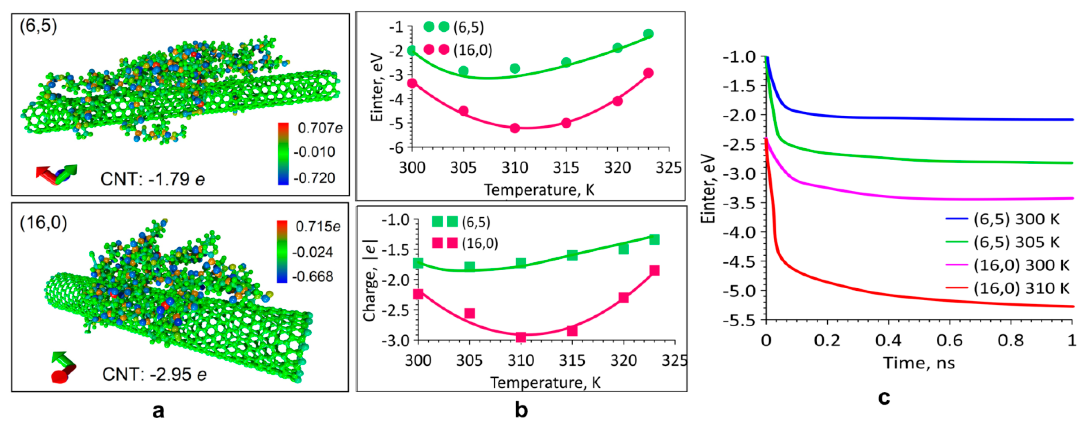
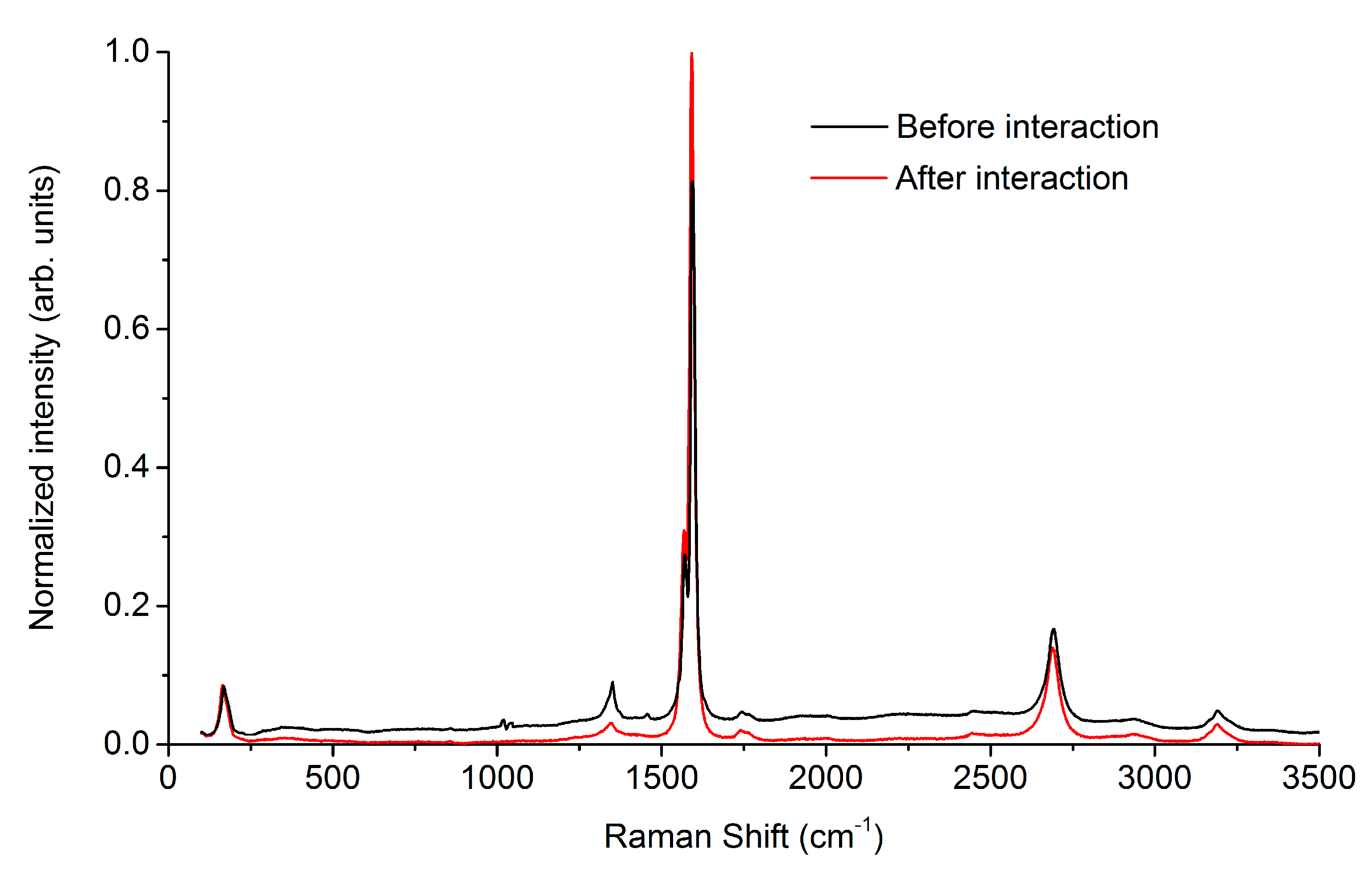
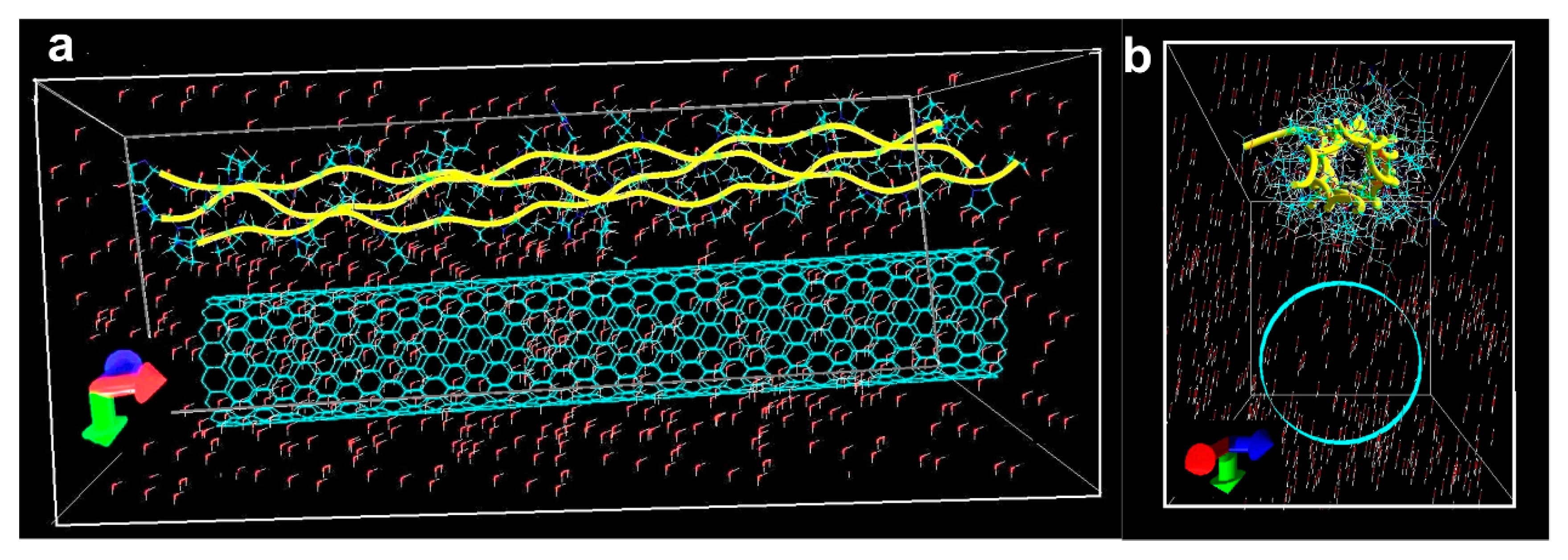
2.1. Modeling the Interaction of the SWCNT/Collagen Complex
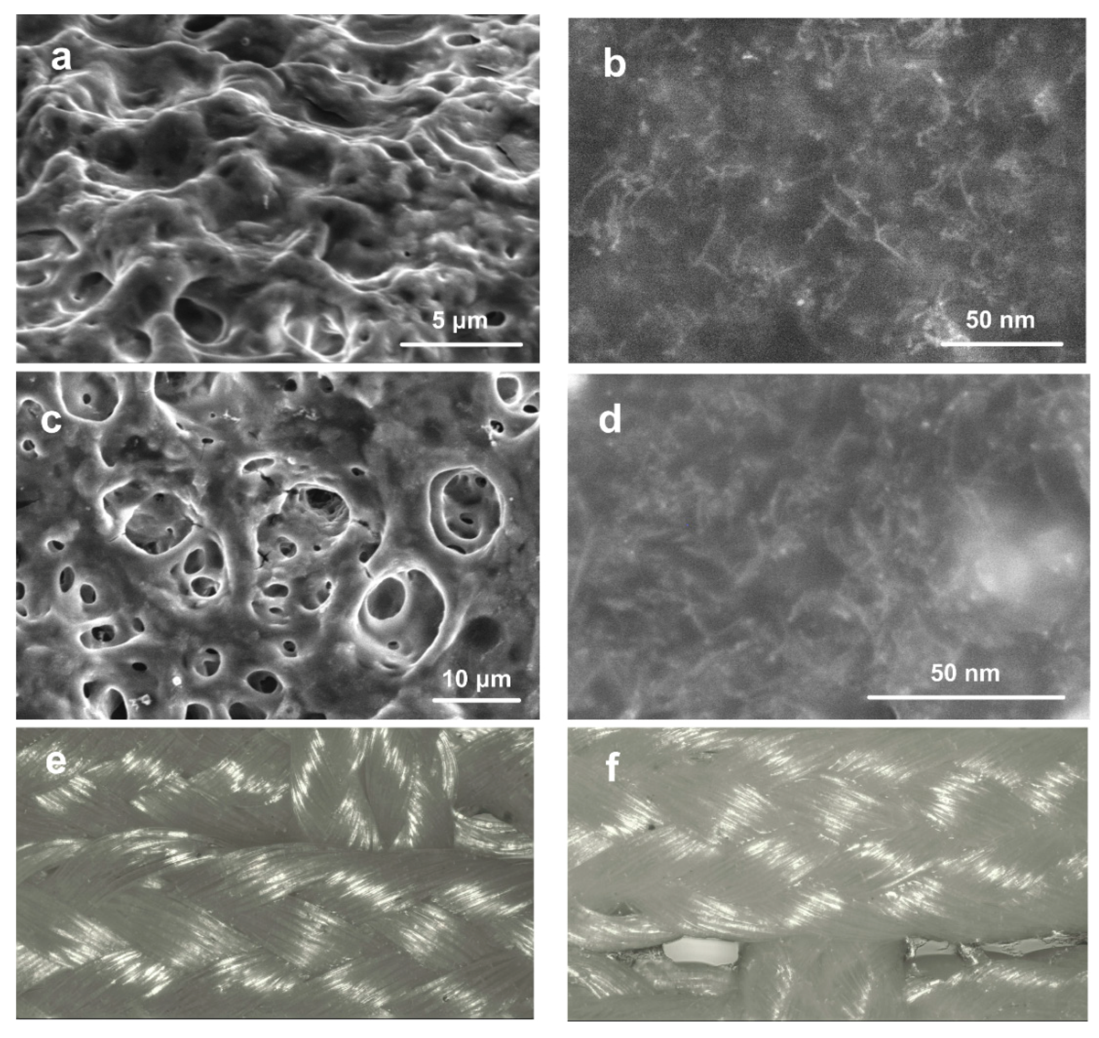
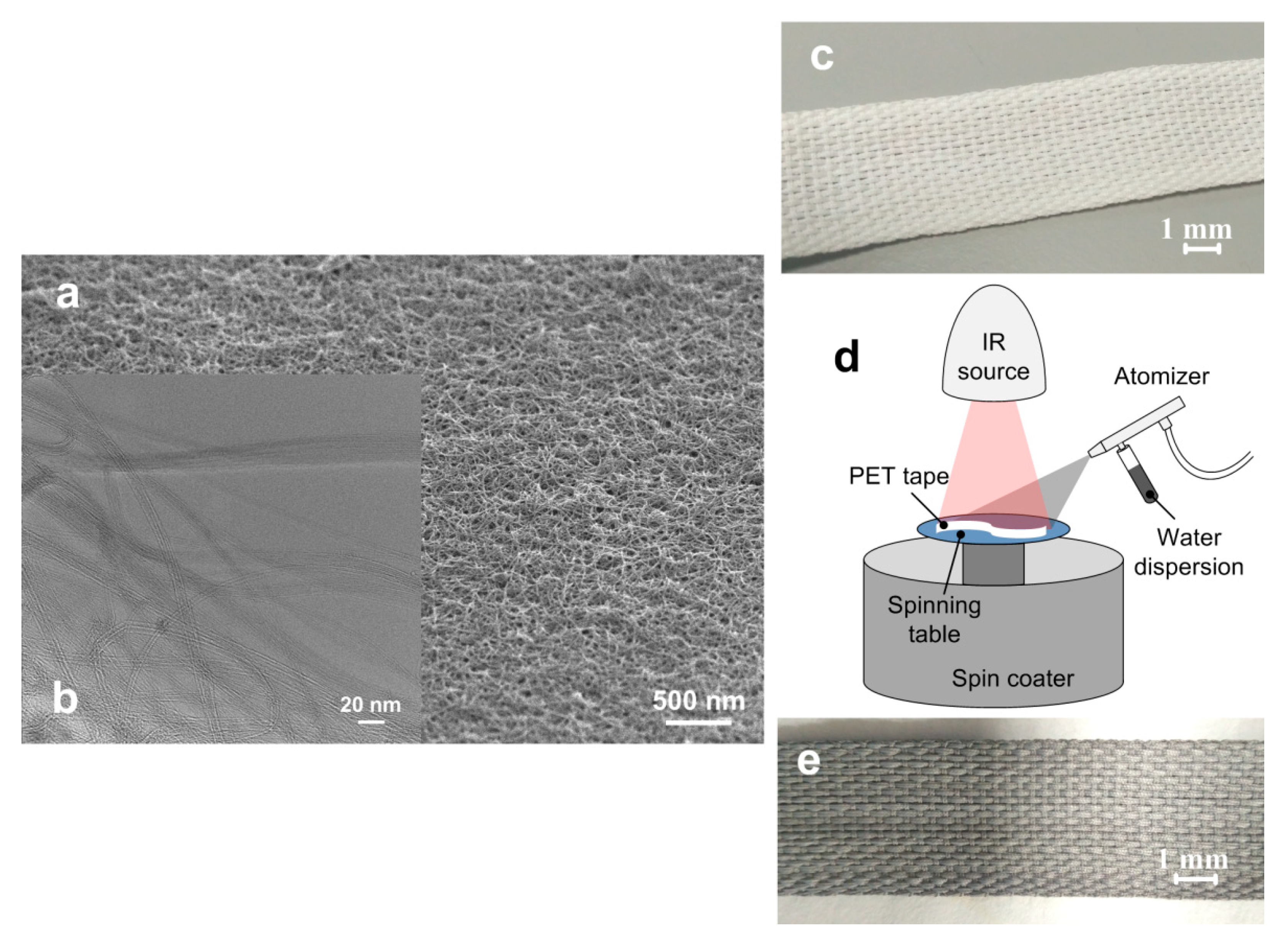
2.2. Structure of the Coating
2.3. Weight Loss
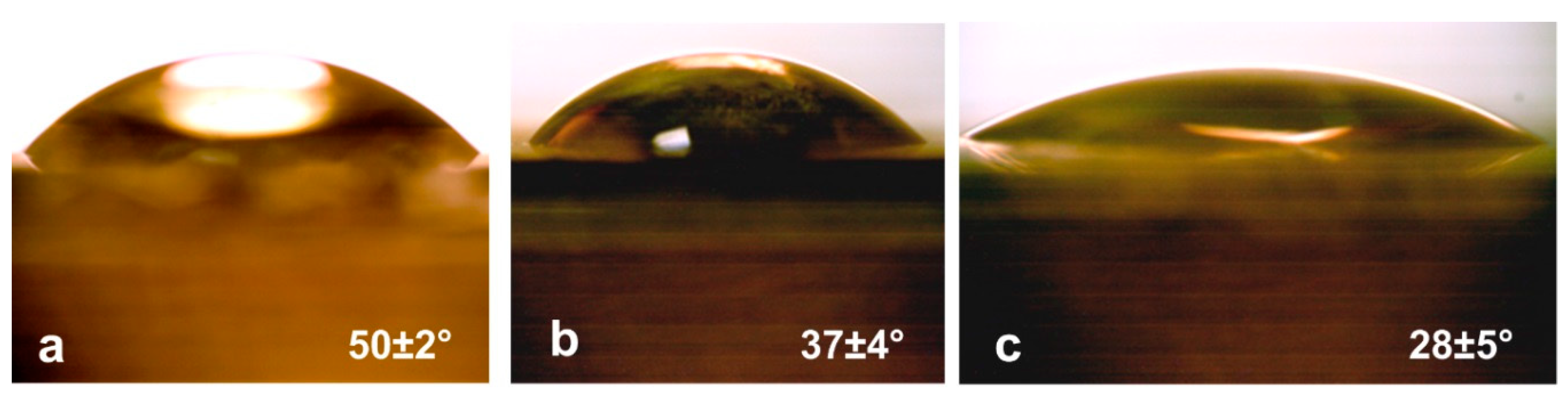
2.4. Wetting Angle
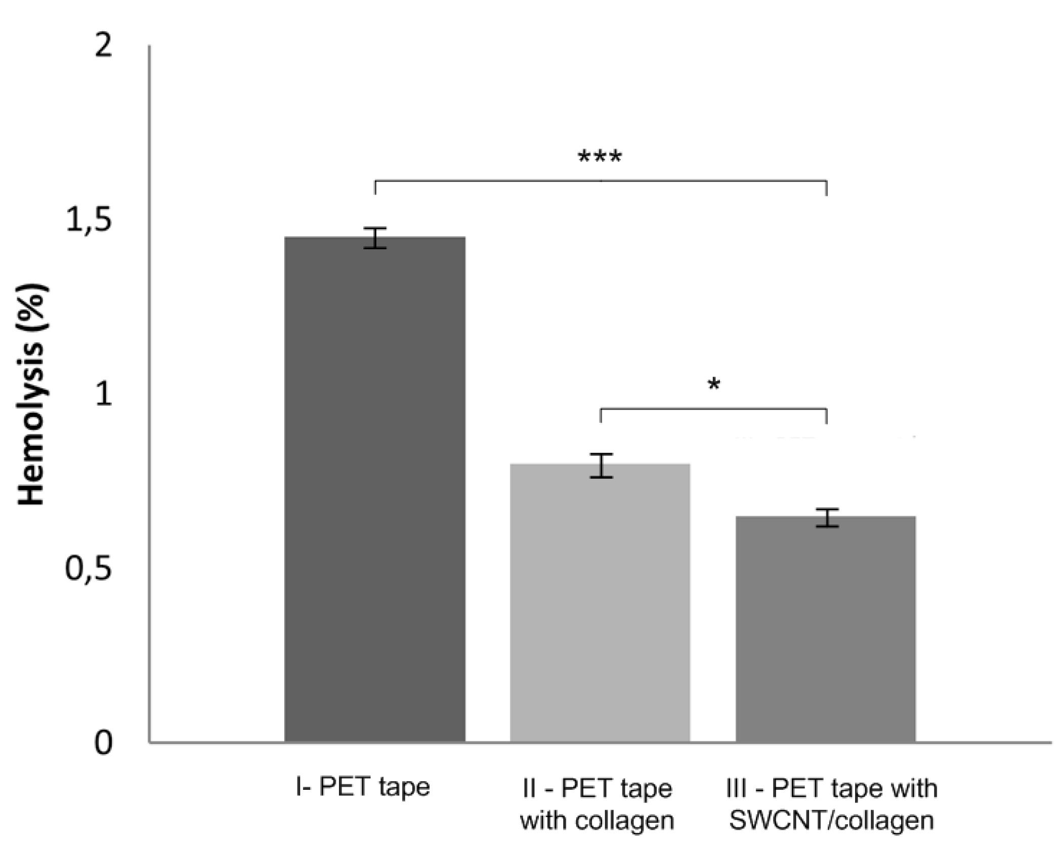
2.5. Hemolysis
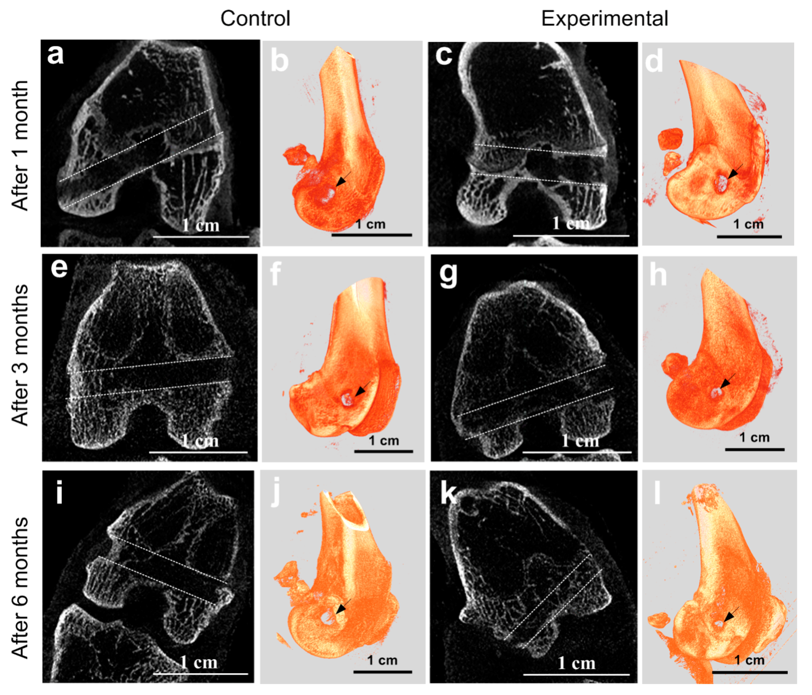
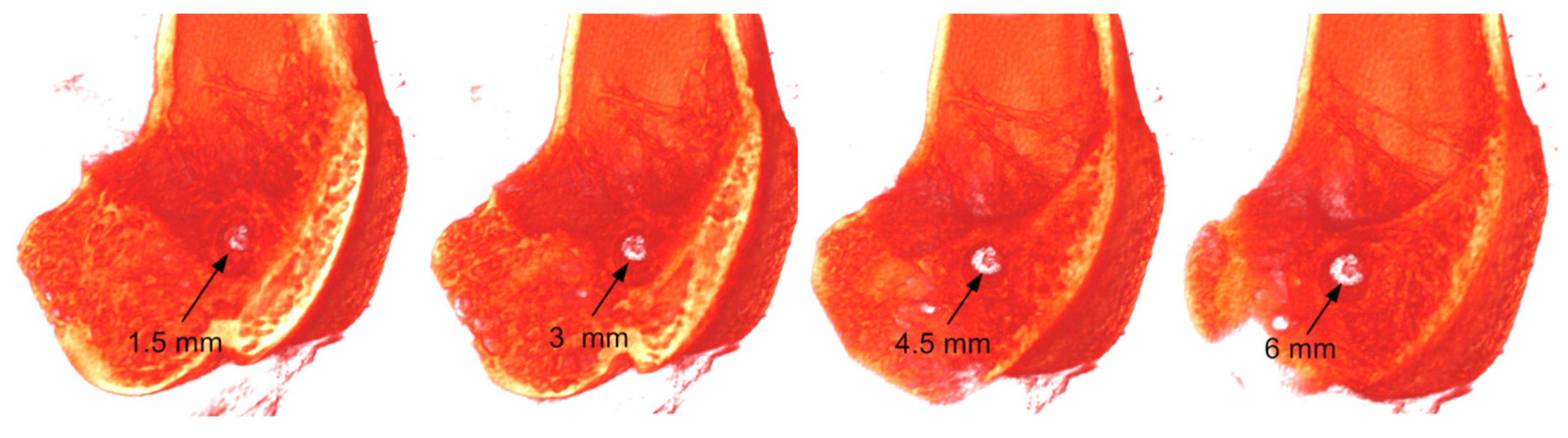
2.6. MicroCT at the Implantation Site
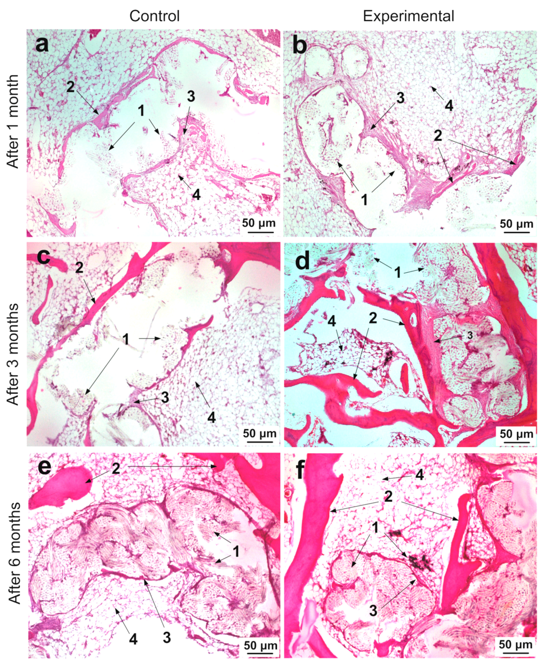
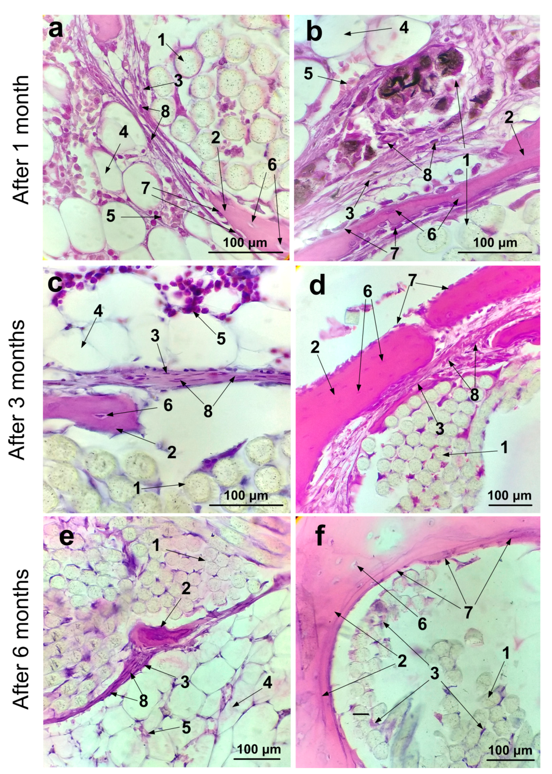
2.7. Histological Studies of Implantation Site
3. Discussion
4. Materials and Methods
4.1. Modeling the Interaction of the Complex SWCNT/Collagen
4.2. Fabrication of PET Ligament Implant with SWCNT/Collagen Coating
4.3. Persistence and Weight Loss of SWCNT/Collagen Coating for the PET Tape in Blood Serum
4.4. Wetting Angle of SWCNT/Collagen Coating
4.5. Hemolysis Assay
4.6. In vivo Experiment Procedure
4.7. MicroCT Analysis of the Implantation Site
4.8. Microstructural Analysis of the Tissue Morphology
5. Conclusions
Author Contributions
Funding
Acknowledgments
Conflicts of Interest
References
- Mao, G.; Qin, Z.; Li, Z.; Li, X.; Qiu, Y.; Bian, W. A tricalcium phosphate/polyether ether ketone anchor bionic fixation device for anterior cruciate ligament reconstruction: Safety and efficacy in a beagle model. J. Biomed. Mater. Res. B 2019, 107, 554–563. [Google Scholar] [CrossRef] [PubMed]
- Bozic, K.J.; Kurtz, S.M.; Lau, E.; Ong, K.; Chiu, V.; Vail, T.P.; Berry, D.J. The epidemiology of revision total knee arthroplasty in the United States. Clin. Orthop. Relat. Res. 2010, 468, 45–51. [Google Scholar] [CrossRef] [PubMed]
- Shormanov, A.M.; NKh, B.; RSh, S. The results of application of anterior cruciate ligament two-bundle plastics by synthetic implant in its complete tears. Saratov J. Med. Sci. Res. 2015, 11, 566–569. [Google Scholar]
- Struewer, J.; Ziring, E.; Frangen, T.M.; Efe, T.; Meißner, S.; Buecking, B.; Ishaque, B. Clinical outcome and prevalence of osteoarthritis after isolated anterior cruciate ligament reconstruction using hamstring graft: Follow-up after two and ten years. Int. Orthop. 2013, 37, 271–277. [Google Scholar] [CrossRef][Green Version]
- Roseti, L.; Buda, R.; Cavallo, C.; Desando, G.; Facchini, A.; Grigolo, B. Ligament repair: A molecular and immunohistological characterization. J. Biomed. Mater. Res. A 2008, 84, 117–127. [Google Scholar] [CrossRef]
- Murray, M.M.; Spector, M. The migration of cells from the ruptured human anterior cruciate ligament into collagen-glycosaminoglycan regeneration templates in vitro. Biomaterials 2001, 22, 2393–2402. [Google Scholar] [CrossRef]
- Wiig, M.E.; Amiel, D.; Ivarsson, M.; Nagineni, C.N.; Wallace, C.D.; Arfors, K.E. Type I procollagen gene expression in normal and early healing of the medial collateral and anterior cruciate ligaments in rabbits: An in situ hybridization study. J. Orthop. Res. 1991, 9, 374–382. [Google Scholar] [CrossRef]
- Anitua, E.; Andia, I.; Ardanza, B.; Nurden, P.; Nurden, A.T. Autologous platelets as a source of proteins for healing and tissue regeneration. Thromb. Haemost. 2004, 91, 4–15. [Google Scholar] [CrossRef]
- Cooper, R.R.; Misol, S.; Stimmel, P. Tendon and ligament insertion: A light and electron microscopic study. JBJS 1970, 52, 1–170. [Google Scholar] [CrossRef]
- Brophy, R.H.; Kovacevic, D.; Imhauser, C.W.; Stasiak, M.; Bedi, A.; Fox, A.J.; Rodeo, S.A. Effect of short-duration low-magnitude cyclic loading versus immobilization on tendon-bone healing after ACL reconstruction in a rat model. J. Bone Joint Surg. Am. 2011, 93, 381. [Google Scholar] [CrossRef]
- Gulotta, L.V.; Kovacevic, D.; Ying, L.; Ehteshami, J.R.; Montgomery, S.; Rodeo, S.A. Augmentation of tendon-to-bone healing with a magnesium-based bone adhesive. Am. J. Sports Med. 2008, 36, 1290–1297. [Google Scholar] [CrossRef]
- Wong, M.W.; Qin, L.; Tai, J.K.; Lee, S.K.; Leung, K.S.; Chan, K.M. Engineered allogeneic chondrocyte pellet for reconstruction of fibrocartilage zone at bone–tendon junction—A preliminary histological observation. J. Biomed. Mat. Res. B 2004, 70, 362–367. [Google Scholar] [CrossRef] [PubMed]
- Shah, A.A.; McCulloch, P.C.; Lowe, W.R. Failure rate of Achilles tendon allograft in primary anterior cruciate ligament reconstruction. Arthroscopy 2010, 26, 667–674. [Google Scholar] [CrossRef] [PubMed]
- Van Eck, C.F.; Schkrohowsky, J.G.; Working, Z.M.; Irrgang, J.J.; Fu, F.H. Prospective analysis of failure rate and predictors of failure after anatomic anterior cruciate ligament reconstruction with allograft. Am. J. Sports Med. 2012, 40, 800–807. [Google Scholar] [CrossRef] [PubMed]
- Tomita, F.; Yasuda, K.; Mikami, S.; Sakai, T.; Yamazaki, S.; Tohyama, H. Comparisons of intraosseous graft healing between the doubled flexor tendon graft and the bone–patellar tendon–bone graft in anterior cruciate ligament reconstruction. Arthroscopy 2001, 17, 461–476. [Google Scholar] [CrossRef]
- Pinese, C.; Gagnieu, C.; Nottelet, B.; Rondot-Couzin, C.; Hunger, S.; Coudane, J.; Garric, X. In vivo evaluation of hybrid patches composed of PLA based copolymers and collagen/chondroitin sulfate for ligament tissue regeneration. J. Biomed. Mater. Res. B 2017, 105, 1778–1788. [Google Scholar] [CrossRef]
- Nau, T.; Lavoie, P.; Duval, N. A new generation of artificial ligaments in reconstruction of the anterior cruciate ligament: Two-year follow-up of a randomised trial. J. Bone Joint Surg. Br. 2002, 84, 356–360. [Google Scholar] [CrossRef]
- Batty, L.M.; Norsworthy, C.J.; Lash, N.J.; Wasiak, J.; Richmond, A.K.; Feller, J.A. Synthetic devices for reconstructive surgery of the cruciate ligaments: A systematic review. Arthroscopy 2015, 31, 957–968. [Google Scholar] [CrossRef]
- Chen, S.; Chen, T.; Wan, F.; Jiang, J.; Feller, J.A. Synthetic Ligaments for ACL Reconstruction. In Controversies in the Technical Aspects of ACL Reconstruction; Springer: Berlin, Germany, 2017; pp. 333–341. [Google Scholar] [CrossRef]
- Li, H.; Chen, S. Biomedical coatings on polyethylene terephthalate artificial ligaments. J. Biomed. Mater. Res. A 2015, 103, 839–845. [Google Scholar] [CrossRef]
- Petersen, W.; Laprell, H. Insertion of autologous tendon grafts to the bone: A histological and immunohistochemical study of hamstring and patellar tendon grafts. Knee Surg. Sports Traumatol. Arthrosc. 2000, 8, 26–31. [Google Scholar] [CrossRef]
- Ishibashi, Y.; Toh, S.; Okamura, Y.; Sasaki, T.; Kusumi, T. Graft incorporation within the tibial bone tunnel after anterior cruciate ligament reconstruction with bone-patellar tendon-bone autograft. Am. J. Sports Med. 2001, 29, 473–479. [Google Scholar] [CrossRef] [PubMed]
- Grana, W.A.; Egle, D.M.; Mahnken, R.; Goodhart, C.W. An analysis of autograft fixation after anterior cruciate ligament reconstruction in a rabbit model. Am. J. Sports Med. 1994, 22, 344–351. [Google Scholar] [CrossRef] [PubMed]
- Nomata, H.; Nakaishi, M.; Takakuda, K. Enhanced biological fixation of ligaments to bone tissues utilizing chitin fabrics. J. Biomed. Mater. Res. B 2018, 106, 2355–2360. [Google Scholar] [CrossRef] [PubMed]
- Liu, Y.; Rath, B.; Tingart, M.; Eschweiler, J. Role of implants surface modification in osseointegration: A systematic review. J. Biomed. Mater. Res. A 2020, 108, 470–484. [Google Scholar] [CrossRef] [PubMed]
- Jiang, J.; Wan, F.; Yang, J.; Hao, W.; Wang, Y.; Yao, J.; Chen, S. Enhancement of osseointegration of polyethylene terephthalate artificial ligament by coating of silk fibroin and depositing of hydroxyapatite. Int. J. Nanomed. 2014, 9, 4569. [Google Scholar] [CrossRef]
- Yang, J.; Jiang, J.; Li, Y.; Li, H.; Jing, Y.; Wu, P.; Chen, S. A new strategy to enhance artificial ligament graft osseointegration in the bone tunnel using hydroxypropylcellulose. Int. Orthop. 2013, 37, 515–521. [Google Scholar] [CrossRef]
- Brasinika, D.; Tsigkou, O.; Tsetsekou, A.; Missirlis, Y.F. Bioinspired synthesis of hydroxyapatite nanocrystals in the presence of collagen and l-arginine: Candidates for bone regeneration. J. Biomed. Mater. Res. B 2016, 104, 458–469. [Google Scholar] [CrossRef]
- Rajesh, P.; Muraleedharan, C.V.; Sureshbabu, S.; Komath, M.; Varma, H. Preparation and analysis of chemically gradient functional bioceramic coating formed by pulsed laser deposition. J. Mater. Sci. Mater. Med. 2012, 23, 339–348. [Google Scholar] [CrossRef]
- He, P.; Sahoo, S.; Ng, K.S.; Chen, K.; Toh, S.L.; Goh, J.C.H. Enhanced osteoinductivity and osteoconductivity through hydroxyapatite coating of silk-based tissue-engineered ligament scaffold. J. Biomed. Mater. Res. A 2013, 101, 555–566. [Google Scholar] [CrossRef]
- Li, H.; Ge, Y.; Wu, Y.; Jiang, J.; Gao, K.; Zhang, P.; Chen, S. Hydroxyapatite coating enhances polyethylene terephthalate artificial ligament graft osseointegration in the bone tunnel. Int. Orthop. 2011, 35, 1561–1567. [Google Scholar] [CrossRef]
- Leach, J.K.; Kaigler, D.; Wang, Z.; Krebsbach, P.H.; Mooney, D.J. Coating of VEGF-releasing scaffolds with bioactive glass for angiogenesis and bone regeneration. Biomaterials 2006, 27, 3249–3255. [Google Scholar] [CrossRef] [PubMed]
- Andrade, Â.L.; Valério, P.; de Goes, A.M.; de Fátima Leite, M.; Domingues, R.Z. Influence of recovering collagen with bioactive glass on osteoblast behavior. J. Biomed. Mater. Res. B 2007, 83, 481–489. [Google Scholar] [CrossRef]
- Wu, Y.; Chen, S.; Jiang, J.; Li, H.; Gao, K.; Zhang, P. The effect of 58S bioactive glass coating on polyethylene terephthalates in graft-bone healing. J. Bionic Eng. 2012, 9, 470–477. [Google Scholar] [CrossRef]
- Xie, X.H.; Yu, X.W.; Zeng, S.X.; Du, R.L.; Hu, Y.H.; Yuan, Z.; Tang, T.T. Enhanced osteointegration of orthopaedic implant gradient coating composed of bioactive glass and nanohydroxyapatite. J. Mater. Sci. Mater. Med. 2010, 21, 2165–2173. [Google Scholar] [CrossRef] [PubMed]
- Valenzuela, F.; Covarrubias, C.; Martínez, C.; Smith, P.; Díaz-Dosque, M.; Yazdani-Pedram, M. Preparation and bioactive properties of novel bone-repair bionanocomposites based on hydroxyapatite and bioactive glass nanoparticles. J. Biomed. Mater. Res. B 2012, 100, 1672–1682. [Google Scholar] [CrossRef]
- Cholewa-Kowalska, K.; Kokoszka, J.; Laczka, M.; Niedzwiedzki, L.; Madej, W.; Osyczka, A.M. Gel-derived bioglass as a compound of hydroxyapatite composites. Biomed. Mater. 2009, 4, 055007. [Google Scholar] [CrossRef]
- Tan, F.; Naciri, M.; Al-Rubeai, M. Osteoconductivity and growth factor production by MG63 osteoblastic cells on bioglass-coated orthopedic implants. Biotechnol. Bioeng. 2011, 108, 454–464. [Google Scholar] [CrossRef]
- Zhao, N.; Wang, X.; Qin, L.; Zhai, M.; Yuan, J.; Chen, J.; Li, D. Effect of hyaluronic acid in bone formation and its applications in dentistry. J. Biomed. Mater. Res. A 2016, 104, 1560–1569. [Google Scholar] [CrossRef]
- Li, H.; Ge, Y.; Zhang, P.; Wu, L.; Chen, S. The effect of layer-by-layer chitosan-hyaluronic acid coating on graft-to-bone healing of a poly(ethylene terephthalate) artificial ligament. J. Biomater. Sci. Polym. Ed. 2012, 23, 425–438. [Google Scholar] [CrossRef]
- Li, H.; Chen, C.; Zhang, S.; Jiang, J.; Tao, H.; Xu, J.; Chen, S. The use of layer by layer self-assembled coatings of hyaluronic acid and cationized gelatin to improve the biocompatibility of poly(ethylene terephthalate) artificial ligaments for reconstruction of the anterior cruciate ligament. Acta Biomater. 2012, 8, 4007–4019. [Google Scholar] [CrossRef] [PubMed]
- Cho, S.; Li, H.; Chen, C.; Jiang, J.; Tao, H.; Chen, S. Cationised gelatin and hyaluronic acid coating enhances polyethylene terephthalate artificial ligament graft osseointegration in porcine bone tunnels. Int. Orthop. 2013, 37, 507–513. [Google Scholar] [CrossRef][Green Version]
- Wetteland, C.L.; Liu, H. Optical and biological properties of polymer-based nanocomposites with improved dispersion of ceramic nanoparticles. J. Biomed. Mater. Res. A 2018, 106, 2692–2707. [Google Scholar] [CrossRef] [PubMed]
- Li, X.; Yang, Y.; Fan, Y.; Feng, Q.; Cui, F.Z.; Watari, F. Biocomposites reinforced by fibers or tubes as scaffolds for tissue engineering or regenerative medicine. J. Biomed. Mater. Res. A 2014, 102, 1580–1594. [Google Scholar] [CrossRef] [PubMed]
- MacDonald, R.A.; Laurenzi, B.F.; Viswanathan, G.; Ajayan, P.M.; Stegemann, J.P. Collagen–carbon nanotube composite materials as scaffolds in tissue engineering. J. Biomed. Mater. Res. A 2005, 74, 489–496. [Google Scholar] [CrossRef]
- Correia Pinto, V.; Costa-Almeida, R.; Rodrigues, I.; Guardão, L.; Soares, R.; Miranda Guedes, R. Exploring the in vitro and in vivo compatibility of PLA, PLA/GNP and PLA/CNT-COOH biodegradable nanocomposites: Prospects for tendon and ligament applications. J. Biomed. Mater. Res. A 2017, 105, 2182–2190. [Google Scholar] [CrossRef] [PubMed]
- Patel, S.C.; Alam, O.; Sitharaman, B. Osteogenic differentiation of human adipose derived stem cells on chemically crosslinked carbon nanomaterial coatings. J. Biomed. Mater. Res. A 2018, 106, 1189–1199. [Google Scholar] [CrossRef] [PubMed]
- Gerasimenko, A.; Zhurbina, N.; Kurilova, U.; Polokhin, A.; Ryabkin, D.; Savelyev, M.; Garcia-Ramirez, M.A. The technology of laser fabrication of cell 3D scaffolds based on proteins and carbon nanoparticles. 3D Print. Opt. Addit. Photonic Manuf. 2018, 10675, 1067510. [Google Scholar] [CrossRef]
- Gerasimenko, A.Y.; Ichkitidze, L.P.; Podgaetsky, V.M.; Savelyev, M.S.; Selishchev, S.V. Laser nanostructuring 3-D bioconstruction based on carbon nanotubes in a water matrix of albumin. Biophotonics Photonic Solut. Better Health Care V 2016, 9887, 988725-1–988725-10. [Google Scholar] [CrossRef]
- Gerasimenko, A.Y.; Kitsyuk, E.P.; Kuksin, A.V.; Ryazanov, R.M.; Savitskiy, A.I.; Savelyev, M.S.; Pavlov, A.A. Influence of laser structuring and barium nitrate treatment on morphology and electrophysical characteristics of vertically aligned carbon nanotube arrays. Diam. Relat. Mater. 2019, 96, 104–111. [Google Scholar] [CrossRef]
- Gerasimenko, A.Y.; Ten, G.N.; Ryabkin, D.I.; Shcherbakova, N.E.; Morozova, E.A.; Ichkitidze, L.P. The study of the interaction mechanism between bovine serum albumin and single-walled carbon nanotubes depending on their diameter and concentration in solid nanocomposites by vibrational spectroscopy. Spectrochim. Acta A 2020, 227, 117682. [Google Scholar] [CrossRef] [PubMed]
- Vardharajula, S.; Ali, S.Z.; Tiwari, P.M.; Eroğlu, E.; Vig, K.; Dennis, V.A.; Singh, S.R. Functionalized carbon nanotubes: Biomedical applications. Int. J. Nanomed. 2012, 7, 5361. [Google Scholar] [CrossRef]
- Slepchenkov, M.M.; Gerasimenko, A.Y.; Telyshev, D.V.; Glukhova, O.E. Protein-Polymer Matrices with Embedded Carbon Nanotubes for Tissue Engineering: Regularities of Formation and Features of Interaction with Cell Membranes. Materials 2019, 12, 3083. [Google Scholar] [CrossRef]
- Gerasimenko, A.Y.; Glukhova, O.E.; Savostyanov, G.V.; Podgaetsky, V.M. Laser structuring of carbon nanotubes in the albumin matrix for the creation of composite biostructures. J. Biomed. Opt. 2017, 22, 065003. [Google Scholar] [CrossRef] [PubMed]
- Cui, H.F.; Vashist, S.K.; Al-Rubeaan, K.; Luong, J.H.; Sheu, F.S. Interfacing carbon nanotubes with living mammalian cells and cytotoxicity issues. Chem. Res. Toxicol. 2010, 23, 1131–1147. [Google Scholar] [CrossRef] [PubMed]
- Pinto, V.C.; Ramos, T.; Alves, A.S.F.; Xavier, J.; Tavares, P.J.; Moreira, P.M.G.P.; Guedes, R.M. Dispersion and failure analysis of PLA, PLA/GNP and PLA/CNT-COOH biodegradable nanocomposites by SEM and DIC inspection. Eng. Fail. Anal. 2017, 71, 63–71. [Google Scholar] [CrossRef]
- Patel, S.C.; Lalwani, G.; Grover, K.; Qin, Y.X.; Sitharaman, B. Fabrication and cytocompatibility of in situ crosslinked carbon nanomaterial films. Sci. Rep. 2015, 5, 10261. [Google Scholar] [CrossRef]
- Fonseca-García, A.; Mota-Morales, J.D.; Quintero-Ortega, I.A.; García-Carvajal, Z.Y.; Martínez-López, V.; Ruvalcaba, E.; Terrones, M. Effect of doping in carbon nanotubes on the viability of biomimetic chitosan-carbon nanotubes-hydroxyapatite scaffolds. J. Biomed. Mater. Res. A 2014, 102, 3341–3351. [Google Scholar] [CrossRef]
- Abarrategi, A.; Gutierrez, M.C.; Moreno-Vicente, C.; Hortigüela, M.J.; Ramos, V.; Lopez-Lacomba, J.L.; del Monte, F. Multiwall carbon nanotube scaffolds for tissue engineering purposes. Biomaterials 2008, 29, 94–102. [Google Scholar] [CrossRef]
- Tanaka, M.; Aoki, K.; Haniu, H.; Kamanaka, T.; Takizawa, T.; Sobajima, A.; Saito, N. Applications of Carbon Nanotubes in Bone Regenerative Medicine. J. Nanomater. 2020, 10, 659. [Google Scholar] [CrossRef]
- Hirata, E.; Uo, M.; Nodasaka, Y.; Takita, H.; Ushijima, N.; Akasaka, T.; Yokoyama, A. 3D collagen scaffolds coated with multiwalled carbon nanotubes: Initial cell attachment to internal surface. J. Biomed. Mater. Res. B 2010, 93, 544–550. [Google Scholar] [CrossRef]
- Lavoie, P.; Fletcher, J.; Duval, N. Patient satisfaction needs as related to knee stability and objective findings after ACL reconstruction using the LARS artificial ligament. Knee 2000, 7, 157–163. [Google Scholar] [CrossRef]
- Gao, K.; Chen, S.; Wang, L.; Zhang, W.; Kang, Y.; Dong, Q.; Li, L. Anterior cruciate ligament reconstruction with LARS artificial ligament: A multicenter study with 3-to 5-year follow-up. Arthroscopy 2010, 26, 515–523. [Google Scholar] [CrossRef] [PubMed]
- Guidoin, M.F.; Marois, Y.; Bejui, J.; Poddevin, N.; King, M.W.; Guidoin, R. Analysis of retrieved polymer fiber based replacements for the ACL. Biomaterials 2000, 21, 2461–2474. [Google Scholar] [CrossRef]
- Da Silva, E.E.; Della Colleta, H.H.; Ferlauto, A.S.; Moreira, R.L.; Resende, R.R.; Oliveira, S.; Ladeira, L.O. Nanostructured 3-D collagen/nanotube biocomposites for future bone regeneration scaffolds. Nano Res. 2009, 2, 462–473. [Google Scholar] [CrossRef]
- Huang, C.Y.; Mow, V.C.; Ateshian, G.A. The role of flow-independent viscoelasticity in the biphasic tensile and compressive responses of articular cartilage. J. Biomech. Eng. 2001, 123, 410–417. [Google Scholar] [CrossRef]
- Fyhrie, D.P.; Barone, J.R. Polymer dynamics as a mechanistic model for the flow-independent viscoelasticity of cartilage. J. Biomech. Eng. 2003, 125, 578–584. [Google Scholar] [CrossRef] [PubMed]
- Ramachandran, B.; Chakraborty, S.; Kannan, R.; Dixit, M.; Muthuvijayan, V. Immobilization of hyaluronic acid from Lactococcus lactis on polyethylene terephthalate for improved biocompatibility and drug release. Carbohydr. Polym. 2019, 206, 132–140. [Google Scholar] [CrossRef] [PubMed]
- Suvarna, S.K.; Layton, C.J.; Bancroft, J.D. Tissue processing. In Bancroft’s Theory and Practice of Histological Techniques, 7th ed.; Churchill Livingstone Elsevier: Oxford, UK, 2013; pp. 73–83a. [Google Scholar]
- Kim, H.M.; Galatz, L.M.; Das, R.; Havlioglu, N.; Rothermich, S.Y.; Thomopoulos, S. The role of transforming growth factor beta isoforms in tendon-to-bone healing. Connect. Tissue Res. 2011, 52, 87–98. [Google Scholar] [CrossRef]
- Manning, C.N.; Kim, H.M.; Sakiyama-Elbert, S.; Galatz, L.M.; Havlioglu, N.; Thomopoulos, S. Sustained delivery of transforming growth factor beta three enhances tendon-to-bone healing in a rat model. J. Orthop. Res. 2011, 29, 1099–1105. [Google Scholar] [CrossRef]
- Wang, C.K.; Ho, M.L.; Wang, G.J.; Chang, J.K.; Chen, C.H.; Fu, Y.C.; Fu, H.H. Controlled-release of rhBMP-2 carriers in the regeneration of osteonecrotic bone. Biomaterials 2009, 30, 4178–4186. [Google Scholar] [CrossRef]
- Benglis, D.; Wang, M.Y.; Levi, A.D. A comprehensive review of the safety profile of bone morphogenetic protein in spine surgery. Oper. Neurosurg. 2008, 62, ONS423–ONS431. [Google Scholar] [CrossRef]
- Zhao, B.; Hu, H.; Mandal, S.K.; Haddon, R.C. A bone mimic based on the self-assembly of hydroxyapatite on chemically functionalized single-walled carbon nanotubes. Chem. Mater. 2005, 17, 3235–3241. [Google Scholar] [CrossRef]
- Usui, Y.; Aoki, K.; Narita, N.; Murakami, N.; Nakamura, I.; Nakamura, K.; Ishigaki, N.; Yamazaki, H.; Horiuchi, H.; Kato, H.; et al. Carbon nanotubes with high bone-tissue compatibility and bone-formation acceleration effects. Small 2008, 4, 240–246. [Google Scholar] [CrossRef] [PubMed]
- Hirata, E.; Uo, M.; Takita, H.; Akasaka, T.; Watari, F.; Yokoyama, A. Multiwalled carbon nanotube-coating of 3D collagen scaffolds for bone tissue engineering. Carbon 2011, 49, 3284–3291. [Google Scholar] [CrossRef]
- Aoki, N.; Akasaka, T.; Watari, F.; Yokoyama, A. Carbon nanotubes as scaffolds for cell culture and effect on cellular functions. Dent. Mater. J. 2007, 26, 178–185. [Google Scholar] [CrossRef] [PubMed]
- Narita, N.; Kobayashi, Y.; Nakamura, H.; Maeda, K.; Ishihara, A.; Mizoguchi, T. Multiwalled carbon nanotubes specifically inhibit osteoclast differentiation and function. Nano Lett. 2009, 9, 1406–1413. [Google Scholar] [CrossRef] [PubMed]
- Banerjee, S.; Hemraj-Benny, T.; Wong, S.S. Covalent surface chemistry of single-walled carbon nanotubes. Adv. Mater. 2005, 17, 17–29. [Google Scholar] [CrossRef]
- Pastorin, G.; Wu, W.; Wieckowski, S.; Briand, J.P.; Kostarelos, K.; Prato, M.; Bianco, A. Double functionalisation of carbon nanotubes for multimodal drug delivery. Chem. Commun. 2006, 1182–1184. [Google Scholar] [CrossRef]
- Myllyharju, J.; Kivirikko, K.I. Collagens, modifying enzymes and their mutations in humans, flies and worms. Trends Genet. 2004, 20, 33–43. [Google Scholar] [CrossRef]
- Gerasimenko, A.Y.; Zhurbina, N.N.; Kurilova, U.E.; Ichkitidze, L.P.; Selishchev, S.V.; Suetina, I.A.; Mezentseva, M.A.; Russu, L.I.; Zar, V.V.; Podgaetskii, V.M. Knee joint ligament implants with composite nanocoatings. Biomed. Eng. 2016, 50, 206–209. [Google Scholar] [CrossRef]
- Ageeva, S.A.; Eliseenko, V.I.; Gerasimenko, A.Y.; Ichkitidze, L.P.; Podgaetsky, V.M.; Selishchev, S.V. Possible medical application of laser nanoengineering. Biomed. Eng. 2011, 44, 233. [Google Scholar] [CrossRef]
- Zhurbina, N.N.; Ignatov, D.A.; Kurilova, U.E.; Ryabkin, D.I.; Svetlichnyi, V.A.; Gerasimenko, A.Y. Structure and Biochemical Study of Nanocomposite Bioconstruction for Restoration of Bone-cartilaginous Defects. KnE Energy 2018, 541–546. [Google Scholar] [CrossRef]
- Gerasimenko, A.; Kurilova, U.; Zhurbina, N.; Ignatov, D.; Fedorova, J.; Privalova, P.; Polokhin, A.; Ryabkin, D.; Savelyev, M.; Ichkitidze, L.; et al. Laser nanocomposites based on proteins and carbon nanotubes for restoration of biological tissues. International Conference on Atomic and Molecular Pulsed Lasers XIII. Int. Soc. Opt. Photonics 2018, 10614, 106140H-1–106140H-6. [Google Scholar] [CrossRef]
- Li, M.; Liu, X.; Zhao, X.; Yang, F.; Wang, X.; Li, Y. Metallic catalysts for structure-controlled growth of single-walled carbon nanotubes. Top. Curr. Chem. 2017, 375, 29. [Google Scholar] [CrossRef] [PubMed]
- The Amber Project. Available online: http://ambermd:AmberModels.php (accessed on 8 December 2019).
- Elstner, M.; Porezag, D.; Jungnickel, G.; Elsner, J.; Haugk, M.; Frauenheim, T. Self-Consistent-Charge Density-Functional Tight-Binding Method for Simulations of Complex Materials Properties. Phys. Rev. B 1998, 58, 7260–7268. [Google Scholar] [CrossRef]
- Bagrov, S.; Leontieva, G.; Novikov, S.; Maklakova, I. Biocompatible Optically Transparent Polymeric Material. U.S. Patent Application No. 20030018123A1, 23 January 2003. [Google Scholar]
- Fedorov, S.N.; Bagrov, S.N.; Maklakova, I.A.; Novikov, S.V.; Shelukhina, G.D. Biocompatible Polymeric Materials, Methods of Preparing Such Materials and Uses Thereof. U.S. Patent No. 5993796A, 30 November 1999. [Google Scholar]
- Savelyev, M.S.; Agafonova, N.O.; Vasilevsky, P.N.; Ryabkin, D.I.; Telyshev, D.V.; Timashev, P.S.; Gerasimenko, A.Y. Effects of pulsed and continuous-wave laser radiation on the fabrication of tissue-engineered composite structures. Opt. Eng. 2020, 59, 061623. [Google Scholar] [CrossRef]
- Savelyev, M.S.; Gerasimenko, A.Y.; Vasilevsky, P.N.; Fedorova, Y.O.; Groth, T.; Ten, G.N.; Telyshev, D.V. Spectral analysis combined with nonlinear optical measurement of laser printed biopolymer composites comprising chitosan/SWCNT. Anal. Biochem. 2020, 113710. [Google Scholar] [CrossRef] [PubMed]
- Wiegand, C.; Abel, M.; Ruth, P.; Wilhelms, T.; Schulze, D.; Norgauer, J.; Hipler, U.C. Effect of the sterilization method on the performance of collagen type I on chronic wound parameters in vitro. J. Biomed. Mater. Res. B 2009, 90, 710–719. [Google Scholar] [CrossRef]
- Silva, G.G.; da Costa Valente, M.L.; Bachmann, L.; Dos Reis, A.C. Use of polyethylene terephthalate as a prosthetic component in the prosthesis on an overdenture implant. Mater. Sci. Eng. C 2019, 99, 1341–1349. [Google Scholar] [CrossRef]
- Morresi, A.L.; D’Amario, M.; Capogreco, M.; Gatto, R.; Marzo, G.; D’Arcangelo, C.; Monaco, A. Thermal cycling for restorative materials: Does a standardized protocol exist in laboratory testing? A literature review. J. Mech. Behav. Biomed. 2014, 29, 295–308. [Google Scholar] [CrossRef]
- Gale, M.S.; Darvell, B.W. Thermal cycling procedures for laboratory testing of dental restorations. J. Dent. 1999, 27, 89–99. [Google Scholar] [CrossRef]
- Tong, X.; Shi, Z.; Xu, L.; Lin, J.; Zhang, D.; Wang, K.; Wen, C. Degradation behavior, cytotoxicity, hemolysis, and antibacterial properties of electro-deposited Zn–Cu metal foams as potential biodegradable bone implants. Acta Biomater. 2020, 102, 481–492. [Google Scholar] [CrossRef] [PubMed]
- Bancroft, J.D.; Cook, H.C. Manual of Histological Techniques, 1st ed.; Churchill Livingstone: New York, NY, USA, 1984. [Google Scholar] [CrossRef]


© 2020 by the authors. Licensee MDPI, Basel, Switzerland. This article is an open access article distributed under the terms and conditions of the Creative Commons Attribution (CC BY) license (http://creativecommons.org/licenses/by/4.0/).
Share and Cite
Gerasimenko, A.Y.; Zhurbina, N.N.; Cherepanova, N.G.; Semak, A.E.; Zar, V.V.; Fedorova, Y.O.; Eganova, E.M.; Pavlov, A.A.; Telyshev, D.V.; Selishchev, S.V.; et al. Frame Coating of Single-Walled Carbon Nanotubes in Collagen on PET Fibers for Artificial Joint Ligaments. Int. J. Mol. Sci. 2020, 21, 6163. https://doi.org/10.3390/ijms21176163
Gerasimenko AY, Zhurbina NN, Cherepanova NG, Semak AE, Zar VV, Fedorova YO, Eganova EM, Pavlov AA, Telyshev DV, Selishchev SV, et al. Frame Coating of Single-Walled Carbon Nanotubes in Collagen on PET Fibers for Artificial Joint Ligaments. International Journal of Molecular Sciences. 2020; 21(17):6163. https://doi.org/10.3390/ijms21176163
Chicago/Turabian StyleGerasimenko, Alexander Yu., Natalia N. Zhurbina, Nadezhda G. Cherepanova, Anna E. Semak, Vadim V. Zar, Yulia O. Fedorova, Elena M. Eganova, Alexander A. Pavlov, Dmitry V. Telyshev, Sergey V. Selishchev, and et al. 2020. "Frame Coating of Single-Walled Carbon Nanotubes in Collagen on PET Fibers for Artificial Joint Ligaments" International Journal of Molecular Sciences 21, no. 17: 6163. https://doi.org/10.3390/ijms21176163
APA StyleGerasimenko, A. Y., Zhurbina, N. N., Cherepanova, N. G., Semak, A. E., Zar, V. V., Fedorova, Y. O., Eganova, E. M., Pavlov, A. A., Telyshev, D. V., Selishchev, S. V., & Glukhova, O. E. (2020). Frame Coating of Single-Walled Carbon Nanotubes in Collagen on PET Fibers for Artificial Joint Ligaments. International Journal of Molecular Sciences, 21(17), 6163. https://doi.org/10.3390/ijms21176163