
Ni-Doped Pr0.5Ba0.5CoO3+δ Perovskite with Low Polarization Resistance and Thermal Expansivity as a Cathode Material for Solid Oxide Fuel Cells

 , ,
, ,
Abstract
1. Introduction
2. Results and Discussion
3. Preparation and Characterization
3.1. Experimental Preparation
3.2. Characterization
3.3. Electrochemical Test
4. Conclusions
Supplementary Materials
Author Contributions
Funding
Institutional Review Board Statement
Informed Consent Statement
Data Availability Statement
Acknowledgments
Conflicts of Interest
References
- Teng, Y.K.; Li, J.X.; Wang, P.C.; Yang, Y.F.; Zhai, Y.J.; Jin, F.J. Properties of Nickel Doped Praseodymium Ferrate as a Symmetrical Solid Oxide Fuel Cell Electrode. J. Chin. Ceram. Soc. 2023, 51, 1007–1014. [Google Scholar]
- Ahmad, M.Z.; Ahmad, S.H.; Chen, R.S.; Ismail, A.F.; Hazan, R.; Baharuddin, N.A. Review on recent advancement in cathode material for lower and intermediate temperature solid oxide fuel cells application. Int. J. Hydrogen Energy 2022, 47, 1103–1120. [Google Scholar]
- Dong, Y.L.; Li, Z.B.; Wang, A.; Hua, S.Y. Oxygen reduction performance of F-doped La1-xSrxCo1-yFeyO3-δ solid oxide fuel cells cathode. Chin. J. Eng. 2022, 44, 1014–1019. [Google Scholar]
- Woo, S.H.; Baek, S.Y.; Kim, Y.S. Investigation of the properties of layered perovskite materials with varying constituent elements as SOFC cathodes. Mater. Lett. 2024, 370, 136868. [Google Scholar]
- Zhang, Y.J.; Zhou, D.F.; Zhu, X.F.; Wang, N.; Bai, J.H.; Hu, L.; Gong, H.F.; Zhao, B.Y.; Yan, W.F. Preparation of Pr, Co co-doped BaFeO3–δ-based nanofiber cathode materials by electrospinning. Int. J. Hydrogen Energy 2024, 50, 992–1003. [Google Scholar] [CrossRef]
- He, F.; Zhu, F.; Liu, D.L.; Zhou, Y.C.; Sasaki, K.; Choi, Y.W.; Liu, M.L.; Chen, Y. A reversible perovskite air electrode for active and durable oxygen reduction and evolution reactions via the A-site entropy engineering. Mater. Today Chem 2023, 63, 89–98. [Google Scholar]
- Gu, H.X.; Yang, G.M.; Hu, Y.; Liang, M.Z.; Chen, S.H.; Ran, R.; Xu, M.G.; Wang, W.; Zhou, W.; Shao, Z.P. Enhancing the oxygen reduction activity of PrBaCo2O5+δ double perovskite cathode by tailoring the calcination temperatures. Int. J. Hydrogen Energy 2020, 45, 25996–26004. [Google Scholar]
- Zhang, W.J.; Gao, Y.; Zhang, J.K.; Zhao, A.; Liu, F.S.; Zheng, K.; Jin, F.J.; Ling, Y.H. Designing highly active and CO2 tolerant heterostructure electrode materials by a facile A-site deficiency strategy in Pr1−xBaCo2O5+δ double perovskite. J. Power Sources 2024, 602, 234344. [Google Scholar]
- Liu, Y.; Han, F.; Xia, H.T.; Zhang, Z.J.; Zhou, Q.N.; Xu, B.; Shi, H.C. Characterization of A-site doped PrBaCo2O5+δ perovskites as cathode materials for IT-SOFCs. Ceram. Int. 2024, 50, 52904–52916. [Google Scholar] [CrossRef]
- Bai, J.H.; Niu, L.L.; Zhu, Q.R.; Zhou, D.F.; Zhu, X.F.; Wang, N.; Yan, W.F.; Wang, J.Q.; Liang, Q.W.; Wang, C. Ni-doped Fe-based perovskite to obtain multifunctional and highly efficient electrocatalytic active IT-SOFC electrode. Fuel 2024, 365, 131334. [Google Scholar]
- Wang, D.; Xia, Y.P.; Lv, H.L.; Miao, L.N.; Bi, L.; Liu, W. PrBaCo2−xTaxO5+δ based composite materials as cathodes for proton-conducting solid oxide fuel cells with high CO2 resistance. Int. J. Hydrogen Energy 2020, 45, 31017–31026. [Google Scholar] [CrossRef]
- Zhu, W.F.; Wang, H.C.; Xu, L.L.; Yuan, J.G.; Gong, J.; Liu, X.J. Pr0.7Ba0.3Co0.8−xFe0.2NixO3−δ perovskite: High activity and durable cathode for intermediate-to-low-temperature proton-conducting solid oxide fuel cells. Int. J. Hydrogen Energy 2023, 48, 33633–33643. [Google Scholar] [CrossRef]
- Saccoccio, M.; Jiang, C.L.; Gao, Y.; Chen, D.J.; Ciucci, F. Nb-substituted PrBaCo2O5+δ as a cathode for solid oxide fuel cells: A systematic study of structural, electrical, and electrochemical properties. Int. J. Hydrogen Energy 2017, 42, 19204–19215. [Google Scholar] [CrossRef]
- Zhang, F.; Li, S.B.; An, S.L.; Cheng, X. Preparation of La0.5Sr0.5Co1-x-yFexCuyO3-δ cathode material for SOFC and study on its properties. Mod. Chem. Ind. 2021, 41, 99–102. [Google Scholar]
- Garcés, D.; Leyva, A.G.; Mogni, L.V. High temperature transport properties of La0.5-xPrxBa0.5CoO3-δ perovskite (x = 0, 0.2, 0.5). Solid State Ion. 2020, 347, 115239. [Google Scholar] [CrossRef]
- Zhang, Z.; Yao, C.G.; Zhang, H.X.; Zhang, W.W.; Wang, H.C.; Liu, Y.F.; Bian, H.Q.; Lang, X.S.; Cai, K.D. Surface oxygen vacancy regulation strategy enhances the electrochemical catalytic activity of CoFe2O4 cathode for solid oxide fuel cells. J. Colloid Interface Sci. 2025, 680, 365–374. [Google Scholar] [CrossRef] [PubMed]
- Yin, S.L.; Li, M.N.; Zeng, Y.W.; Li, C.M.; Chen, X.W.; Ye, Z.P. Evaluation of Pr1+xBa1-xCo2O5+δ (x = 0 − 0.30) as cathode materials for solid-oxide fuel cells. J. Rare Earths 2014, 32, 767–771. [Google Scholar] [CrossRef]
- Presto, S.; Kumar, P.; Varma, S.; Viviani, M.; Singh, P. Electrical conductivity of NiMo-based double perovskites under SOFC anodic conditions. Int. J. Hydrogen Energy 2018, 43, 4528–4533. [Google Scholar] [CrossRef]
- Singh, M.; Zappa, D.; Comini, E. Solid oxide fuel cell: Decade of progress, future perspectives and challenges. Int. J. Hydrogen Energy 2021, 46, 27643–27674. [Google Scholar]
- Schmauss, T.A.; Barnett, S.A. Atomic layer deposition for surface area determination of solid oxide electrodes. J. Mater. Chem. A 2023, 11, 3695–3702. [Google Scholar] [CrossRef]
- Ya, Y.C.; Xu, Y.S.; Liu, Y.M.; Sun, B.Y.; Liu, J.J.; Cheng, X.B. Effect of Ammonia Catalytic Decomposition Coating on Electrochemical Performance in Direct Ammonia Solid Oxide Fuel Cells. Energy Fuels 2025, 39, 2216–2229. [Google Scholar]
- Jin, F.J.; Xu, H.W.; Long, W.; Shen, Y.; He, T.M. Characterization and evaluation of double perovskites LnBaCoFeO5+δ (Ln = Pr and Nd) as intermediate-temperature solid oxide fuel cell cathodes. J. Power Sources 2013, 243, 10–18. [Google Scholar]
- Xia, W.; Liu, X.L.; Jin, F.J.; Jia, X.L.; Shen, Y.; Li, J.H. Evaluation of calcium codoping in double perovskite PrBaCo2O5+δ as cathode material for IT-SOFCs. Electrochim. Acta 2020, 364, 137274. [Google Scholar]
- Yao, C.G.; Zhang, H.X.; Liu, X.J.; Meng, J.L.; Zhang, X.; Meng, F.Z.; Meng, J. Characterization of layered double perovskite LaBa0.5Sr0.25Ca0.25Co2O5+δ as cathode material for intermediate-temperature solid oxide fuel cells. J. Solid State Chem. 2018, 265, 72–78. [Google Scholar]
- Liu, X.W.; Jin, F.J.; Sun, N.; Li, J.X.; Shen, Y.; Wang, F.; Li, J.H. Nd3+-deficiency double perovskite Nd1−xBaCo2O5+δ and performance optimization as cathode materials for intermediate-temperature solid oxide fuel cells. Ceram. Int. 2021, 47, 33886–33896. [Google Scholar]
- Han, Z.Y.; Bai, J.H.; Chen, X.; Zhu, X.F.; Zhou, D.F. Novel cobalt-free Pr2Ni1-xNbxO4 (x = 0, 0.05, 0.10, and 0.15) perovskite as the cathode material for IT-SOFC. Int. J. Hydrogen Energy 2021, 46, 11894–11907. [Google Scholar]
- Hanif, M.B.; Motola, M.; Qayyum, S.; Rauf, S.; Khalid, A.; Li, C.J.; Li, C.X. Recent advancements, doping strategies and the future perspective of perovskite-based solid oxide fuel cells for energy conversion. Chem. Eng. J. 2022, 428, 132603. [Google Scholar]
- Xue, L.M.; Li, S.B.; An, S.L.; Guo, Q.M.; Li, M.X.; Li, N. Ca-Doping Cobalt-Free Double Perovskite Oxide as a Cathode Material for Intermediate-Temperature Solid Oxide Fuel Cell. Molecules 2024, 29, 2991. [Google Scholar] [CrossRef]
- Qi, J.Y.; Liu, C.H.; Li, S.Q.; Xie, L.S.; Chen, H.; Ge, L.; Zheng, Y.F. Enhancing the catalytic activity of PrBaFe2O5+δ double perovskite with BaCoO3-δ modification as an electrode material for symmetrical solid oxide fuel cells. Int. J. Hydrogen Energy 2024, 71, 259–267. [Google Scholar]


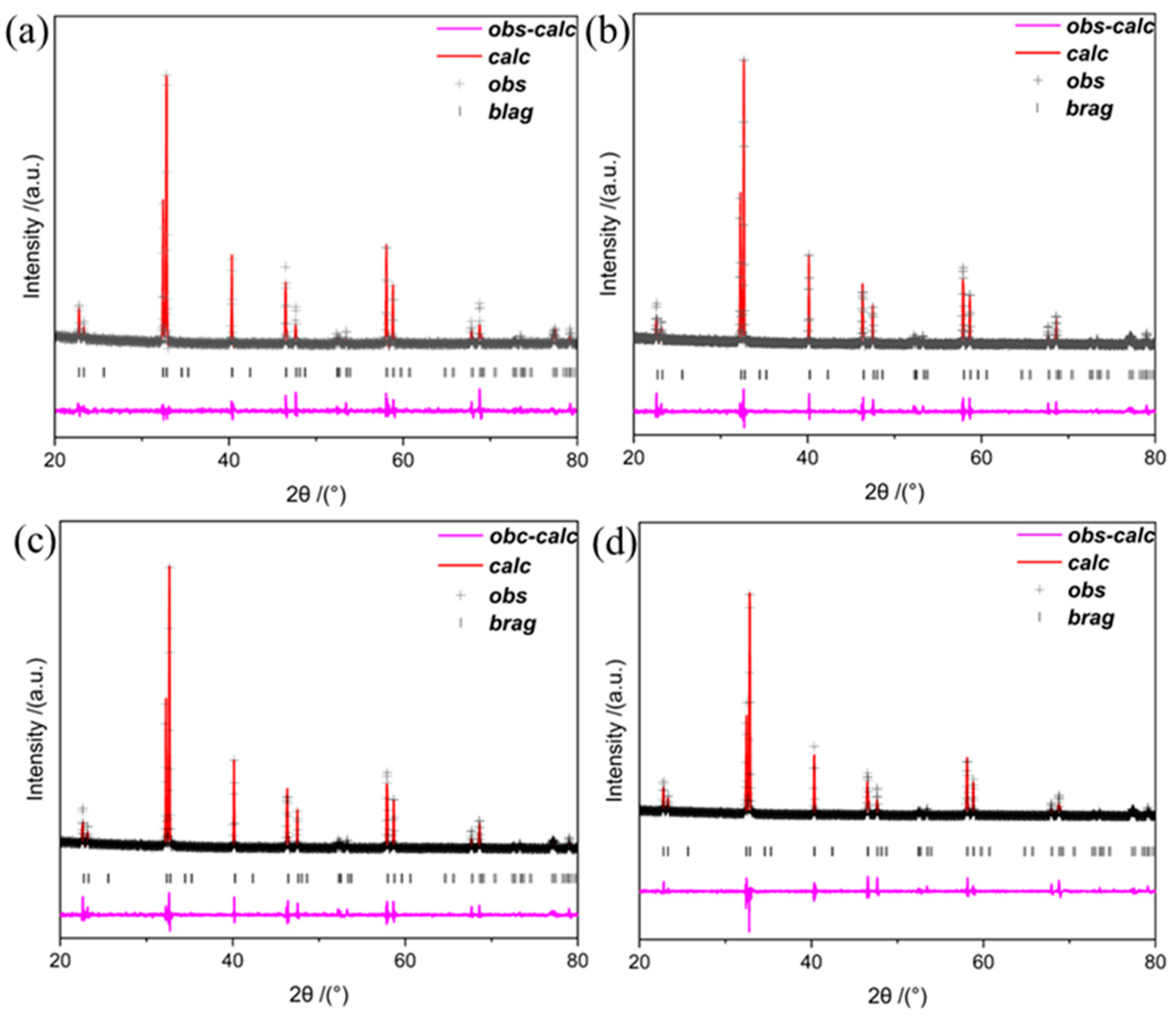
| Sample | Space Group | a (Å) | c (Å) | V (Å) | x2 | Rwp (%) | Rp (%) |
|---|---|---|---|---|---|---|---|
| PBC | P4/mmm | 3.903786 | 7.627325 | 116.237 | 2.02 | 9.68 | 7.77 |
| PBCN0.05 | P4/mmm | 3.909524 | 7.636684 | 116.722 | 2.39 | 8.93 | 7.91 |
| PBCN0.1 | P4/mmm | 3.912615 | 7.642894 | 117.002 | 2.45 | 9.87 | 8.30 |
| PBCN0.15 | P4/mmm | 3.914977 | 7.646315 | 117.195 | 2.50 | 9.47 | 8.09 |
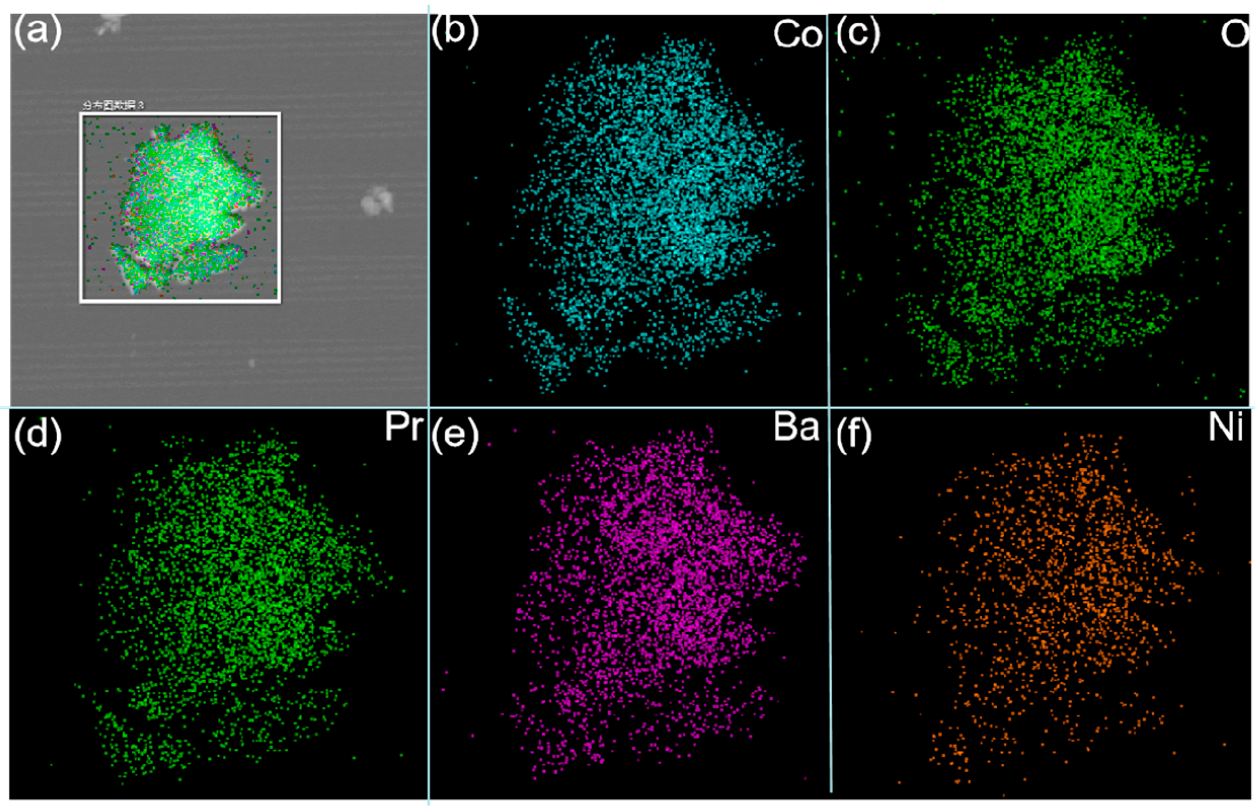
| Element | PBC Atom Ratio (%) | PBCNi0.1 Atom Ratio (%) |
|---|---|---|
| O | 61.37 | 61.29 |
| Co | 19.79 | 17.68 |
| Ni | - | 1.83 |
| Ba | 9.67 | 9.81 |
| Pr | 9.17 | 9.39 |
| Total | 100.00 | 100.00 |
| Sample | Electrolyte | Temperature (°C) | Rp (Ω·cm2) | TEC (K−1) (30–800 °C) | Reference |
|---|---|---|---|---|---|
| PBCF | LSGM | 700 | 0.221 | 21.0 × 10⁻⁶ | [22] |
| PBC | LSGM | 700 | 0.07 | 23.5 × 10⁻⁶ | [23] |
| LBSC | SDC | 800 | 0.081 | 26.2 × 10⁻⁶ | [24] |
| NBC | LSGM | 800 | 0.078 | 17.1 × 10⁻⁶ | [25] |
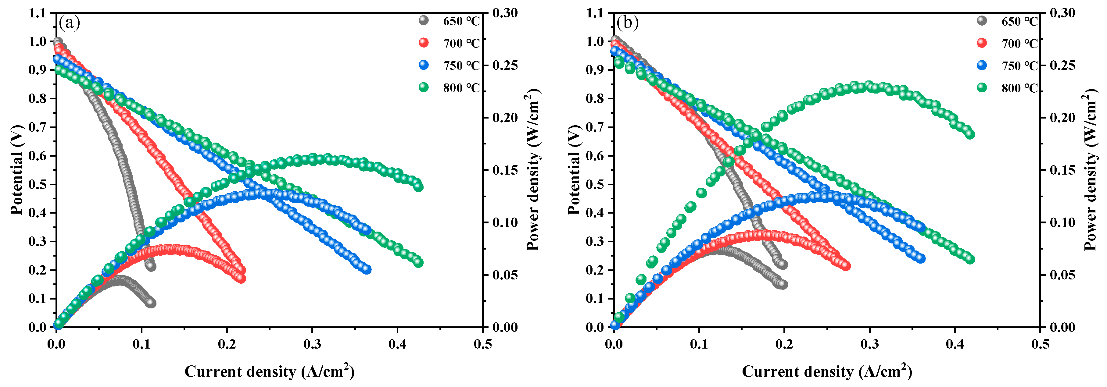
| PBCNi0.1 | SDC | 700 | 0.09 | 19.4837 × 10⁻⁶ | This work |
| PBCNi0.1 | SDC | 800 | 0.041 | 19.4837 × 10⁻⁶ | This work |
Disclaimer/Publisher’s Note: The statements, opinions and data contained in all publications are solely those of the individual author(s) and contributor(s) and not of MDPI and/or the editor(s). MDPI and/or the editor(s) disclaim responsibility for any injury to people or property resulting from any ideas, methods, instructions or products referred to in the content. |
© 2025 by the authors. Licensee MDPI, Basel, Switzerland. This article is an open access article distributed under the terms and conditions of the Creative Commons Attribution (CC BY) license (https://creativecommons.org/licenses/by/4.0/).
Share and Cite
Sun, R.; Li, S.; Gao, L.; An, S.; Yan, Z.; Cao, H.; Guo, Q.; Li, M. Ni-Doped Pr0.5Ba0.5CoO3+δ Perovskite with Low Polarization Resistance and Thermal Expansivity as a Cathode Material for Solid Oxide Fuel Cells. Molecules 2025, 30, 1482. https://doi.org/10.3390/molecules30071482
Sun R, Li S, Gao L, An S, Yan Z, Cao H, Guo Q, Li M. Ni-Doped Pr0.5Ba0.5CoO3+δ Perovskite with Low Polarization Resistance and Thermal Expansivity as a Cathode Material for Solid Oxide Fuel Cells. Molecules. 2025; 30(7):1482. https://doi.org/10.3390/molecules30071482
Chicago/Turabian StyleSun, Runze, Songbo Li, Lele Gao, Shengli An, Zhen Yan, Huihui Cao, Qiming Guo, and Mengxin Li. 2025. "Ni-Doped Pr0.5Ba0.5CoO3+δ Perovskite with Low Polarization Resistance and Thermal Expansivity as a Cathode Material for Solid Oxide Fuel Cells" Molecules 30, no. 7: 1482. https://doi.org/10.3390/molecules30071482
APA StyleSun, R., Li, S., Gao, L., An, S., Yan, Z., Cao, H., Guo, Q., & Li, M. (2025). Ni-Doped Pr0.5Ba0.5CoO3+δ Perovskite with Low Polarization Resistance and Thermal Expansivity as a Cathode Material for Solid Oxide Fuel Cells. Molecules, 30(7), 1482. https://doi.org/10.3390/molecules30071482