
Ballistic Impact Behaviour of Glass/Epoxy Composite Laminates Embedded with Shape Memory Alloy (SMA) Wires


Abstract

1. Introduction
2. Experimental Procedure
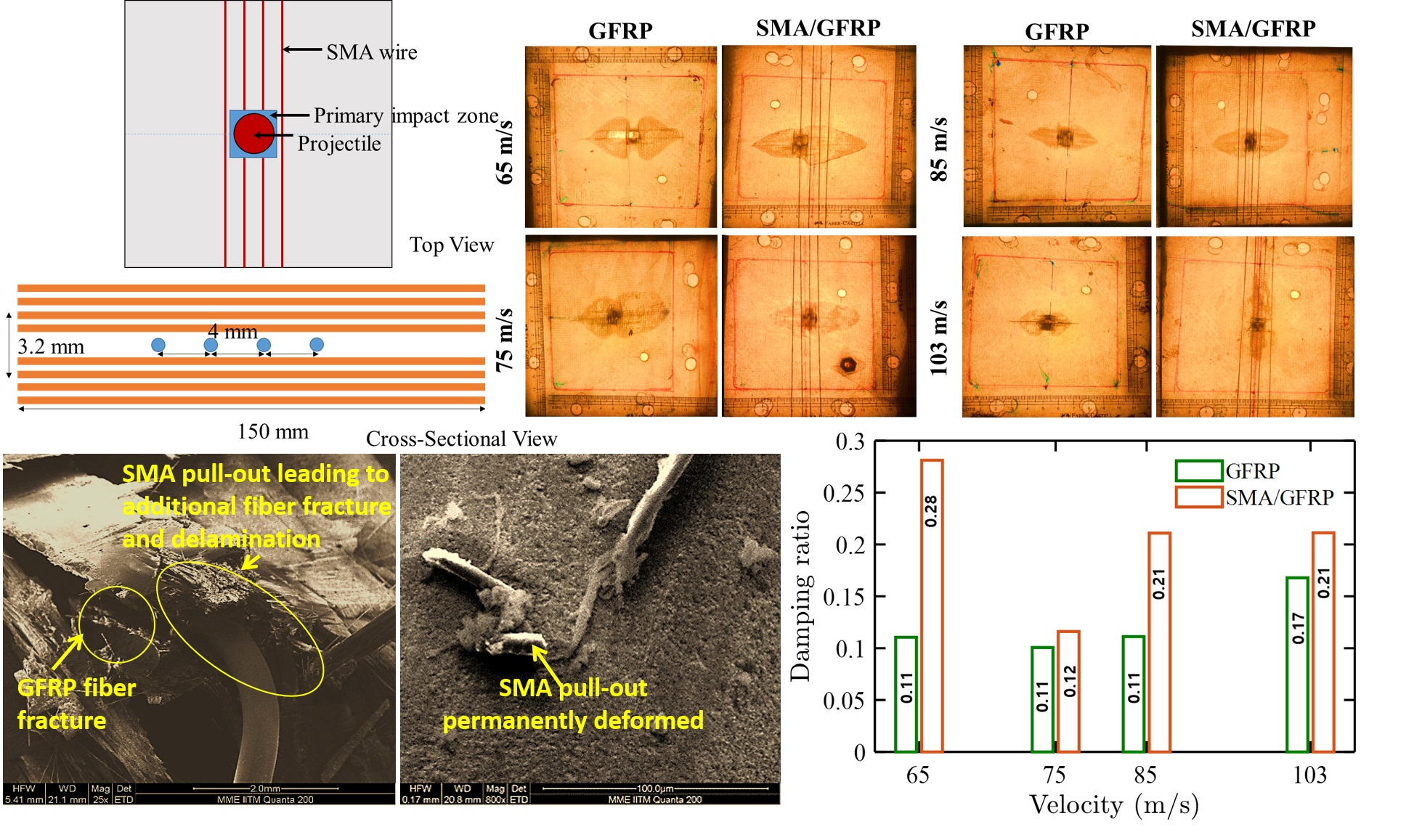
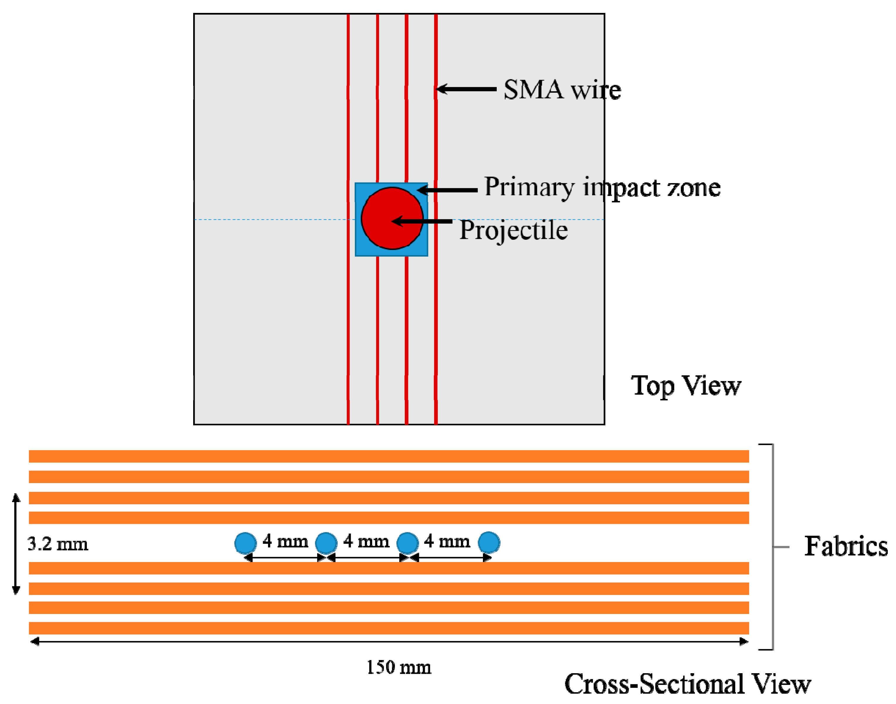
2.1. Materials and Fabrication
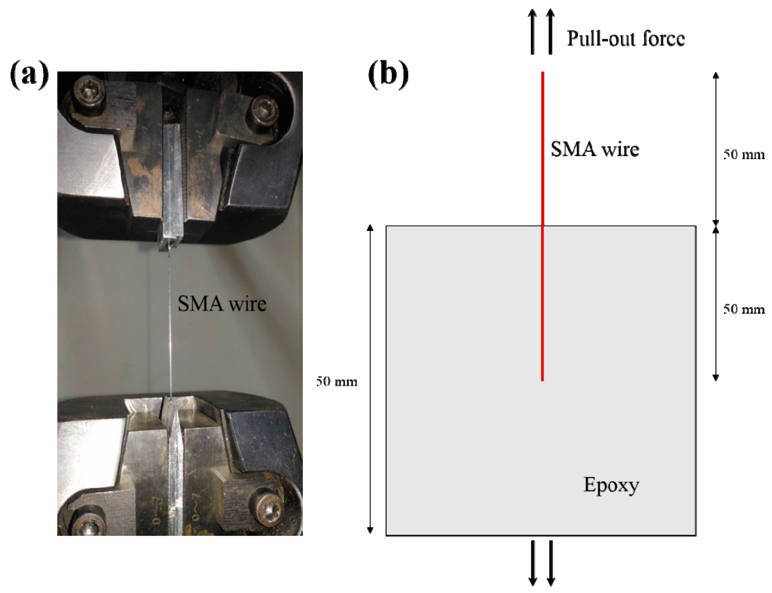
2.2. Quasistatic Tensile Test and SMA Pull-Out Test
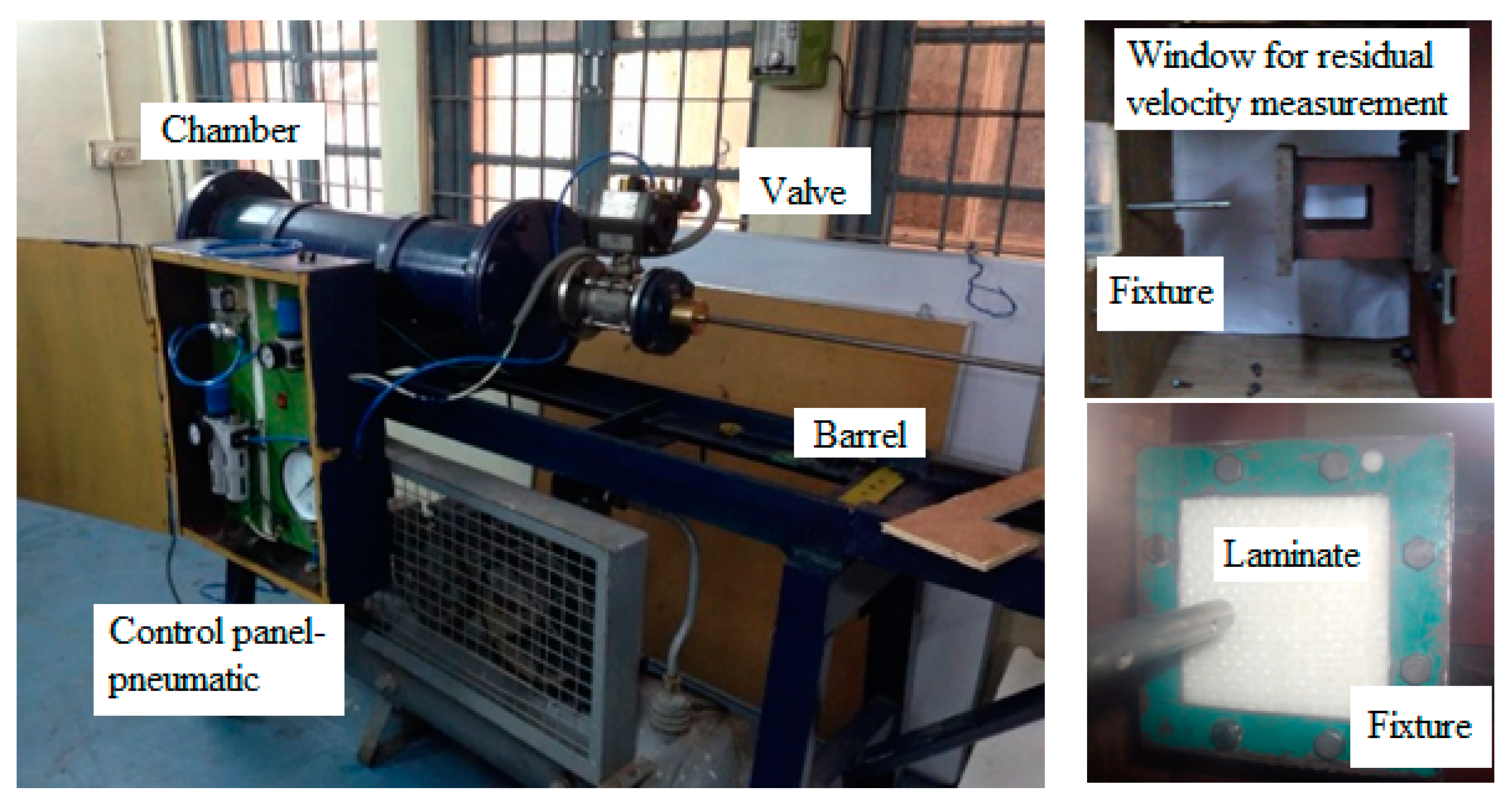
2.3. Gas-Gun Impact Test
2.4. Vibration Test
3. Results and Discussions
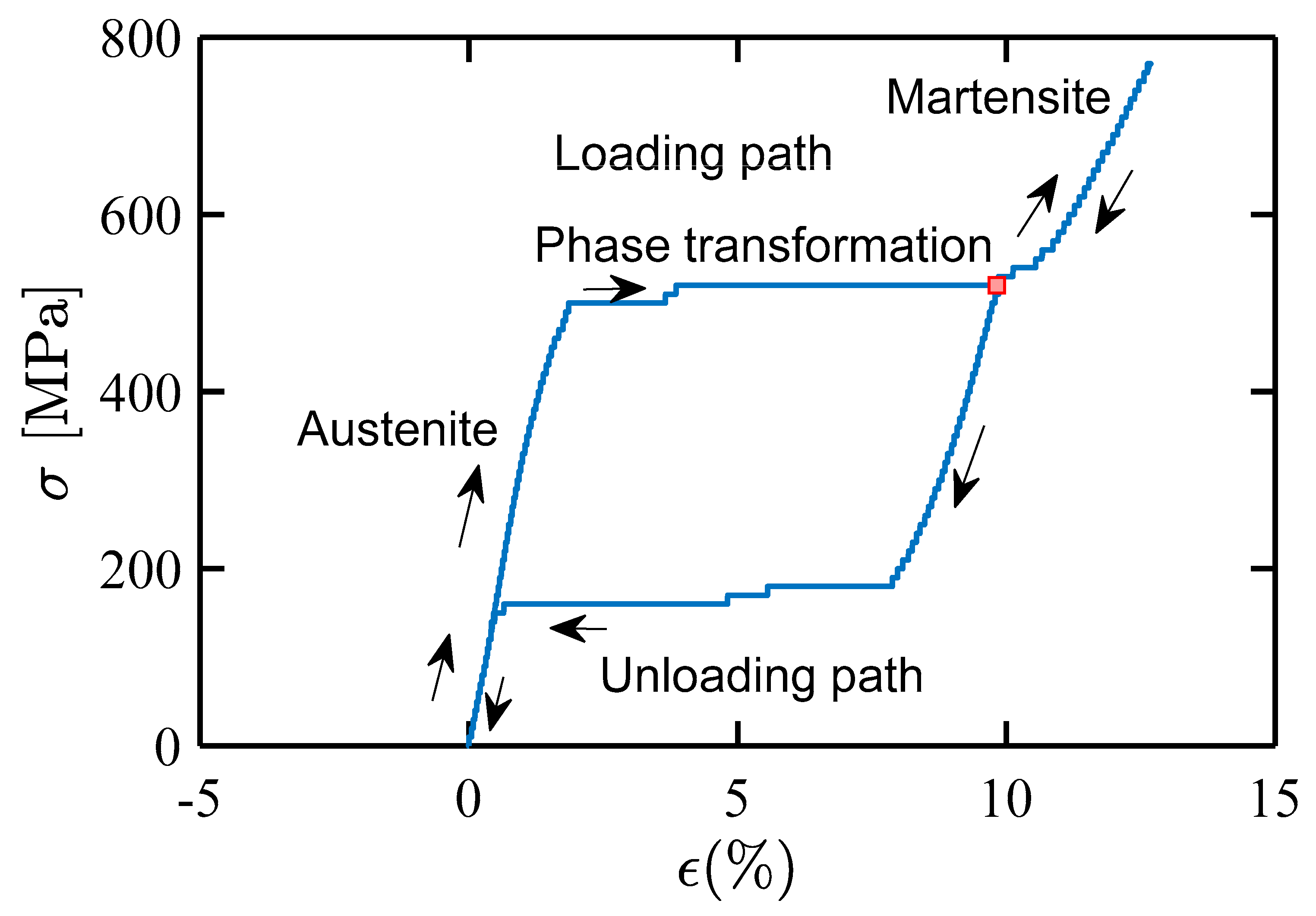
3.1. Quasistatic Tensile Response of Individual SMA Wire
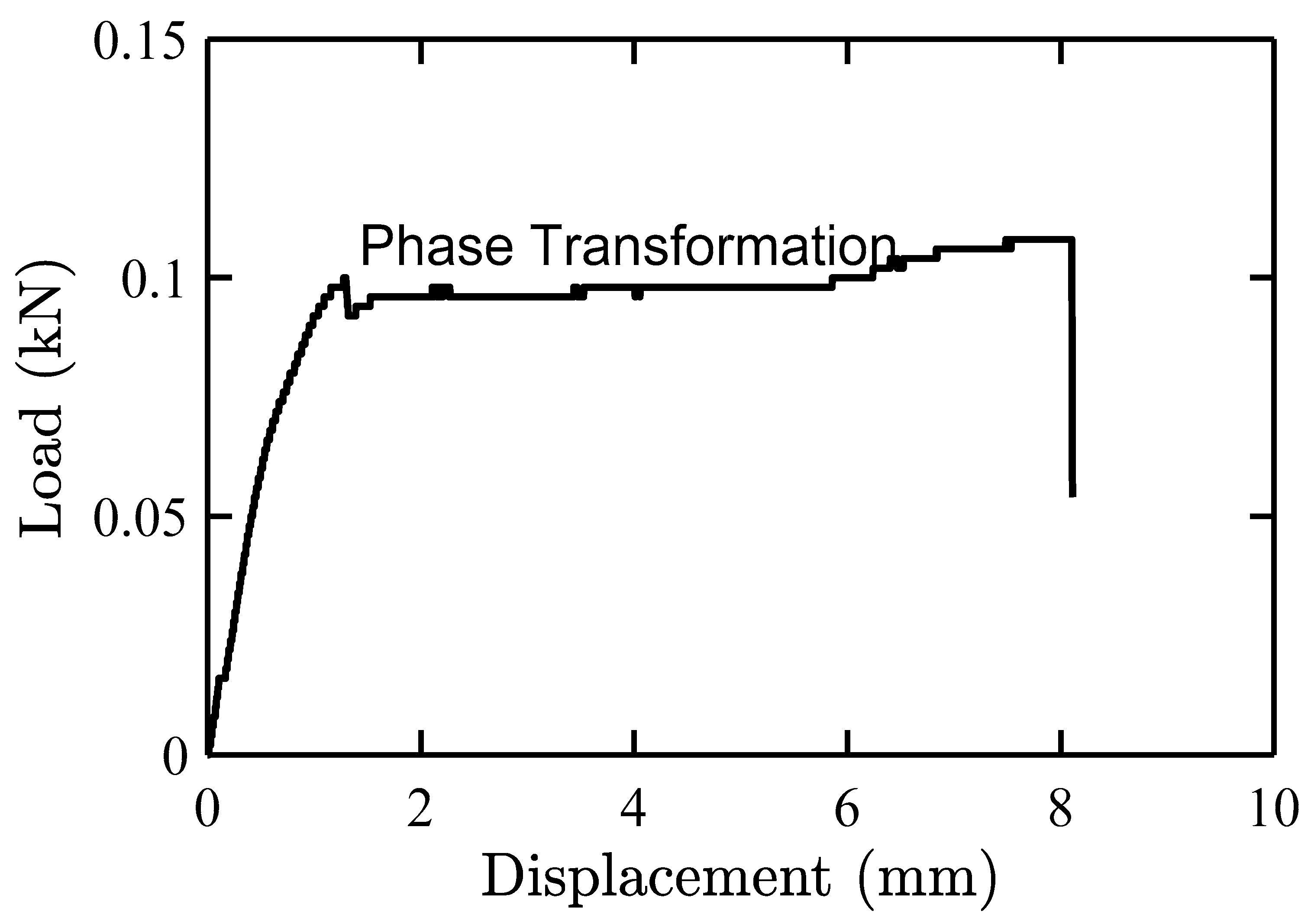
3.2. SMA/Epoxy Pull-Out Test
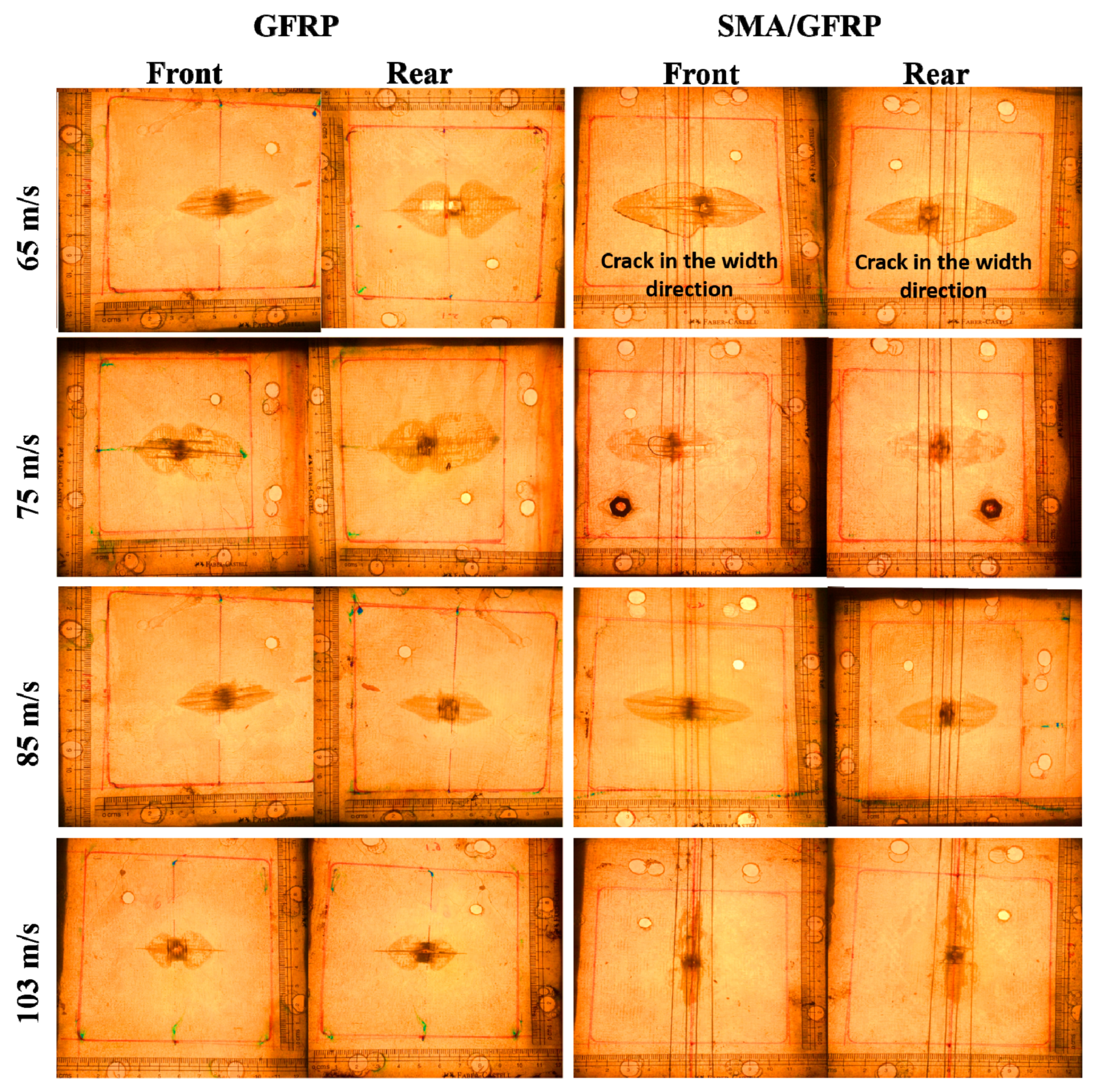
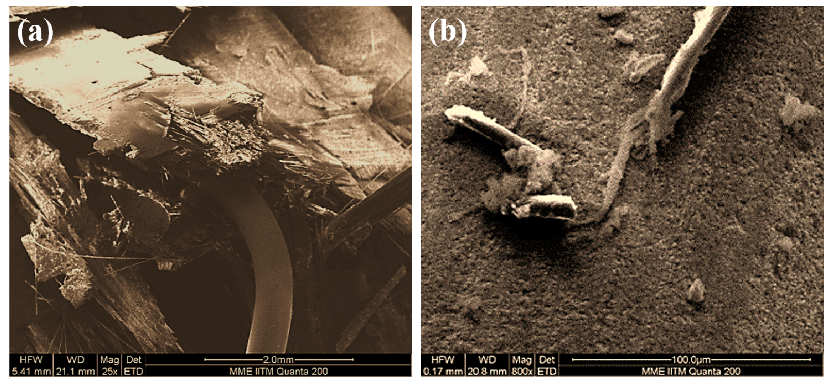
3.3. Gas-Gun Impact Test
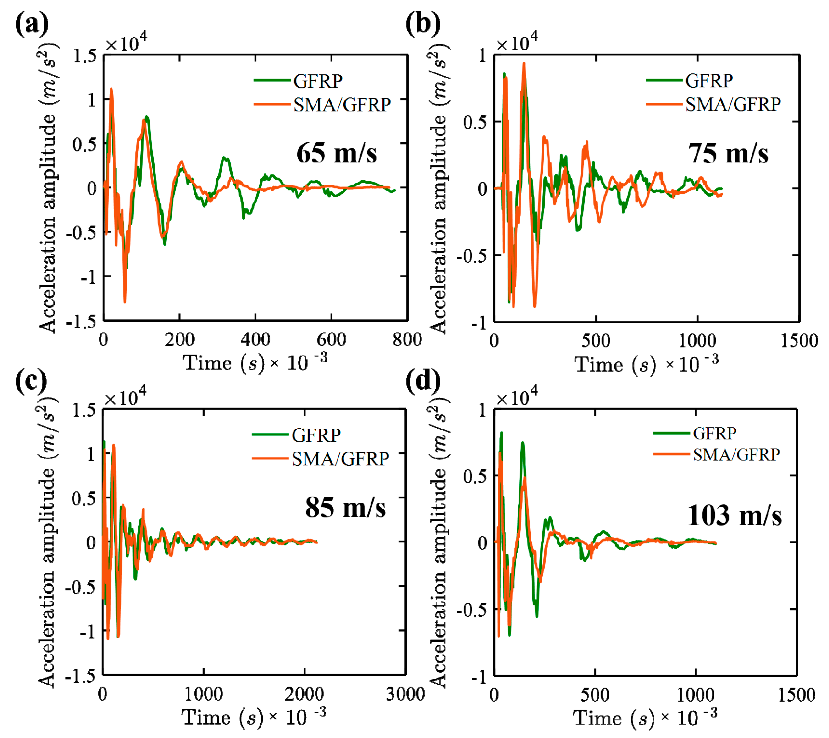
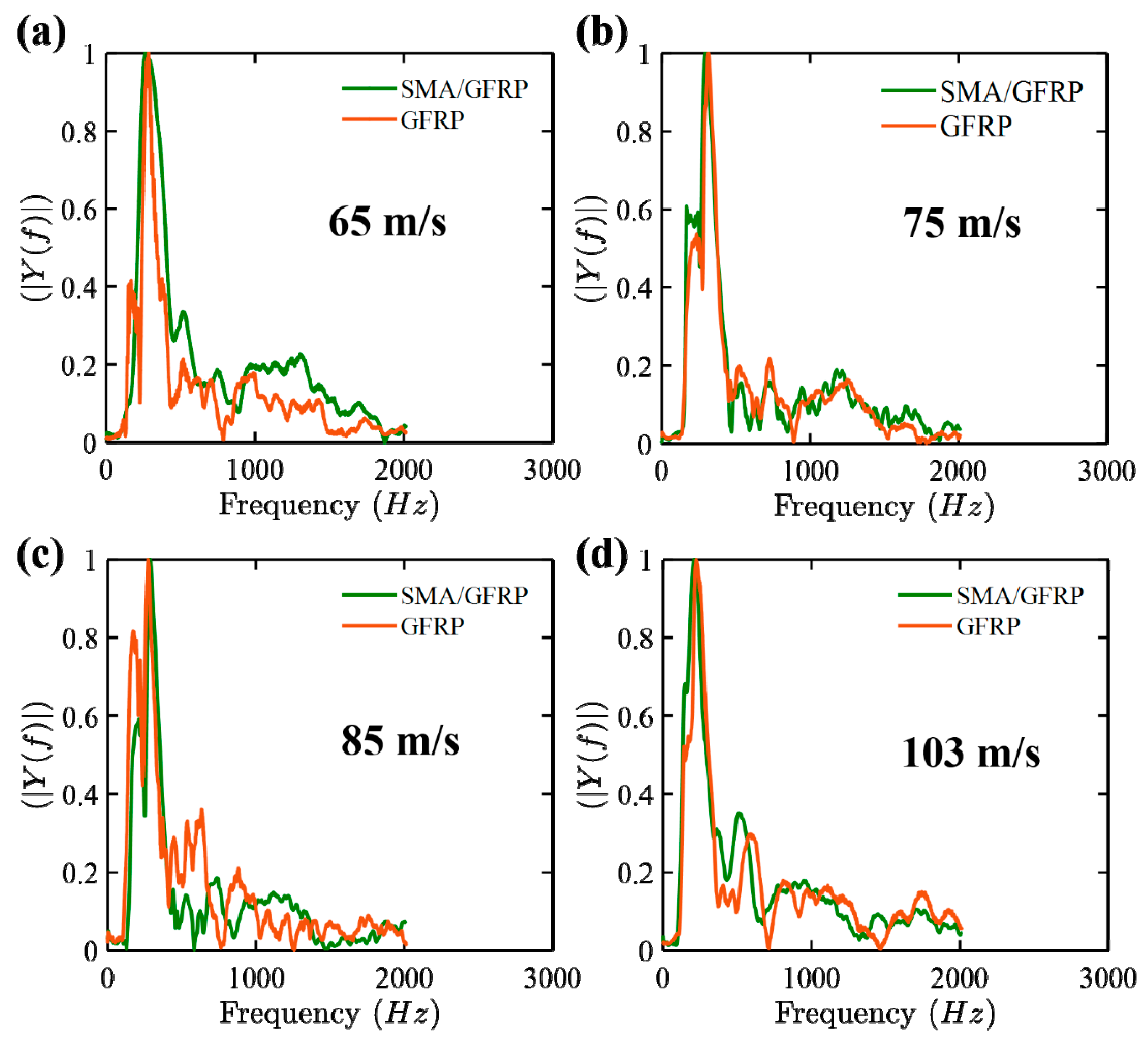
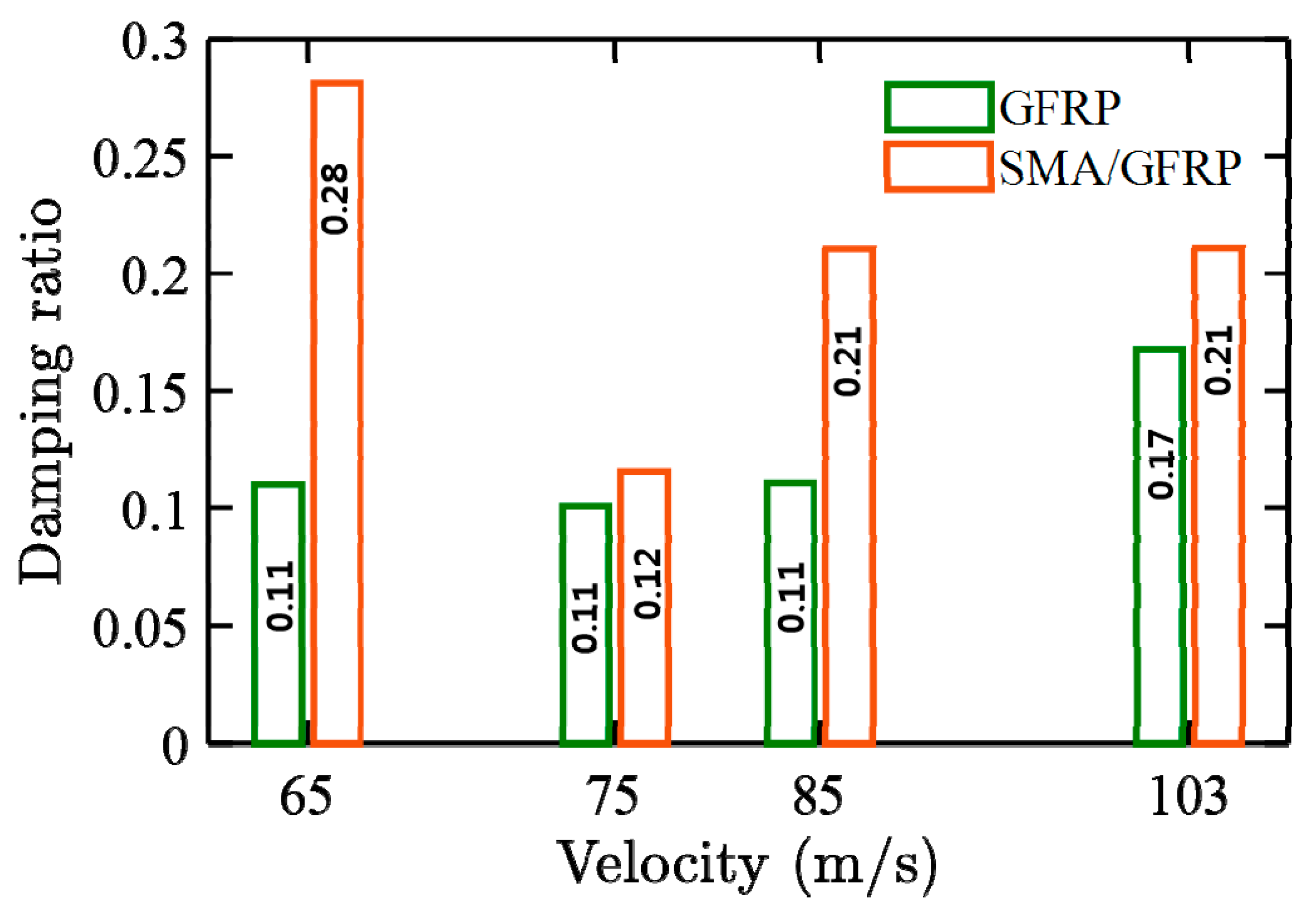
3.4. Energy Absorbtion in Vibration
4. Conclusions
Supplementary Materials
Author Contributions
Funding
Data Availability Statement
Conflicts of Interest
Sample Availability
References
- Andrew, J.J.; Srinivasan, S.M.; Arockiarajan, A.; Dhakal, H.N. Parameters influencing the impact response of fiber-reinforced polymer matrix composite materials: A critical review. Compos. Struct. 2019, 224, 111007. [Google Scholar] [CrossRef]
- Awal, M.A.; Kundu, T.; Joshi, S.P. Dynamic behavior of delamination and transverse cracks in fiber reinforced laminated composites. Eng. Fract. Mech. 1989, 33, 753–764. [Google Scholar] [CrossRef]
- Jefferson, A.J.; Srinivasan, S.M.; Arockiarajan, A. Effect of multiphase fiber system and stacking sequence on low-velocity impact and residual tensile behavior of glass/epoxy composite laminates. Polym. Compos. 2019, 40, 1450–1462. [Google Scholar] [CrossRef]
- Takeda, N.; Sierakowski, R.L.; Ross, C.A.; Malvern, L.E. Delamination-crack propagation in ballistically impacted glass/epoxy composite laminates. Exp. Mech. 1982, 22, 19–25. [Google Scholar] [CrossRef]
- Andrew, J.J.; Arumugam, V.; Ramesh, C.; Poorani, S.; Santulli, C. Quasi-static indentation properties of damaged glass/epoxy composite laminates repaired by the application of intra-ply hybrid patches. Polym. Test. 2017, 61, 132–145. [Google Scholar] [CrossRef]
- Verma, L.; Sivakumar, S.M.; Vedantam, S. Homogenization and Improvement in Energy Dissipation of Nonlinear Composites. In Behavior and Mechanics of Multifunctional Materials and Composites 2016; SPIE: Bellingham, WA, USA, 2016; Volume 9800, p. 980019. [Google Scholar]
- Wei, Z.; Sandstrom, R.; Miyazaki, S. Shape memory materials and hybrid composites for smart systems: Part II Shape-memory hybrid composites. J. Mater. Sci. 1998, 33, 3763–3783. [Google Scholar] [CrossRef]
- Quade, D.J.; Jana, S.C.; Morscher, G.N.; Kanaan, M. The effect of thin film adhesives on mode I interlaminar fracture toughness in carbon fiber composites with shape memory alloy inserts. Eng. Fract. Mech. 2019, 206, 131–146. [Google Scholar] [CrossRef] [PubMed]
- Shimamoto, A.; Ohkawara, H.; Nogata, F. Enhancement of mechanical strength by shape memory effect in TiNi fiber-reinforced composites. Eng. Fract. Mech. 2004, 71, 737–746. [Google Scholar] [CrossRef]
- Kiesling, T.; Chaudhry, Z.; Paine, J.; Rogers, C. Impact failure modes of thin graphite epoxy composites embedded with superelastic nitinol. In Proceedings of the 37th Structure, Structural Dynamics and Materials Conference, Salt Lake City, UT, USA, 15–17 April 1996; p. 1475. [Google Scholar]
- Tsoi, K.A.; Stalmans, R.; Schrooten, J.; Wevers, M.; Mai, Y.-W. Impact damage behaviour of shape memory alloy composites. Mater. Sci. Eng. A 2003, 342, 207–215. [Google Scholar] [CrossRef]
- Meo, M.; Marulo, F.; Guida, M.; Russo, S. Shape memory alloy hybrid composites for improved impact properties for aeronautical applications. Compos. Struct. 2013, 95, 756–766. [Google Scholar] [CrossRef]
- Angioni, S.; Meo, M.; Foreman, A. Impact damage resistance and damage suppression properties of shape memory alloys in hybrid composites—A review. Smart Mater. Struct. 2010, 20, 013001. [Google Scholar] [CrossRef]
- Raghavan, J.; Bartkiewicz, T.; Boyko, S.; Kupriyanov, M.; Rajapakse, N.; Yu, B. Damping, tensile, and impact properties of superelastic shape memory alloy (SMA) fiber-reinforced polymer composites. Compos. Part B Eng. 2010, 41, 214–222. [Google Scholar] [CrossRef]
- Zhang, R.-x.; Ni, Q.-Q.; Masuda, A.; Yamamura, T.; Iwamoto, M. Vibration characteristics of laminated composite plates with embedded shape memory alloys. Compos. Struct. 2006, 74, 389–398. [Google Scholar] [CrossRef]
- Birman, V.; Chandrashekhara, K.; Sain, S. An approach to optimization of shape memory alloy hybrid composite plates subjected to low-velocity impact. Compos. Part B Eng. 1996, 27, 439–446. [Google Scholar] [CrossRef]
- Lau, K.-T.; Ling, H.-Y.; Zhou, L.-M. Low velocity impact on shape memory alloy stitched composite plates. Smart Mater. Struct. 2004, 13, 364. [Google Scholar] [CrossRef]
- Schwartz, M. New Materials, Processes, and Methods Technology; CRC Press: Boca Raton, FL, USA, 2005. [Google Scholar]
- Paine, J.; Rogers, C. High Velocity Impact Response of Composites with Surface Bonded Nitinol-SMA Hybrid Layers. In Proceedings of the 36th Structures, Structural Dynamics and Materials Conference, New Orleans, LA, USA, 10–13 April 1995. [Google Scholar] [CrossRef]
- Verma, L.; Sivakumar, S.M.; Andrew, J.J.; Balaganesan, G.; Arockirajan, A.; Vedantam, S. Compression after ballistic impact response of pseudoelastic shape memory alloy embedded hybrid unsymmetrical patch repaired glass-fiber reinforced polymer composites. J. Compos. Mater. 2019, 53, 4225–4247. [Google Scholar] [CrossRef]
- Naik, N.K.; Shrirao, P.; Reddy, B.C.K. Ballistic impact behaviour of woven fabric composites: Formulation. Int. J. Impact Eng. 2006, 32, 1521–1552. [Google Scholar] [CrossRef]
- Verma, L.; Sivakumar, M.S.; Balaganesan, G.; Vedantam, S. Energy dissipation studies of SMA reinforced composites under multiple quasi-static indentation loading. Mech. Adv. Mater. Struct. 2019, 26, 2–5. [Google Scholar] [CrossRef]
- Andrew, J.J.; Srinivasan, S.M.; Arockiarajan, A. The role of adhesively bonded super hybrid external patches on the impact and post-impact response of repaired glass/epoxy composite laminates. Compos. Struct. 2018, 184, 848–859. [Google Scholar] [CrossRef]
- Bhoominathan, R.; Arumugam, V.; Ashok, T.; Jefferson, A.J. Residual strength estimation of CFRP laminates subjected to impact at different velocities and temperatures. Polym. Compos. 2017, 38, 2182–2191. [Google Scholar] [CrossRef]
- Verma, L.; Andrew, J.J.; Sivakumar, S.M.; Balaganesan, G.; Vedantam, S.; Dhakal, H.N. Compression after high-velocity impact behavior of pseudo-elastic shape memory alloy embedded glass/epoxy composite laminates. Compos. Struct. 2020. In Press. [Google Scholar] [CrossRef]
- Verma, L.; Andrew, J.J.; Sivakumar, S.M.; Balaganesan, G.; Vedantam, S.; Dhakal, H.N. Evaluation of quasi-static indentation response of superelastic shape memory alloy embedded GFRP laminates using AE monitoring. Polym. Test. 2020, 106942. [Google Scholar] [CrossRef]
- Morye, S.; Hine, P.; Duckett, R.; Carr, D.; Ward, I. Modelling of the energy absorption by polymer composites upon ballistic impact. Compos. Sci. Technol. 2000, 60, 2631–2642. [Google Scholar] [CrossRef]
- Jefferson Andrew, J.; Arumugam, V.; Bull, D.J.; Dhakal, H.N. Residual strength and damage characterization of repaired glass/epoxy composite laminates using A.E. and D.I.C. Compos. Struct. 2016, 152, 124–139. [Google Scholar] [CrossRef]
- Andrew, J.J.; Arumugam, V.; Santulli, C. Effect of post-cure temperature and different reinforcements in adhesive bonded repair for damaged glass/epoxy composites under multiple quasi-static indentation loading. Compos. Struct. 2016, 143, 63–74. [Google Scholar] [CrossRef]
- Bhatia, G.S.; Andrew, J.J.; Balaganesan, G.; Arockiarajan, A. The role of patch-parent configurations on the tensile response of patch repaired carbon/epoxy laminates. Polym. Test. 2018, 70, 413–425. [Google Scholar] [CrossRef]
- Nemat-Nasser, S.; Guo, W.G. Superelastic and cyclic response of NiTi SMA at various strain rates and temperatures. Mech. Mater. 2006, 38, 463–474. [Google Scholar] [CrossRef]
- DiFrancia, C.; Ward, T.C.; Claus, R.O. The single-fibre pull-out test. 1: Review and interpretation. Compos. Part A Appl. Sci. Manuf. 1996, 27, 597–612. [Google Scholar] [CrossRef]
- Andrew, J.J.; Srinivasan, S.M.; Arockiarajan, A. Influence of patch lay-up configuration and hybridization on low velocity impact and post-impact tensile response of repaired glass fiber reinforced plastic composites. J. Compos. Mater. 2019, 53, 3–17. [Google Scholar] [CrossRef]
- Andrew, J.J.; Arumugam, V.; Dhakal, H.N. Effect of Intra-Ply Hybrid Patches and Hydrothermal Aging on Local Bending Response of Repaired GFRP Composite Laminates. Molecules 2020, 25, 2325. [Google Scholar] [CrossRef]
- Andrew, J.J.; Arumugam, V.; Ramesh, C. Acoustic emission based monitoring of cut-out geometry effects incarbon/epoxy laminates under uni-axial compression. Int. J. Veh. Struct. Syst. 2014, 6, 17. [Google Scholar]
- Ghelli, D.; Minak, G. Low velocity impact and compression after impact tests on thin carbon/epoxy laminates. Compos. Part B Eng. 2011, 42, 2067–2079. [Google Scholar] [CrossRef]
- Andrew, J.; Ramesh, C. Residual Strength and Damage Characterization of Unidirectional Glass–BasaltHybrid/Epoxy CAI Laminates. Arab. J. Sci. Eng. 2015, 40, 1695–1705. [Google Scholar] [CrossRef]
- Andrew, J.J.; Arumugam, V.; Ramesh, C. Acoustic emission characterization of local bending behavior foradhesively bonded hybrid external patch repaired glass/epoxy composite laminates. Struct. Health Monit. 2019, 18, 739–756. [Google Scholar] [CrossRef]
- Jefferson, A.; Arumugam, V.; Santulli, C.; Jennifers, A.; Poorani, M. Failure modes of GFRP after multiple impacts determined by acoustic emission and digital image correlation. J. Eng. Technol. 2015, 6, 29–51. [Google Scholar]
- Starratt, D.; Sanders, T.; Cepuš, E.; Poursartip, A.; Vaziri, R. An efficient method for continuous measurement of projectile motion in ballistic impact experiments. Int. J. Impact Eng. 2000, 24, 155–170. [Google Scholar] [CrossRef]
- Li, T.; Yang, Y.; Yu, X.; Liu, H.; Li, Y. Micro-structure response and fracture mechanisms of C/SiC composites subjected to low-velocity ballistic penetration. Ceram. Int. 2017, 43, 6910–6918. [Google Scholar] [CrossRef]
- Sahu, P.; Sharma, N.; Panda, S.K. Numerical prediction and experimental validation of free vibration responses of hybrid composite (Glass/Carbon/Kevlar) curved panel structure. Compos. Struct. 2020, 241, 112073. [Google Scholar] [CrossRef]


| Properties | Values (PE-SMA) | Units |
|---|---|---|
| Austenite Young’s modulus (Eaus) | 80 | GPa |
| Martensite Young’s modulus (Emar) | 40 | GPa |
| Poisson’s ratio | 0.3 | - |
| Density | 6800 | Kg-m3 |
| Yield stress | 800 | MPa |
| Properties | Values (PE-SMA) | Units |
|---|---|---|
| Young’s modulus | 76.6 | GPa |
| Specific modulus | 0.0340 | GPa-m3/Kg |
| Specific strength | 0.6200 | MPa-m3/Kg |
| Poisson’s ratio | 0.25 | - |
| Properties | Values | Units |
|---|---|---|
| Specific gravity | 1.28 | - |
| Young’s modulus | 3.792 | GPa |
| Poisson’s ratio | 0.30 | - |
| Impact Velocities (m/s) | Total-Pull Out Length (mm) |
|---|---|
| 60 | 18 |
| 75 | 30 |
| 85 | 12 |
| 103 | 4 |
| Initial Velocity (m/s) | 65 | 75 | 85 | 103 |
| Residual Velocity (GFRP, m/s) | 0 | 44.2 | 62.2 | 87.2 |
| Residual Velocity (SMA/GFRP, m/s) | −5 | 20 | 50.6 | 83.3 |
| Velocity (m/s) | Maximum Acceleration (m2/s) | |
|---|---|---|
| GFRP Specimens | SMA/GFRP Specimens | |
| 65 | 1.12 × 10⁴ | 9.4 × 10³ |
| 75 | 9.34 × 10³ | 8.5 × 10³ |
| 85 | 1.13 × 10⁴ | 1.09 × 10⁴ |
| 103 | 8.22 × 10³ | 6.71 × 10³ |
Publisher’s Note: MDPI stays neutral with regard to jurisdictional claims in published maps and institutional affiliations. |
© 2020 by the authors. Licensee MDPI, Basel, Switzerland. This article is an open access article distributed under the terms and conditions of the Creative Commons Attribution (CC BY) license (http://creativecommons.org/licenses/by/4.0/).
Share and Cite
Verma, L.; Andrew, J.; Sivakumar, S.M.; Balaganesan, G.; Vedantam, S.; Dhakal, H.N. Ballistic Impact Behaviour of Glass/Epoxy Composite Laminates Embedded with Shape Memory Alloy (SMA) Wires. Molecules 2021, 26, 138. https://doi.org/10.3390/molecules26010138
Verma L, Andrew J, Sivakumar SM, Balaganesan G, Vedantam S, Dhakal HN. Ballistic Impact Behaviour of Glass/Epoxy Composite Laminates Embedded with Shape Memory Alloy (SMA) Wires. Molecules. 2021; 26(1):138. https://doi.org/10.3390/molecules26010138
Chicago/Turabian StyleVerma, Luv, Jefferson Andrew, Srinivasan M. Sivakumar, Gurusamy Balaganesan, Srikanth Vedantam, and Hom N. Dhakal. 2021. "Ballistic Impact Behaviour of Glass/Epoxy Composite Laminates Embedded with Shape Memory Alloy (SMA) Wires" Molecules 26, no. 1: 138. https://doi.org/10.3390/molecules26010138
APA StyleVerma, L., Andrew, J., Sivakumar, S. M., Balaganesan, G., Vedantam, S., & Dhakal, H. N. (2021). Ballistic Impact Behaviour of Glass/Epoxy Composite Laminates Embedded with Shape Memory Alloy (SMA) Wires. Molecules, 26(1), 138. https://doi.org/10.3390/molecules26010138