Technical Note

Design, Production and Evaluation of 3D-Printed Mold Geometries for a Hybrid Rocket Engine

1
Institute of Space Systems (IRAS), Technische Universität Braunschweig (TUBS), 38108 Braunschweig, Germany
2
Chair of Space Technology, Technical University of Berlin, 10587 Berlin, Germany
*
Author to whom correspondence should be addressed.
These authors contributed equally to this work.
Aerospace 2021, 8(8), 220; https://doi.org/10.3390/aerospace8080220
Submission received: 10 June 2021 / Revised: 20 July 2021 / Accepted: 2 August 2021 / Published: 8 August 2021
(This article belongs to the Special Issue Hybrid Rocket(Volume II))

Abstract

:
The feasibility of 3D-printed molds for complex solid fuel block geometries of hybrid rocket engines is investigated. Additively produced molds offer more degrees of freedom in designing an optimized but easy to manufacture mold. The solid fuel used for this demonstration was hydroxyl-terminated polybutadiene (HTPB). Polyvinyl alcohol (PVA) was chosen as the mold material due to its good dissolving characteristics. It is shown that conventional and complex geometries can be produced reliably with the presented methods. In addition to the manufacturing process, this article presents several engine tests with different fuel grain geometries, including a short overview of the test bed, the engine and first tests.

1. Introduction

A hybrid rocket engine uses a combination of a solid and a liquid propellant. It unites some advantages of liquid rocket engines (e.g., possibility to control the burn time) and those of solid rocket motors (e.g., simple combustion chamber design); however, one major inherent disadvantage of most hybrid engines is a low regression rate of the fuel grain, which means that only a moderate thrust can be achieved. Most hybrid fuel combinations show a regression rate in the range of 0.8 to 5 mm/s [1]. While common solid rocket motor fuels are nearly a magnitude superior to hybrids and are in the range of 6 to 40 mm/s. Different approaches were made to resolve this issue. Besides changing the solid fuel itself, modifications can be made to the fuel grain surface and geometry. In order to achieve a higher regression rate with common fuel block manufacturing, multiple grains with different geometries or geometrical orientations can be stacked. Examples are stepped fuel blocks [2] or multiport geometries, which are rotated against each other [3,4,5]. The disadvantage of such methods is the inconsistent regression rate over the fuel block length due to higher regression rates only occurring in vortex areas [2,4,5]. Common ways to create a geometry of the fuel grain are limited to a constant shape over the fuel block length due to manufacturing effort. If the base material of the fuel grain is solid, those fuel blocks can be produced by a machine. If the base material is a liquid that cures under temperature to a solid block, a removable mold is required. Common methods are molds made of coated metals with a release agent or disposable molds made of styrofoam, which are decomposed by a solvent. With the availability of additive manufacturing, the production of more complex fuel geometries is possible. Increased freedom in the grain design can be used to achieve higher regression rates through a flow-optimized geometry. Besides a higher regression rate [6,7,8,9], a monolithic fuel block can be achieved. In this article, a new approach with a flow-optimized and additive manufactured disposable mold was investigated. HTPB and nitrous oxide (N 2 O) were chosen as fuel and oxidant, respectively; both components offer simple handling and are therefore ideal for use in research. The advantages of HTPB comprise 20 years of experience at the Institute of Space Systems (IRAS) and its suitable chemical and mechanical properties for rocketry [10]. The raw material is supplied as a liquid that is cured to a stiff rubber-like material by a hardener. Furthermore, the combination of hydroxyl-terminated polybutadiene (HTPB) and N 2 O achieves a moderate specific impulse (ISP) up to 2400 m/s [11] at 3.5 MPa chamber pressure and an expansion ratio of 5.2. To demonstrate the possibilities of an additively manufactured disposable mold, a flow-optimized geometry was developed and produced. A fused deposition modeling (FDM) 3D printer was utilized to fabricate the complex mold geometry. Polyvinyl alcohol (PVA) was selected as print material because of its good dissolving properties in water. This approach was chosen because it offers the capability to produce any relevant kind of shape. At the same time, the glass transition temperature of PVA (88 °C [12]) is slightly above the used curing temperature of HTPB, which makes it sufficient as a molding material. In accordance to the literature, curing of HTPB with isophorone diisocyanate (IPDI) as the curative and dibutylzinn-dilaurat (DBTDL) as catalyst is performed at 60 °C for seven days [13,14].

2. Materials and Methods

To improve the low thrust of hybrid rocket engines, new approaches have to be found. By changing the fuel block geometry to a more flow-optimized shape, the material properties can be maintained while increasing the regression rate [6]. Such optimized fuel block shapes require complex molds.

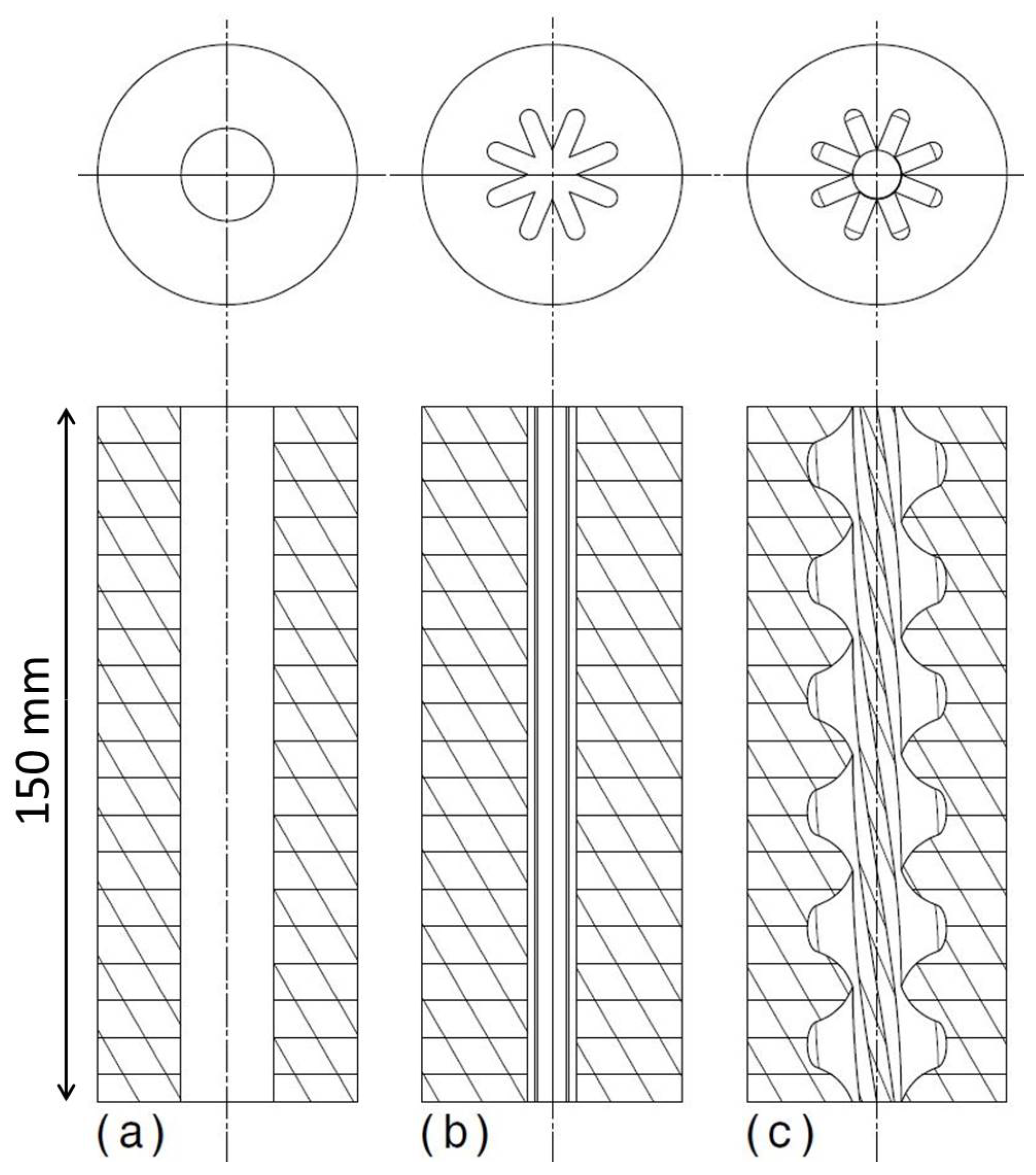
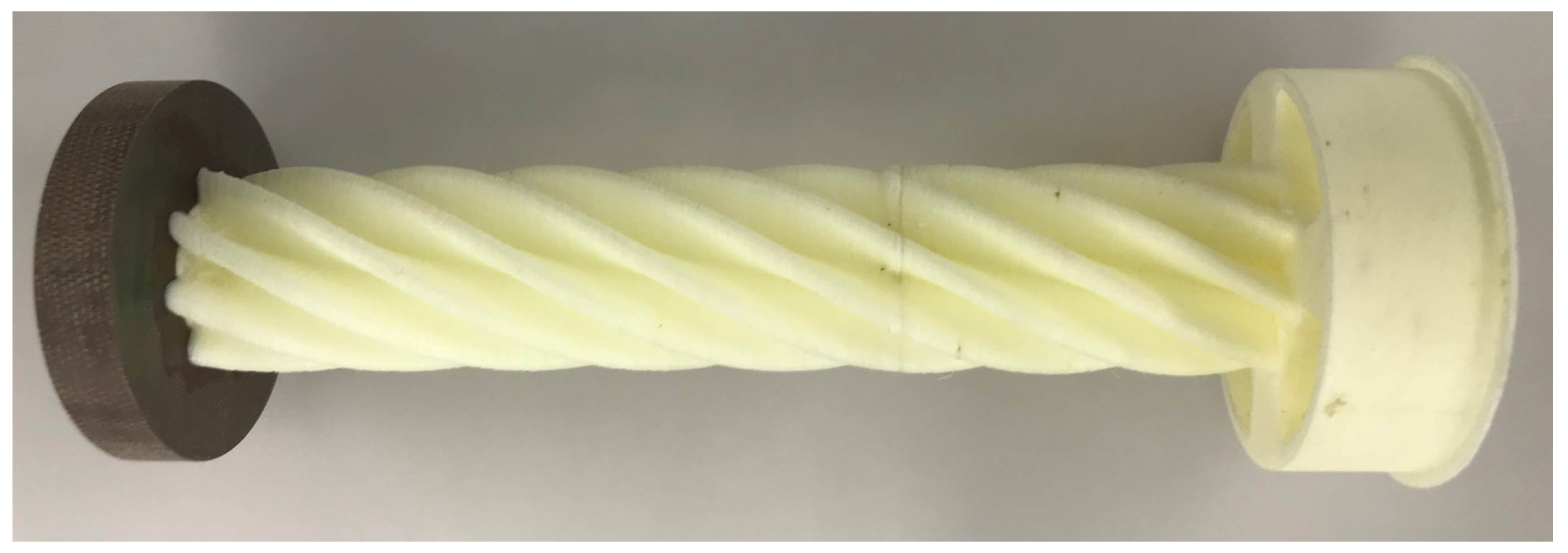
2.1. Solid Fuel Block Geometries

In order to compare the flow-optimized geometry to common geometries, two further grain shapes were selected for manufacturing and testing, the Monoport and star geometry. All three geometries are illustrated in Figure 1. The Monoport is a simple cylinder selected for reference and mold process tests. Because of its low thrust and long burn time compared to the other two geometries, it is well suited for the first engine tests. The second geometry is star shaped, which is a common fuel grain cross section for solid rocket motors if a higher mass flow and thereby thrust is required. The flow-optimized fuel grain is a star twisted 360 helically along the engine axis, which was tested as the third geometry and is therefore ideal suited for comparison. A detailed cross-section view is presented in Figure 2. According to simulations by the Institute of Aerodynamics and Flow Technology (AS) from the German Aerospace Center (DLR) in Brunswick [7], this twisted geometry doubles the regression rate and thus the thrust while keeping the surface area nearly constant.

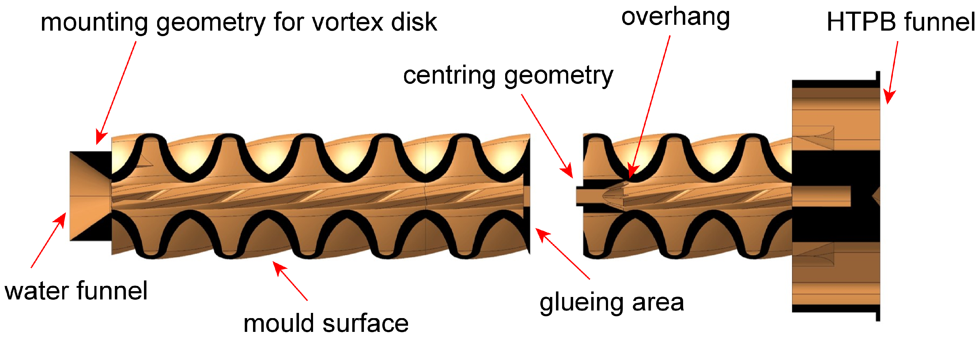
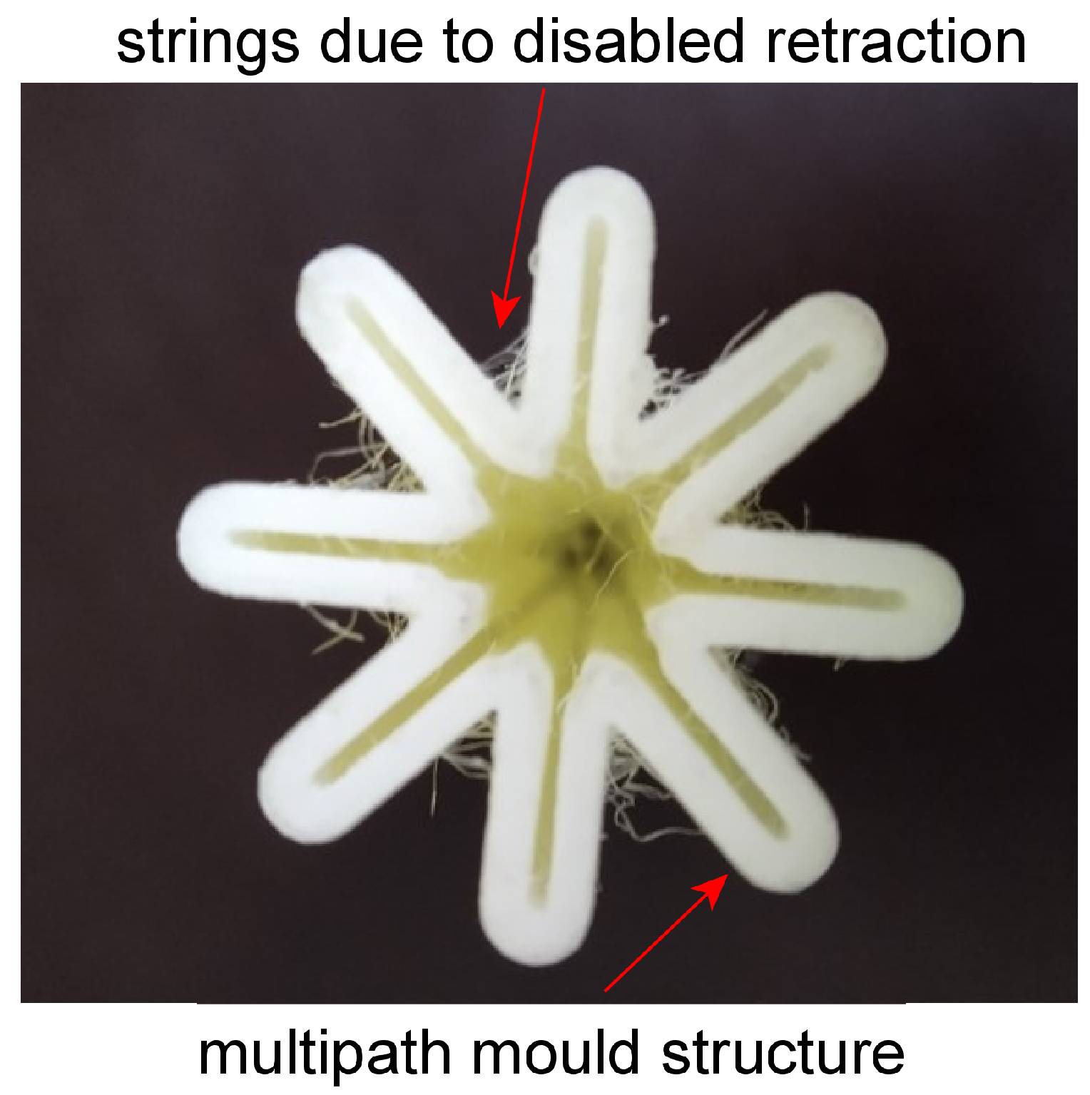
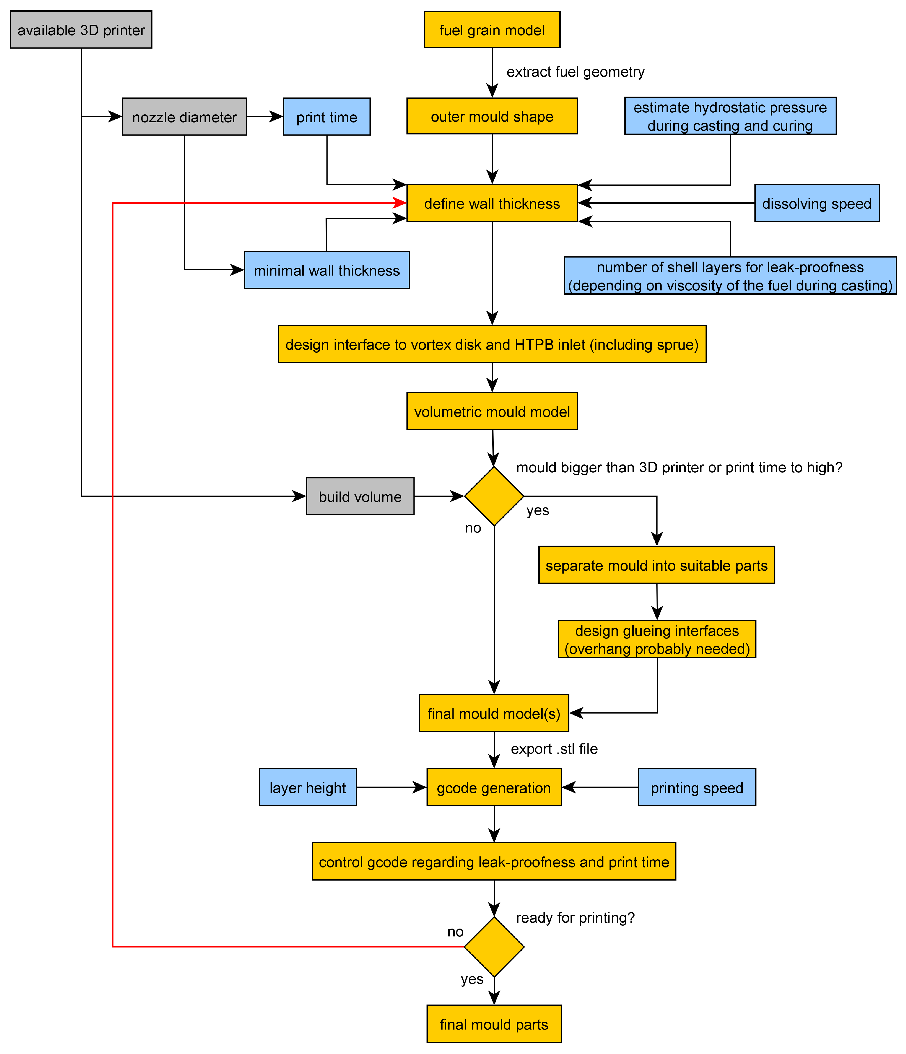
2.1.1. Mold Design and Printing

The design of the mold depends on the available printer. An Ultimaker 2 Extended (manufactured by Ultimaker B.V., Netherlands) with a 0.6 mm nozzle orifice and commercial 2.85 mm PVA was used. Several design aspects, which are listed in Table 1, were considered. The result was a mold design that was heavily influenced by the mold wall thickness. A thin wall has the advantage of fast dissolving speeds and less PVA consumption and print time, but the structural integrity and leak-proofness are at risk. Furthermore the nozzle size of the FDM printer has to be considered in the process of mold designing in order to avoid unprintable parts. A detailed flow chart of this design process is presented in Figure A1, Appendix A. The resulting computer aided design (CAD) model with highlighted design aspects can be seen in Figure 3.
For the presented fuel blocks a wall thickness of 1.3 mm was selected. In combination with a 0.6 mm nozzle a two path shell structure was created with the characteristic of a good impermeability. Enclosed volumes were printed with 40 % grid infill, which is a good compromise between dissolving speed and structural strength. Tests showed that small errors in the wall are not relevant through the high viscosity of HTPB. Even when the HTPB flows behind the surface of the mold it is stopped by the second shell layer. Table 2 shows the resulting design and printing parameters. In Figure 4 a printed rotated star with multiple shell layers can be seen.
In order to reduce the print time per job and increase flexibility of the manufacturing process, the mold was separated into a lower and upper part (Figure 3). Each part was designed with a dedicated centering and gluing area. Cyanoacrylate adhesive (CA) was applied to join the lower and upper parts, resulting in a leak-proof mold due to its solvation properties. This joining process makes it possible to manufacture molds that are larger than the 3D printer itself. Through the good scalability of the proposed process those larger molds can be achieved with little effort. Within the project, a far larger demonstrator mold was manufactured. This demonstrator is consisting of multiple elements each about 100 mm in diameter and a length of 200 mm, resulting in a mold suitable for engines in the range of 450 kNs. Only minor adaptations of the mold production were necessary.
Some material specific errors occurred during the first print tests. Due to the hydrophilicity of PVA, moisture is absorbed from the air if the material is not sealed in its packaging. This changes the material properties from solid and brittle to more flexible characteristics. As a consequence the material feeder of the 3D printer slips on some steps, which results in underextrusion of printing material. Such mold parts are neither solid nor leak-proof and can not be used in the further molding process. Conducted tests have shown that absorbed water can be removed through drying the PVA in an oven at a temperature of 60 °C before printing. A second material property that was observed is the carbonization of the PVA at the nozzle, which is heated for printing to 210 °C. The carbonization process occurs in the case of PVA so fast that even the enabled retraction settings can create carbon in the nozzle. This leads to increased underextrusion over time with the consequences stated above. Deactivating the retraction solved the problem, but the parts needed to be cleaned up after the print from threads of PVA (see Figure 4). Besides removing those strings, further post processing is not necessary. Due to the small layer height of 0.2 mm and high viscosity of the HTPB only a small surface deviation against a perfect flat surface is manufactured, which is quickly burned during the ignition phase.

2.1.2. Fuel Block Assembly

After printing, the mold parts are assembled and then glued to the vortex disk (Figure 5). This assembly is glued into the fuel block shell, resulting in an enclosed and sealed fuel block volume. Next, the post-combustion chamber and the nozzle are glued the vortex disk, finishing the fuel block for the HTPB casting. A drawing of a completed and assembled block is shown in Figure 6. The pre-combustion chamber is pasted in after the mold is dissolved.

2.1.3. Casting and Curing

For casting a mixture of HTPB, IPDI (hardener) and DBTDL (catalyst) was prepared. Additionally, for the second campaign, carbon black was added to the mixture. Exact percentage values can be seen in Table 3. The difference in composition occurred through a change of HTPB. The effect was not caused by the additive carbon black. For casting first the HTPB is mixed with around 70 % of the IPDI. Afterwards the remaining IPDI and the DBTDL are added, following a second stirring while being evacuated in a vacuum chamber in order to remove as much gas as possible. With the insertion of the catalyst DBTDL a time frame of about 30–45 min is generated, in which the fuel block has to be cast. Afterwards the mixtures viscosity is to high for a casting process. After casting the fuel block has to cure for 7 days by a temperature of 60 °C [13,14].
While manufacturing the first fuel blocks for the second campaign, casting problems occurred. Due to a change in HTPB, the recipe for campaign 1 resulted in highly viscous and not solid fuel blocks, which could not be used for the engine tests. An experimental investigation of different compositions resulted in the mixture for campaign 2. In Figure 7, a cross section of different compositions are presented. (a) is the initial mixture from campaign 1. Its physical characteristics are a matte surface with foil-like properties. When penetrated, the crust breaks to reveal high viscosity and not fully hardened HTPB. In (b), the optimal mixture for campaign 2 was found. It consists out of + 25 % IPDI and forms a solid fuel block with an even surface. (c) shows + 50 % IPDI, which resulted in an extreme hardening process and corresponding exothermic reaction heat.

2.1.4. Dissolving Mold

In order to dissolve the mold, the engine block with the cured HTPB is placed in water for several days. Thus, it is necessary that the fuel block materials are resistant to water. Per day, a layer of around 1 mm dissolves when the water is not circulating, but this rate changed every day. This results in a three-day dissolving process for the shown mold. In order to accelerate the dissolving, a stream of warm water needs to flow through the fuel block, which reduces the dissolving time to one day. Prior to manufacturing the final fuel blocks, a test molding process was made. The result can be seen in Figure 8.

2.2. Engine Tests

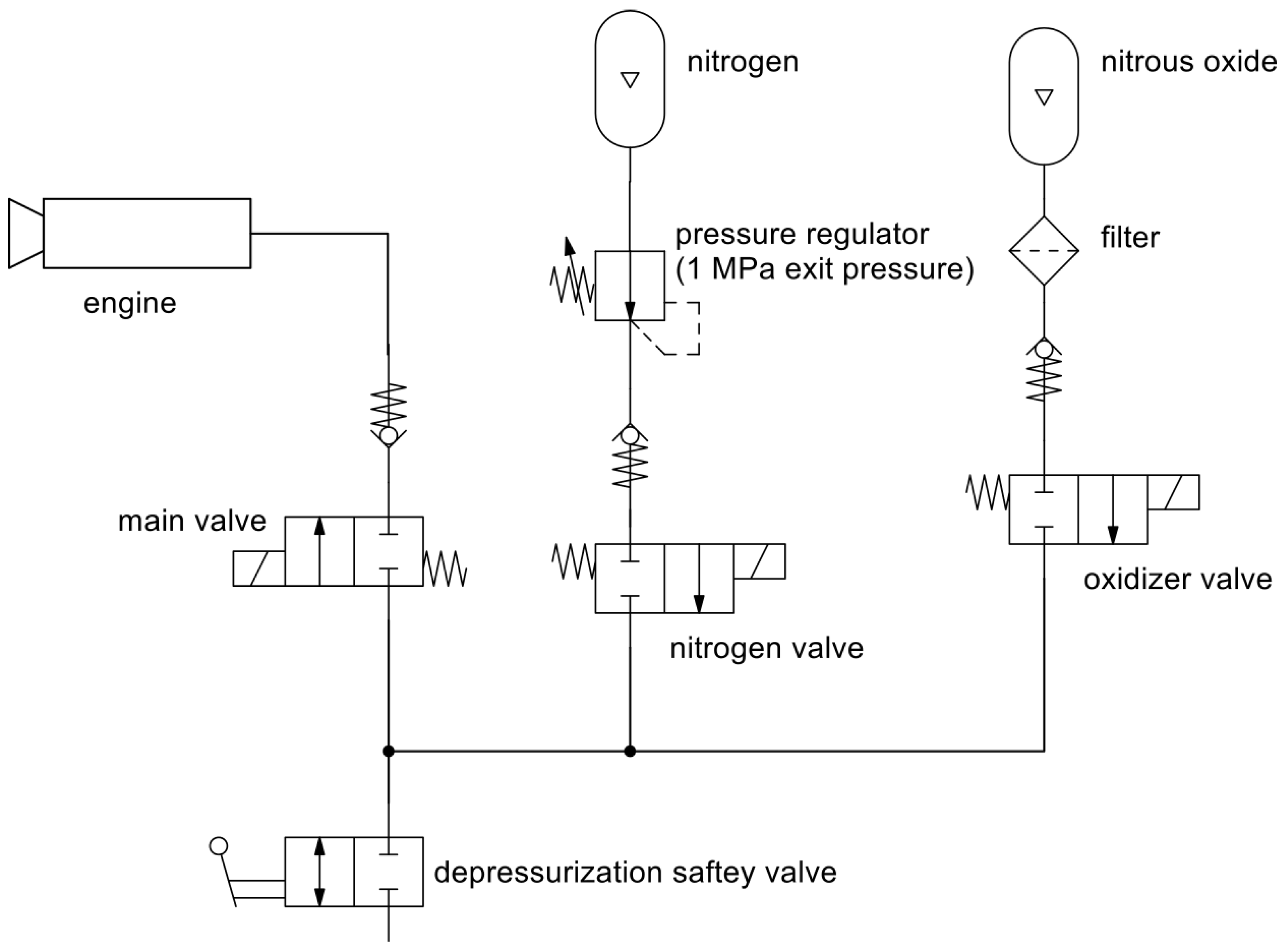
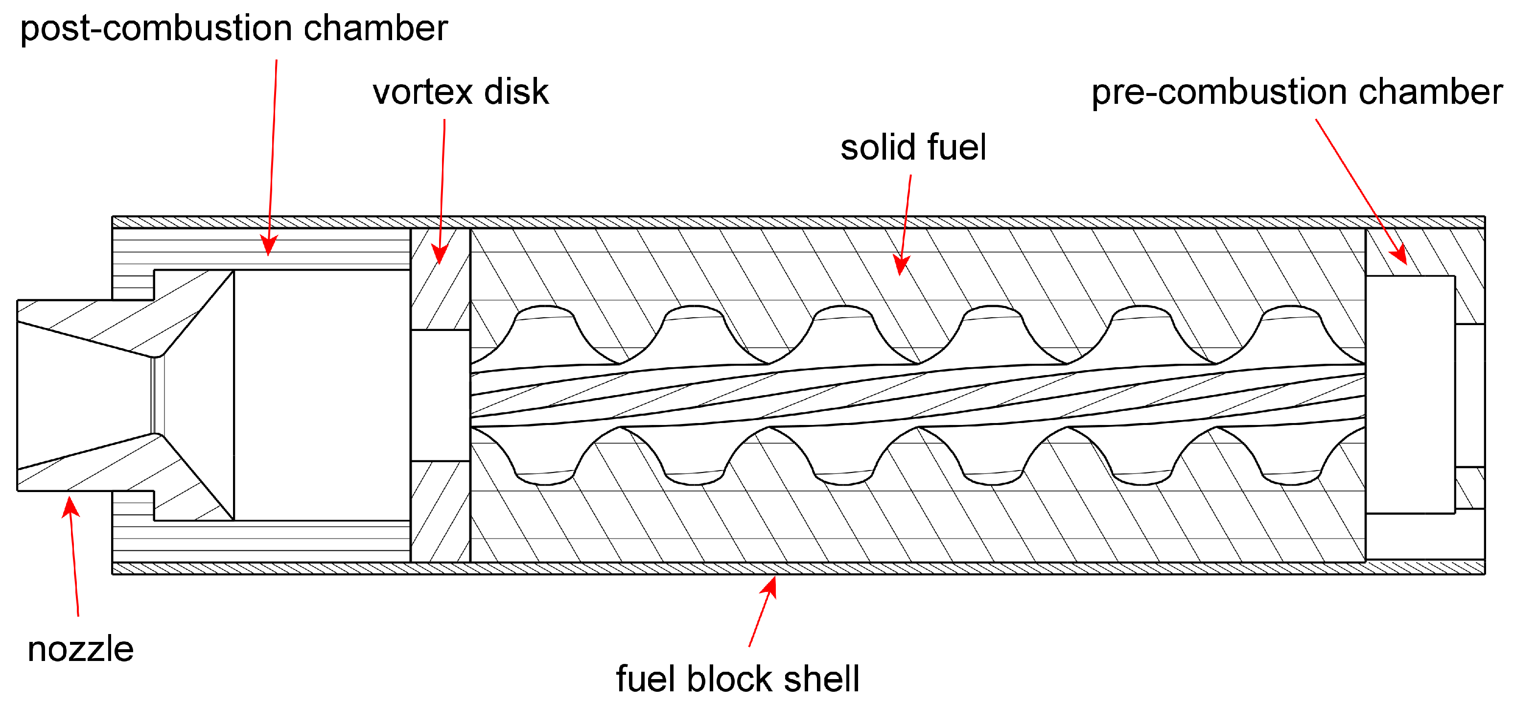
2.2.1. Overview of the Hybrid Rocket Engine

During the hybrid rocket engine design, attention was paid to easy handling and fast reusability during the test campaigns [15]. A cross section of the engine is shown in Figure 9. In order to perform many tests in a short period of time, the nozzle flange can be removed by a single person, allowing access to the fuel block. At the same time, a second person can replace the pre-heater, which is located at the rear of the engine. Detailed engine design parameters are presented in Table 4. The regression rate of 0.6 mm for Monoport and star was taken from previous works, while 1 mm was estimated for the twisted star [7].
An engine test consists of three phases. First, the pre-heater (a conventional solid rocket motor for model rockets) ignites and floods the combustion chamber with hot gases. This is followed by the oxidizer main valve opening, whereby the engine ignites (begin of phase two) due to the oxidizer decomposing exothermic in combination with the hot gases of the pre-heater. After ignition, a self-sustaining state develops. Through the exothermic reaction the top layer of HTPB becomes gaseous, feeding the reaction as fuel. In combination with the constant oxidizer flow through the injector a ongoing combustion is established, which consumes the solid fuel block from inside to outside. In order to describe the rate, in which the solid part is consumed by the reaction per second, the regression rate is used. At the end of the planned burn time (begin of phase three) the oxidizer is replaced by nitrogen gas to stop the reaction and freeze the existing geometry.

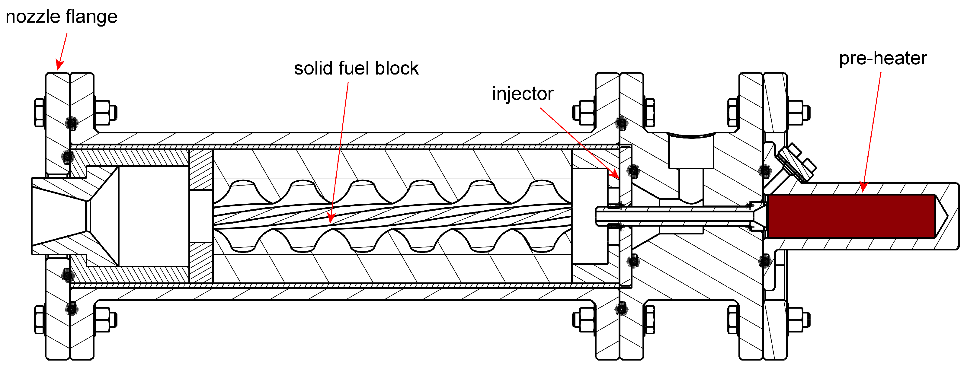
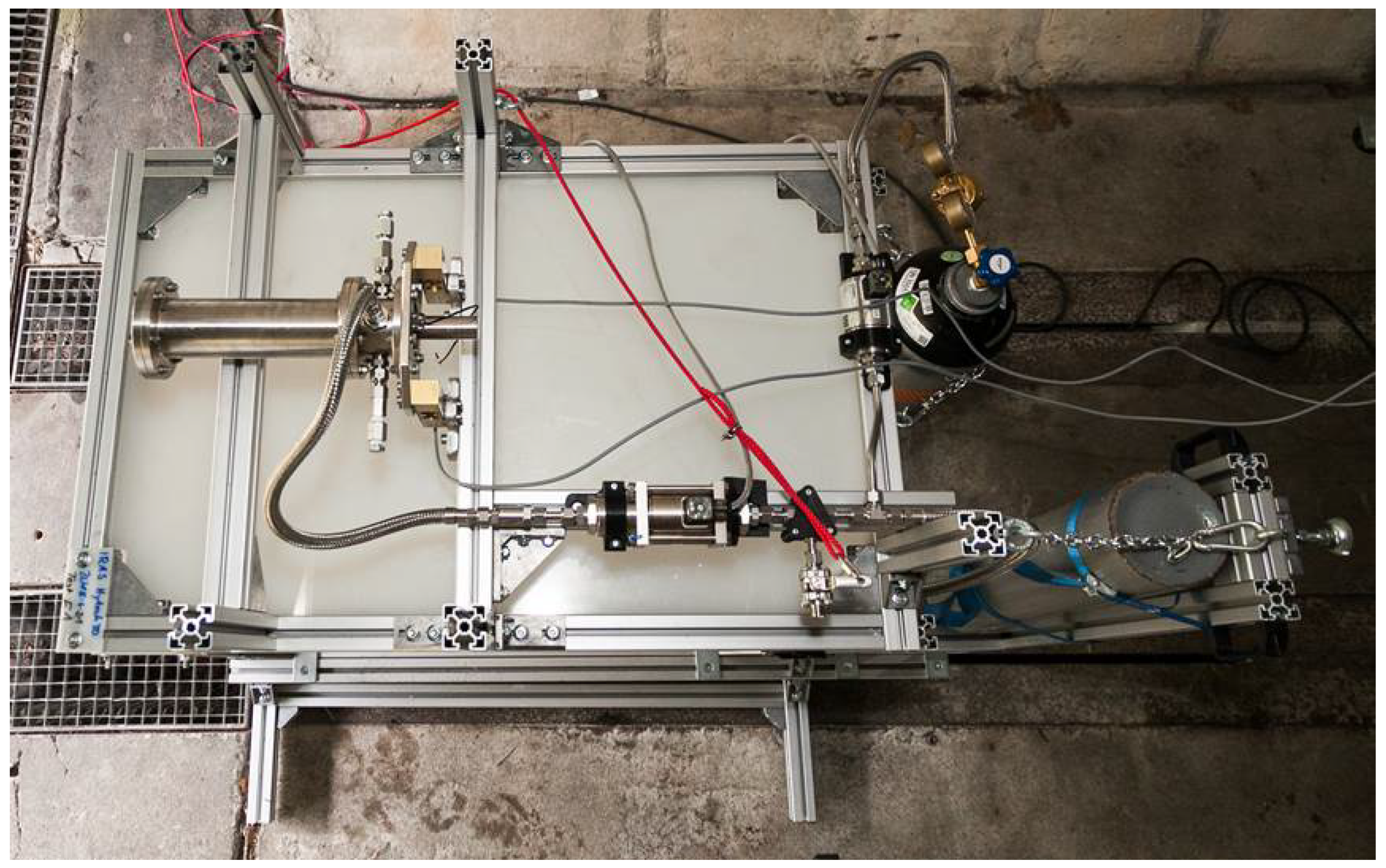
2.2.2. Overview of the Engine Test Bed

The test bed (Figure 10) was built to be a simple and transportable design. This was achieved through separating the test desk and the substructure, which is connecting the test bed to the ground and holds the gas cylinders. The fluid system, which is shown in Figure 11, consists of the oxidizer feeding, which can be switched to nitrogen via remote control. Due to the self-pressurizing characteristic [17] of N 2 O no additional pressure system is needed. Through a remotely controlled main valve the fluid is injected into the engine. As a safety feature a manual controlled valve can be opened with a long rope if all electronic system fail.

2.3. Test Plan and Process

The engine tests were conducted at the test facility of the DLR Trauen. To generate data at different stages, each of the three geometries were tested with a short, average and long burn duration.

3. Results and Discussion

3.1. Results

During the two campaigns, easy handling and refurbishment of the test bed was proven. The mean time between two tests could be reduced to under 30 min. Ignition was received every time directly except for one test, where the oxidizer valve was opened too late. The engine itself over performed during the first campaign in comparison to the thrust and mass flow calculations, which resulted in an after expansion outside of the nozzle with every geometry during all tests (Figure 12). This behavior can be explained by two factors. Firstly, the injector was designed with assumptions based on literature values. Later analysis revealed the oxidizer mass flow was too high. Secondly, the small size of the hybrid rocket engine resulted in high radiation and therefore, a higher regression rate. A higher regression rate of the solid fuel as a consequence of a higher radiation due to a smaller engine size is known [18,19], but was underestimated during design. Additionally, it was concluded that the regression rate was increased due to an erosion of a significant liquid layer. Due to the used pure, and therefore partly clear, HTPB, the radiation could heat deeper into the fuel block, creating a liquid layer that could be moved due to the flow momentum. In a second campaign, this issue was resolved through adding a small percentage ( 0.5 % ) of carbon black during the solid fuel block manufacturing process. This results in a higher radiation absorption on the fuel block surface [20] and therefore a thinner but hotter liquid layer. In the following, only a short overview over the test results is given. A more detailed analysis is conducted in the moment and should be published in the future.

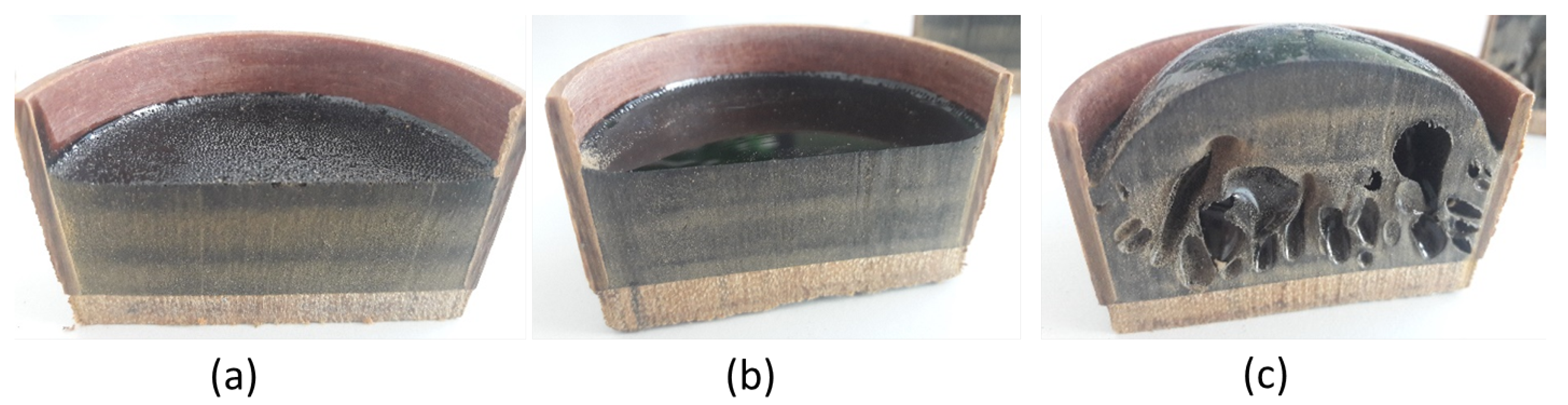
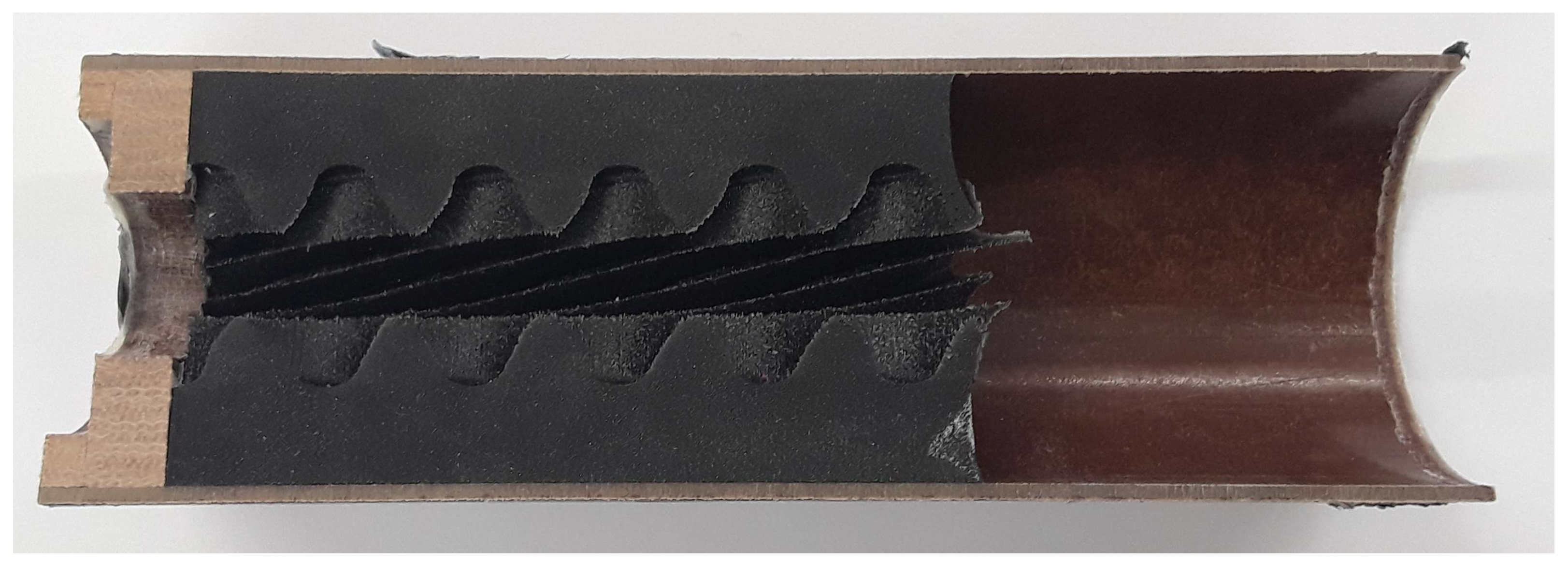
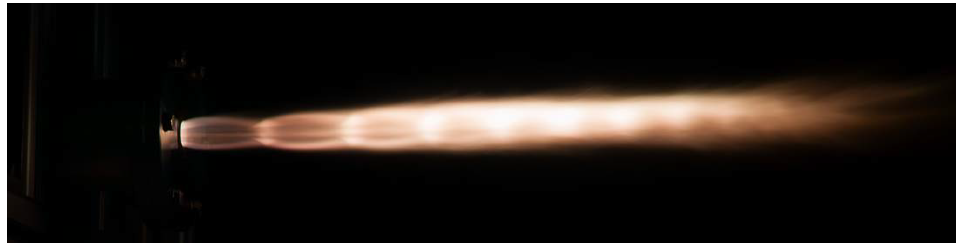
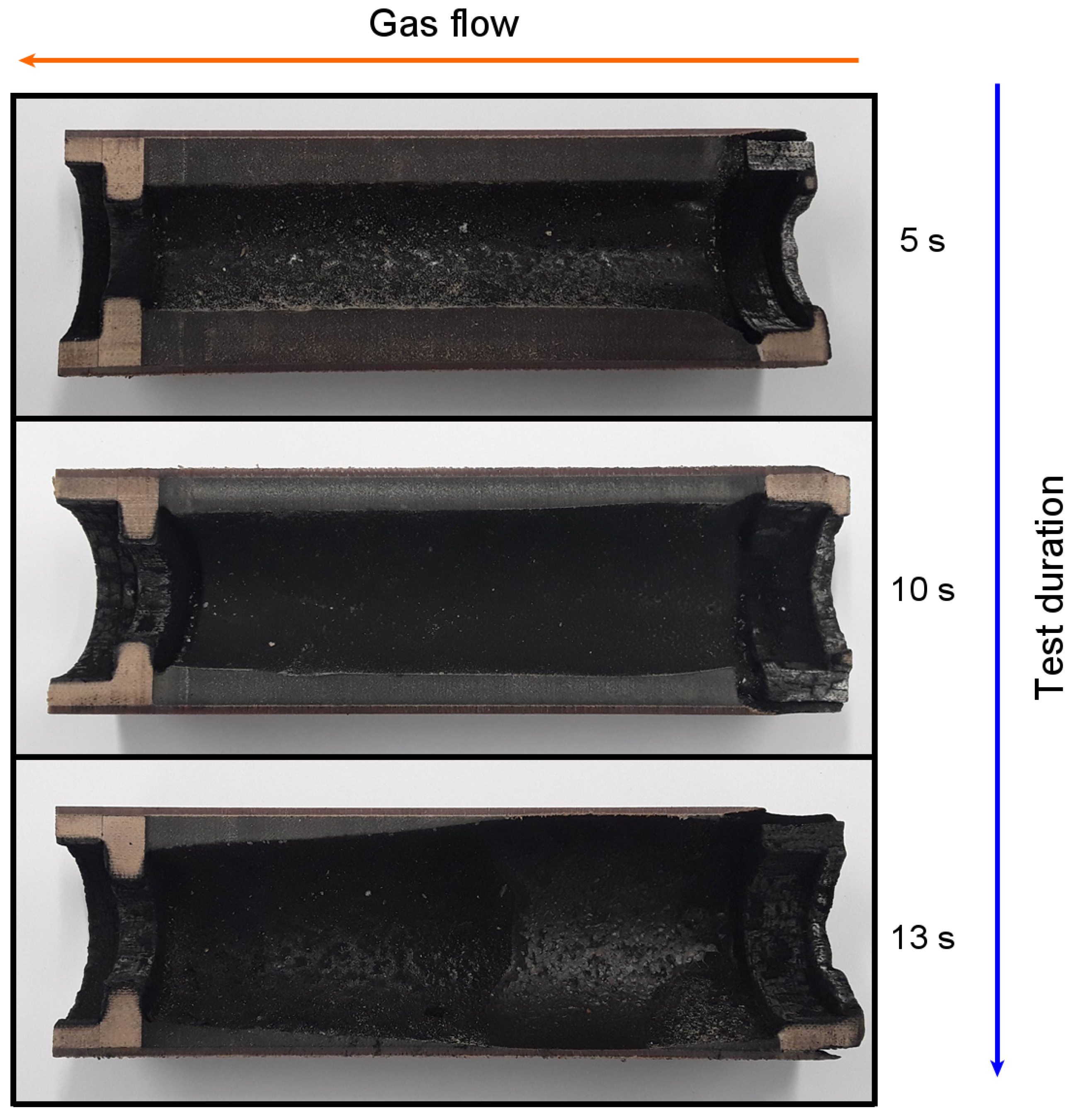
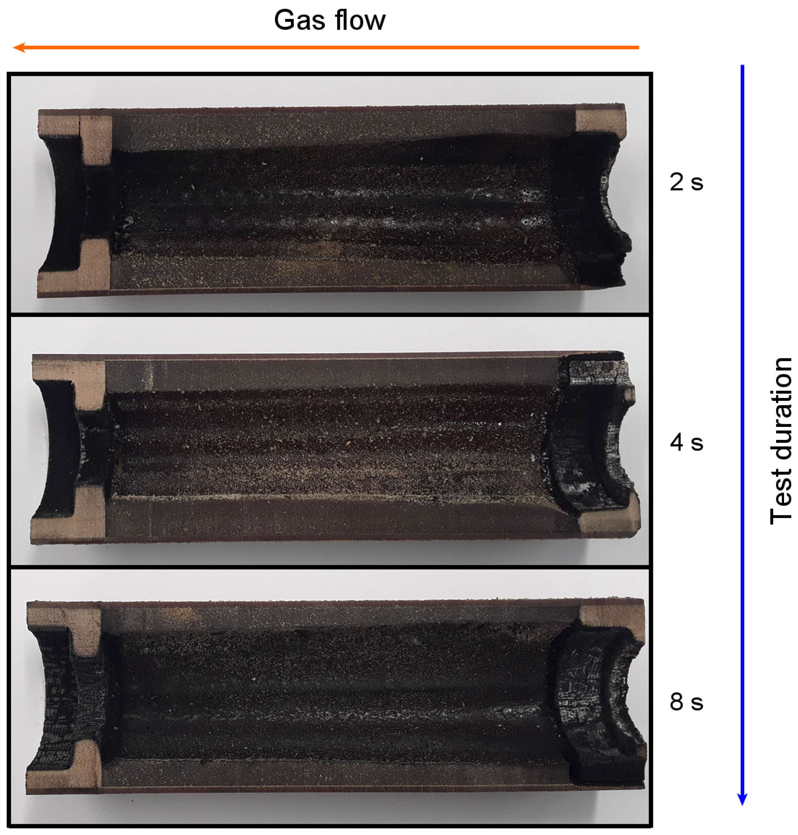
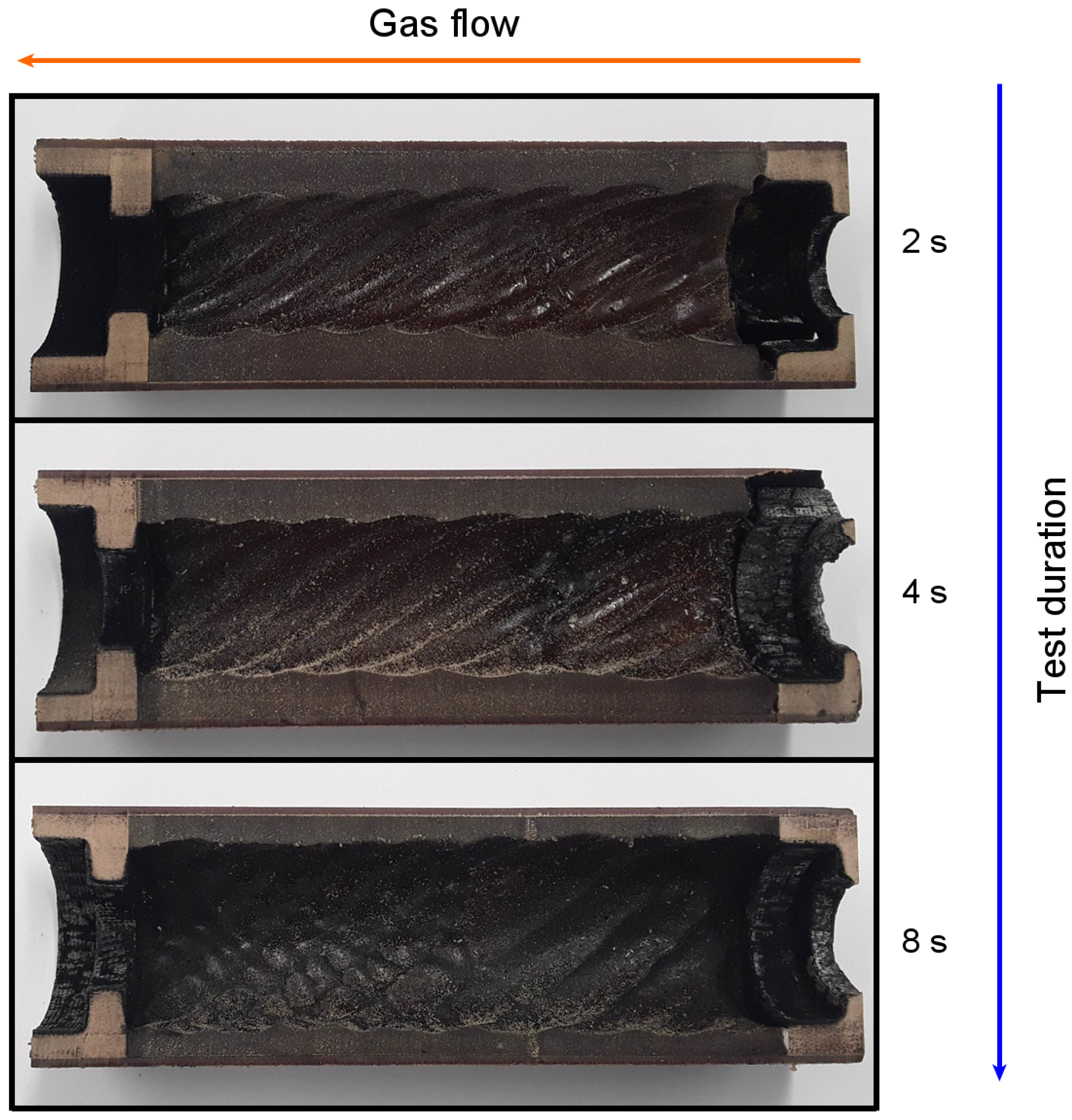
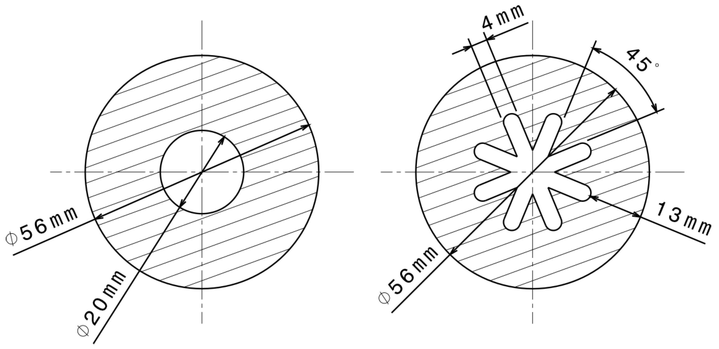
3.1.1. Geometrical Analysis

The Monoport showed a nominal and constant behavior over the length of the fuel block during the first 5 s. At longer burn durations, the regression rate near the injector was higher and consumed the most oxidizer. This resulted in a near stagnation of regression near the vortex disk. This can be seen in Figure 13.
The star geometry showed the same conical behavior in a decreased intensity with increasing test time. Additionally, the thin tips of the stars were very rapidly consumed by the exothermic reaction. The star pattern (groves along the flow direction) decreased with increased burn time. This can be seen in Figure 14, where nearly no star shape is left after 8 s.
The third geometry, the rotated star also displayed a depletion of the star pattern, but not as significant as the non-twisted star geometry. A conical effect (higher regression rate in the front than at the end probably due to the higher available oxidizer content) over the length of the fuel block nearly does not exist with the tested shape. This can be seen in Figure 15.

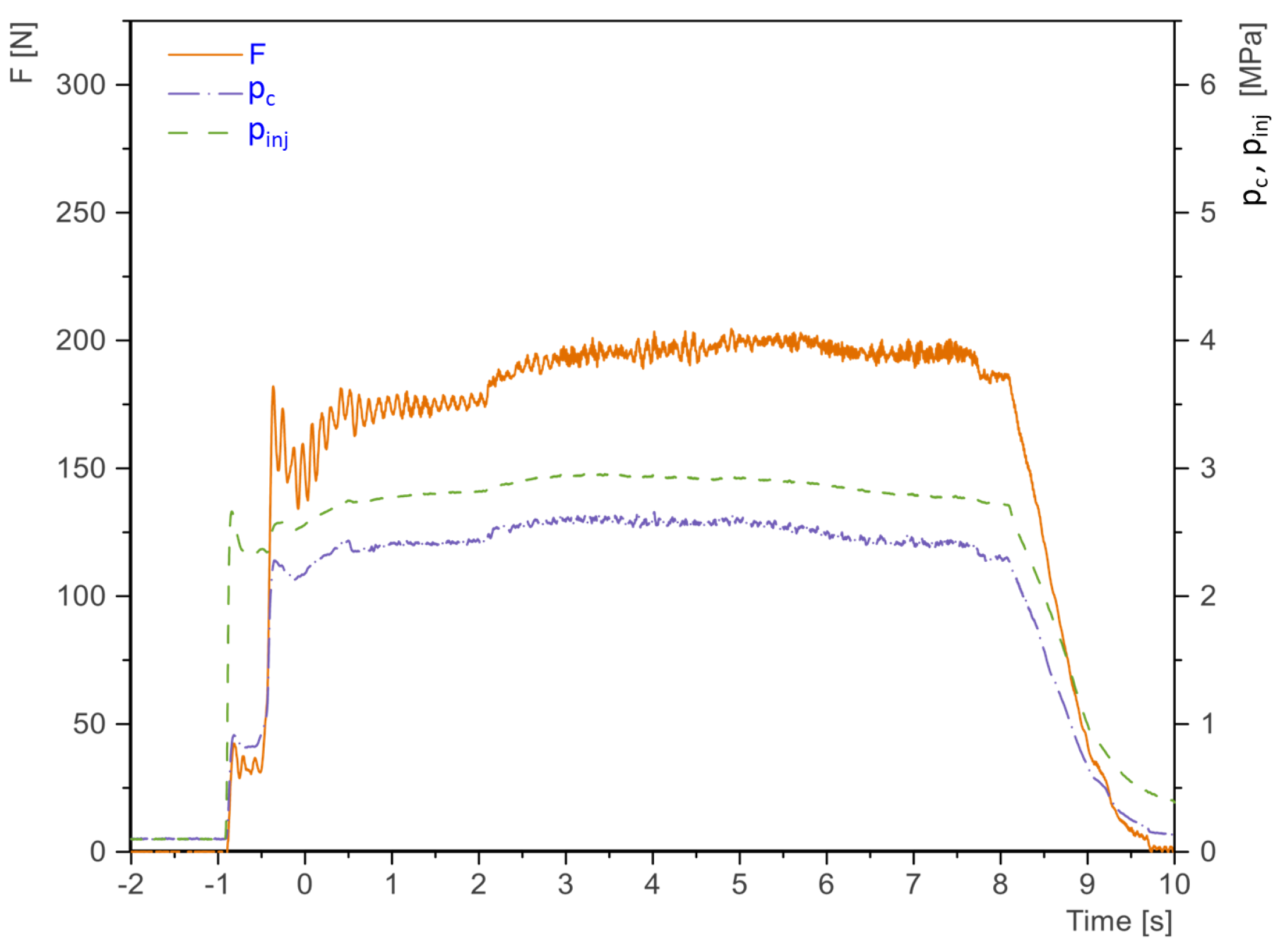
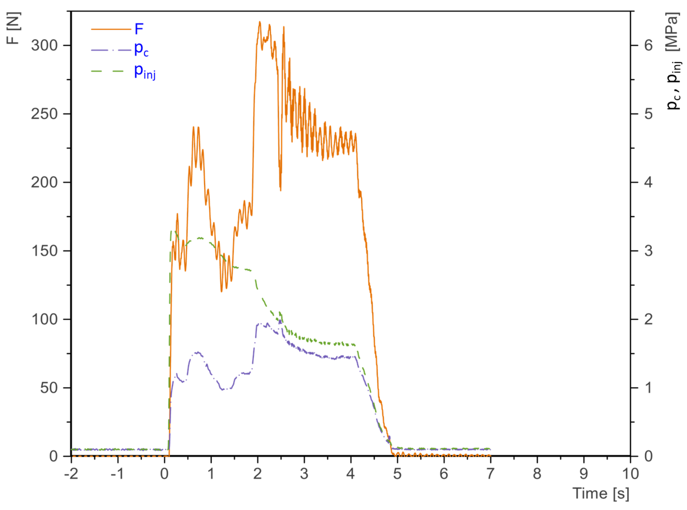
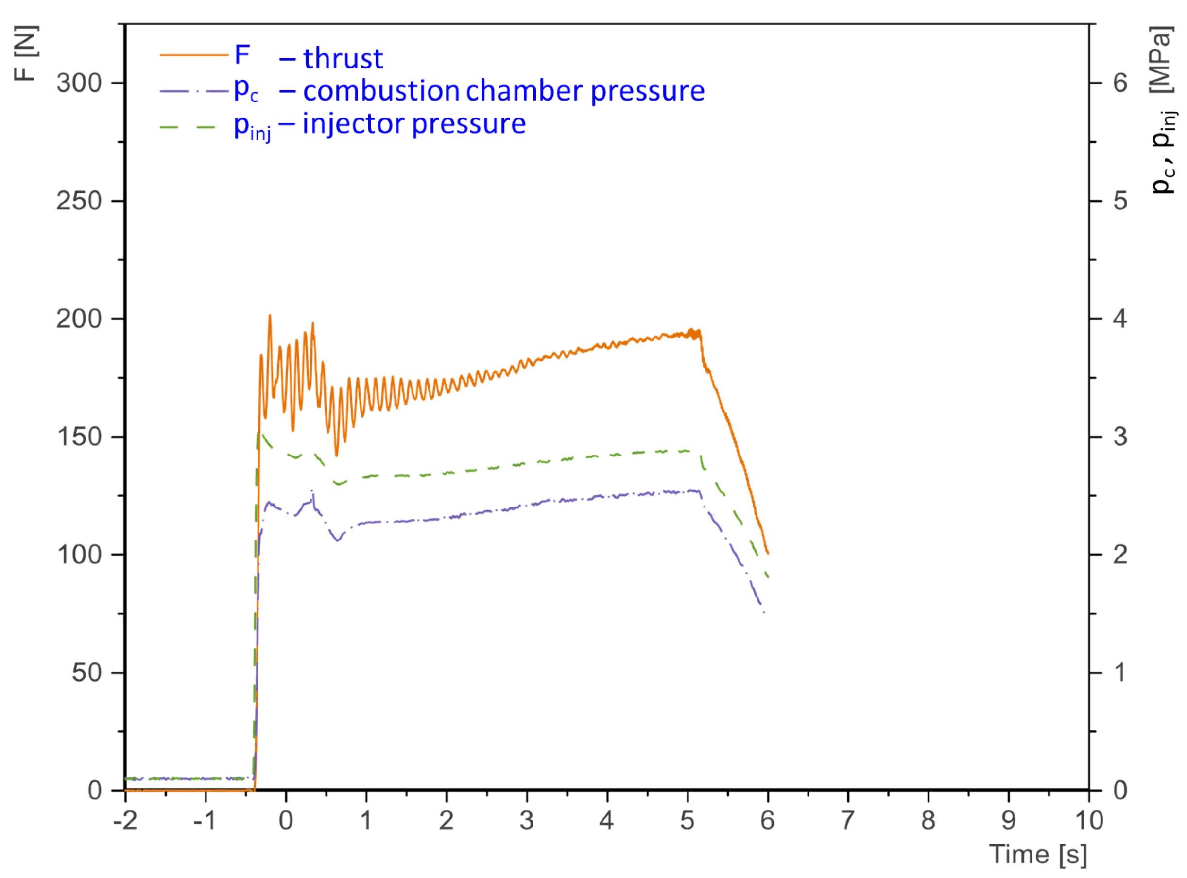
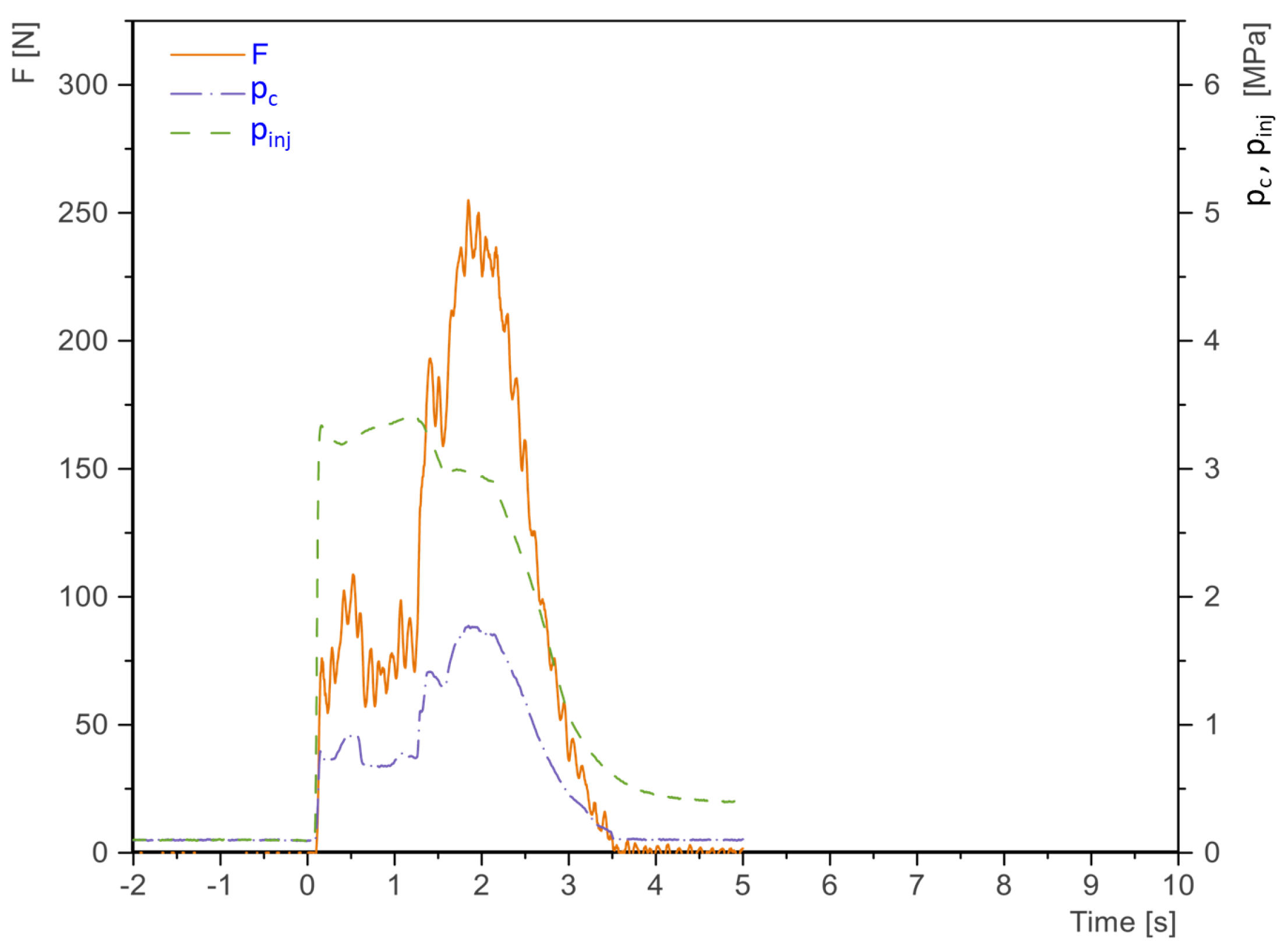
3.1.2. Data Analysis

To discuss the advantages and disadvantages of the rotation of the star geometry, test data are presented in the following. All engine tests had the problem of vibration with a frequency of around 9 Hz. The oscillation cannot be sensed in the pressure values and in the video sound of the tests; thus, it is expected that the oscillations were only mechanical in nature. In Figure 16 and Figure 17, engine test data of a star geometry are shown. In contrast, Figure 18 and Figure 19 present the data of a rotated star. As expected, the peak thrust increased significantly due to the higher regression rate r ˙ and the higher mass flow of fuel and oxidizer. Based on the mass differences of the fuel and burn time, the increase of the regression rate is estimated to be about 1.5 times higher. As the tests were only meant to demonstrate the complete production of 3D-printed mold geometries, no sophisticated measurement system for the regression rate was used. Further tests and adaptations are necessary to obtain valid data for the regression rate. As a disadvantage of the rotated geometry has to be noticed that a longer ignition phase can be seen. The time for thrust build-up increased from 0.5 to about 1.75 s. It is expected that the star standouts shadowed (covered) the downstream surface due to the rotation. Thus, the ignition system was undersized for the increased task.

4. Conclusions and Outlook

In this study, it was shown that it is possible to print dissolving molds that enable the production of complex flow-optimized shapes. These geometries allow an increase in the regression rate of solid fuel in hybrid rocket engines, thus enabling them to compensate partly for a major disadvantage; however, further tests are necessary to evaluate this in depths. The presented methods for designing and manufacturing such molds were sufficient to produce different HTPB fuel blocks. Test within the project have shown that this process is easily scalable, which enables the production of complex molds that are larger than the 3D printer. The solid fuel blocks performed well with the addition of carbon black in the newly built hybrid rocket engine according to peak thrust values. The ignition and combustion were stable, but in case of the rotated star geometry ignition took longer. It was shown that the rotated star geometry resulted in a more even regression behavior over the fuel block length combined with a higher peak thrust—this is due to the proposed increased regression rates through the geometry rotation. Due to the detected vibrations in the test data, a mechanical stiffening and damping of the test bed has to be considered.
The examined approaches can be used in the future to develop new generations of hybrid engines with high thrust or cast solid rocket motors with complex fuel geometries thus enabling new thrust profiles.

Author Contributions

Conceptualization, B.G. and S.L.; Project administration, E.S.; Software, B.G.; Supervision, S.L.; Validation, J.B.; Visualization, B.G.; Writing—original draft, B.G.; Writing—review & editing, J.B. and E.S. All authors have read and agreed to the published version of the manuscript.

Funding

This research was funded by the NBank in the project HyTech3D (grant number ZW 3-85006949).

Data Availability Statement

No new data except the one presented within this paper was created.

Acknowledgments

We thank the NBank for funding the project HyTech3D. Special thanks to DLR Trauen and especially Jürgen Veth for enabling the engine tests. We acknowledge support by the German Research Foundation and the Open Access Publication Funds of Technische Universität Braunschweig.

Conflicts of Interest

The authors declare no conflict of interest. The funders had no role in the design of the study; in the collection, analyses, or interpretation of data; in the writing of the manuscript, or in the decision to publish the results.

Abbreviations

The following abbreviations are used in this manuscript:
ASInstitute of Aerodynamics and Flow Technology
CACyanoacrylate adhesive
CADComputer aided design
DBTDLDibutylzinn-dilaurat
DLRGerman Aerospace Center
FDMFused Deposition Modeling
HTPBHydroxyl-terminated polybutadiene
IPDIIsophorone diisocyanate
IRASInstitute of Space Systems
ISPspecific impulse
N 2 ONitrous oxide
PVAPolyvinyl alcohol

Appendix A

Figure A1. The flow chart of the mold design process.
Aerospace 08 00220 g0a1

References

  1. Božić, O.; Porrmann, D.; Lancelle, D.; Hartwig, A. Program AHRES and its contribution to assess features and current limitations of hybrid rocket propulsion. In Proceedings of the 63th Congress of International Astronautical Federation, IAC-12-C4, Naples, Italy, 1–5 October 2012. [Google Scholar]
  2. Kumar, M.; Joshi, P. Regression Rate Study of Cylindrical Stepped Fuel Grain of Hybrid Rocket. Mater. Today 2017, 4, 8208–8218. [Google Scholar] [CrossRef]
  3. Nagata, H.; Ito, M.; Maeda, T.; Watanabe, M.; Uematsu, T.; Totani, T.; Kuo, I. Development of CAMUI hybrid rocket to create a market for smallrocket experiments. Acta Astronaut. 2006, 59, 253–258. [Google Scholar] [CrossRef] [Green Version]
  4. Tian, H.; Duan, Y.; Zhu, H. Three-dimensional numerical analysis on combustion performance and flow of hybrid rocket motor with multi-segmented grain. Chin. J. Aeronaut. 2020, 33, 1181–1191. [Google Scholar] [CrossRef]
  5. Tian, H.; He, L.; Zhu, H.; Wang, P.; Xu, X. Numerical and experimental investigation on hybrid rocket motor with two-hole segmented rotation grain. Aerosp. Sci. Technol. 2019, 92, 820–830. [Google Scholar] [CrossRef]
  6. Lee, C.; Na, Y.; Lee, J.; Byun, Y. Effect of induced swirl flow on regression rate of hybrid rocket fuel by helical grain configuration. Aerosp. Sci. Technol. 2007, 11, 68–76. [Google Scholar] [CrossRef]
  7. Klaus, J.T.; Božić, O.; May, S.; Poppe, G. Erhöhung des Schubs von Hybridraketentriebwerken durch Optimierung der Brennstofftreibsatzform mit verwundener Finozylgeometrie. In Proceedings of the 65. DLRK Congress, Braunschweig, Germany, 15–16 September 2016. [Google Scholar]
  8. Tian, H.; Li, Y.; Li, C.; Sun, X. Regression rate characteristics of hybrid rocket motor with helical grain. Aerosp. Sci. Technol. 2017, 68, 90–103. [Google Scholar] [CrossRef]
  9. Wang, Z.; Lin, X.; Li, F.; Yu, X. Combustion performance of a novel hybrid rocket fuel grain with a nested helical structure. Aerosp. Sci. Technol. 2020, 97, 105613. [Google Scholar] [CrossRef]
  10. May, S.; Poppe, G.; Pöppelmann, M.; Sültrop, H.P.; Vörsmann, P. Development of a supersonic research rocket with hybrid rocket engine. In Proceedings of the European Conference for AeroSpace Sciences, Munich, Germany, 1–5 July 2013. [Google Scholar]
  11. Arves, J.; Jones, H.; Kline, K.; Smith, K.; Slack, T.; Bales, T. Development of a N2O/HTPB hybrid rocket motor. In Proceedings of the 33rd Joint Propulsion Conference and Exhibit, Seattle, WA, USA, 6–9 July 1997. [Google Scholar]
  12. Guirguis, O.W.; Moselhey, M.T.H. Thermal and Structural Studies of Poly (Vinyl Alcohol) and Hydroxypropyl Cellulose Blends. Nat. Sci. 2020, 4, 57–67. [Google Scholar] [CrossRef] [Green Version]
  13. Bina, C.K.; Kannan, K.; Ninan, K. DSC study on the effect of isocyanates and catalysts on the HTPB cure reaction. J. Therm. Anal. Calorim. 2004, 78, 753–760. [Google Scholar] [CrossRef]
  14. Bhowmik, D.; Sadavarte, V.S.; Pande, S.M.; Saraswat, B.S. An energetic binder for the formulation of advanced solid rocket propellants. Central European Journal of Energetic Materials. J. Energ. Mater. 2015, 12, 145–158. [Google Scholar]
  15. Grefen, B. Design of a Hybrid Rocket Motor for the Testing of Innovative Additive Manufactured Propellant Blocks with Flow Optimized Inner Geometry. Bachelor’s Thesis, IRAS, TU Braunschweig, Braunschweig, Germany, 2017. [Google Scholar]
  16. Buchner, C. Analysis of the Burn-Off Behavior of Different Hybrid Rocket Engine Propellant Block Geometries. Bachelor’s Thesis, IRAS, TU Braunschweig, Braunschweig, Germany, 2018. [Google Scholar]
  17. Berger, B. Is Nitrous Oxide Safe? 2007. Available online: http://www.spl.ch (accessed on 12 July 2021).
  18. Ben-Arosh, R.; Gany, A. Similarity and Scale Effects in Solid-Fuel Ramjet Combustors. J. Propuls. Power 1992, 8, 615–623. [Google Scholar] [CrossRef]
  19. Cai, G.; Zeng, P.; Li, X.; Tian, H.; Yu, N. Scale effect of fuel regression rate in hybrid rocket motor. Aerosp. Sci. Technol. 2013, 24, 141–146. [Google Scholar] [CrossRef]
  20. Carmaicino, C.; Scaramuzzino, F.; Russo Sorge, A. Trade-off between paraffin-based and aluminium-loaded HTPB fuels to improve performance of hybrid rocket fed with N2O. Aerosp. Sci. Technol. 2014, 37, 81–92. [Google Scholar] [CrossRef]
Figure 1. Overview over the different fuel block geometries: (a) Monoport; (b) Star; (c) rotated Star [15].
Aerospace 08 00220 g001
Figure 2. Detailed view of the cross sections of the Monoport (left) and the Star (right). Rotated Star and Star share the same cross section.
Aerospace 08 00220 g002
Figure 3. Sectional view of the two mold parts and gluing area.
Aerospace 08 00220 g003
Figure 4. Top view of a printed rotated star geometry.
Aerospace 08 00220 g004
Figure 5. The two moldings are glued together (white-yellowish) and onto the vortex disk (dark brown) [16].
Aerospace 08 00220 g005
Figure 6. Sectional view of the solid fuel block.
Aerospace 08 00220 g006
Figure 7. Sectional view of different compositions of HTPB, IPDI and DBTL. All mixtures were performed with the same new type of HTPB and constant amount of carbon black: (a) mixture with 7.66 % IPDI; (b) mixture with 9.58 % IPDI; (c) mixture with 11.50 % IPDI. Pictures: F. Heeg, IRAS, TU Braunschweig.
Aerospace 08 00220 g007
Figure 8. Sectional view of a test fuel block after the mold was dissolved.
Aerospace 08 00220 g008
Figure 9. Sectional view of the hybrid rocket engine.
Aerospace 08 00220 g009
Figure 10. Overview of the engine test bed.
Aerospace 08 00220 g010
Figure 11. The fluid system of the engine test bed with the separated nitrogen and nitrous oxide feeding systems.
Aerospace 08 00220 g011
Figure 12. Side view of the jet blast with under expansion form a Monoport geometry.
Aerospace 08 00220 g012
Figure 13. Sectional view of the Monoport fuel blocks after different test times.
Aerospace 08 00220 g013
Figure 14. Sectional view of the star fuel blocks after the three different test times.
Aerospace 08 00220 g014
Figure 15. Sectional view of the rotated star fuel blocks after different test times.
Aerospace 08 00220 g015
Figure 16. Test data of an engine test with a burn time of 5 s and star geometry.
Aerospace 08 00220 g016
Figure 17. Test data with 8 s burn time and star geometry.
Aerospace 08 00220 g017
Figure 18. Data of an engine test of the rotated star shape with 2 s of burn time.
Aerospace 08 00220 g018
Figure 19. Test data of a rotated star geometry with 4 s burn time.
Aerospace 08 00220 g019
Table 1. Overview over the design aspects and their effects.
AspectsEffects on Design
structural integritywall thickness required to retain mold shape after casting (hydrostatic pressure)
leak-proofsingle layers can have defects through the characteristics of fused deposition modeling (FDM) printing, multipath structure in combination with high viscosity of hydroxyl-terminated polybutadiene (HTPB) results in leak-proof mold
dissolving speedthin walls, flow channel for water, large surface
economic material usagethin walls, solid parts with low percentage of infill
print timethin walls, solid parts with low percentage of infill
scalabilitygluing needed when mold larger than printer
gluinggluing surfaces and centering structure needed, for minimal material usage should be printed with overhang
overhangstructure for FDM printing in the air without the need of support structure
Table 2. Overview over the resulting design and printing parameters.
ParameterValue
overhang angle 20 against FDM printer Z-axis
wall thickness1.3 mm
layer height0.2 mm
nozzle temperature210 °C
print bed temperature70 °C
infill 40 %
enable retractionfalse
print speed40 mm/s
first layer speed20 mm/s
travel speed120 mm/s
print time for completed moldaround 8 h
Table 3. Overview over the composition for casting.
ComponentCampaign 1Campaign 2
HTPB 92.08 % 90.16 %
Isophorone diisocyanate (IPDI) 7.66 % 9.58 %
Dibutylzinn-dilaurat (DBTL) 0.02 % 0.02 %
carbon black- 0.5 %
Table 4. Overview of the engine design parameters [15].
ParameterMonoportStarRotated Star
oxidizer-fuel ratio666
chamber pressure [MPa]222
average fuel mass flow [g/s] 10.2 12.9 22.4
average oxidizer mass flow [g/s] 61.2 77.3 134.5
burn time [s] 30.00 21.67 13.00
average Thrust [N]131165288
maximum Thrust [N]140170295
point of maximum Thrust [s]3000
Publisher’s Note: MDPI stays neutral with regard to jurisdictional claims in published maps and institutional affiliations.

