
A Parametric Study on the Aeroelasticity of Flared Hinge Folding Wingtips


Abstract
:1. Introduction
2. Modelling
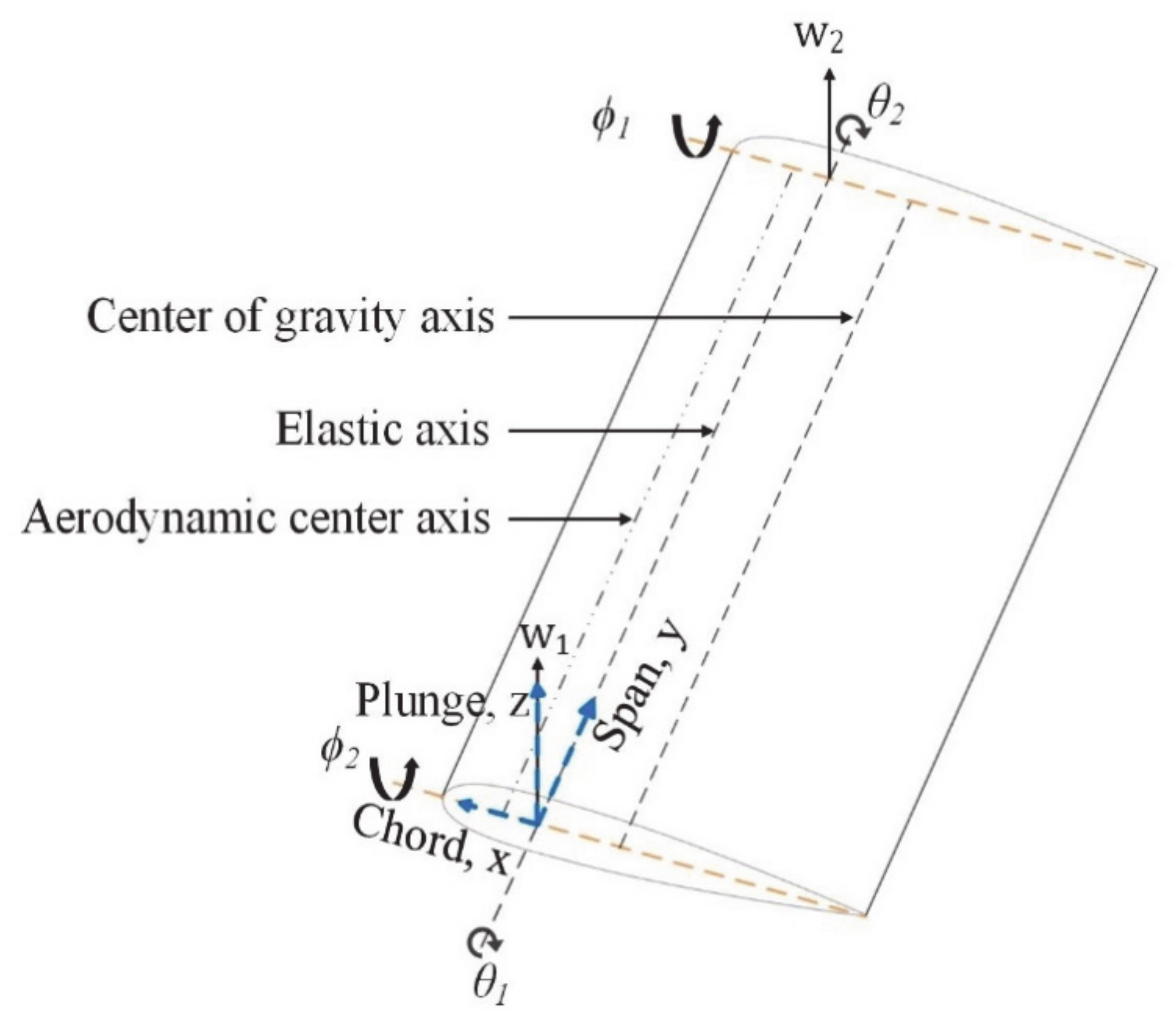
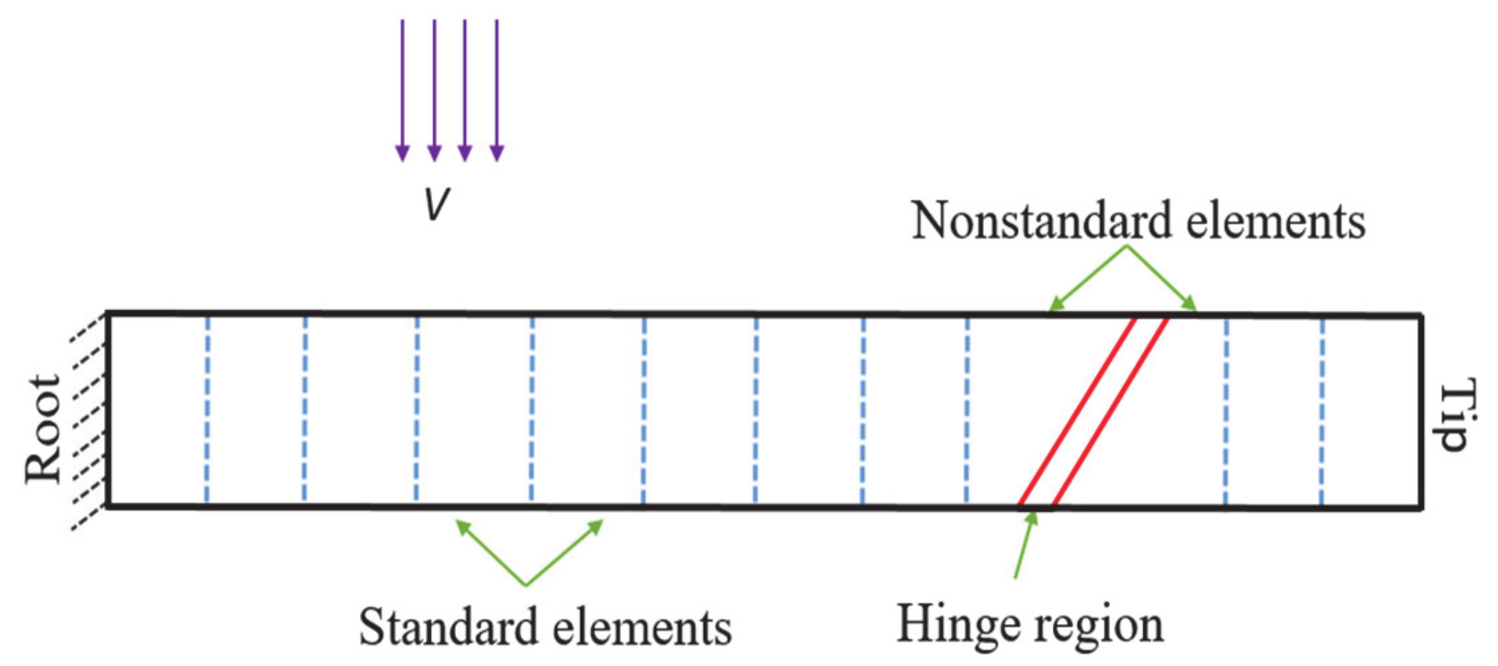
2.1. Structural Dynamics Solver
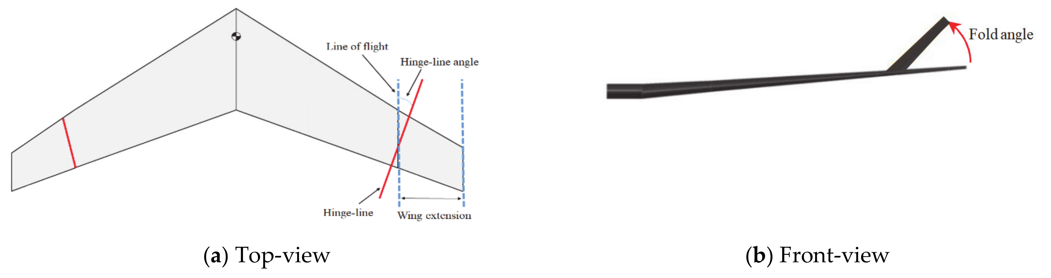
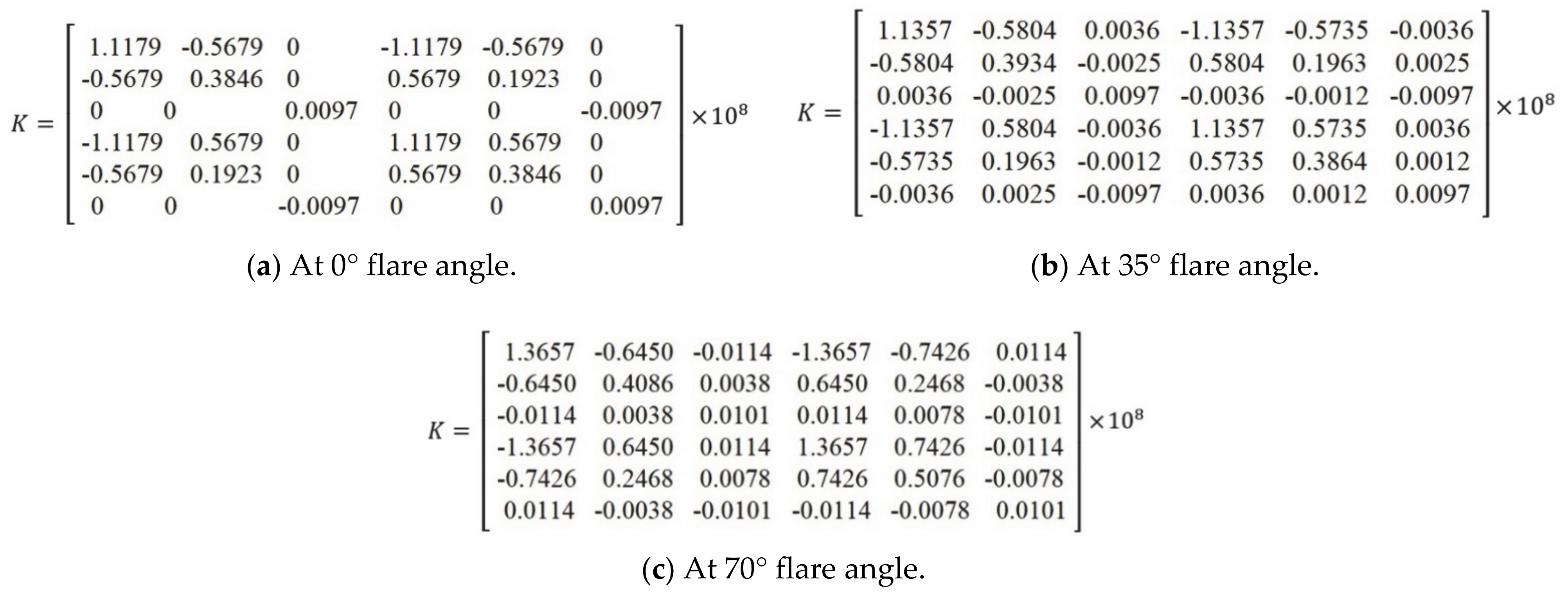
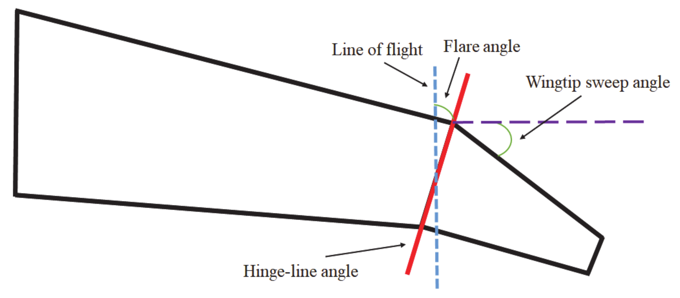
2.2. Modelling the Flared Hinge
2.3. Aerodynamic Solver
2.4. Aeroelastic System
2.5. Validation
3. Parametric Study: Linear Aeroelasticity
3.1. Folding the Baseline Wing
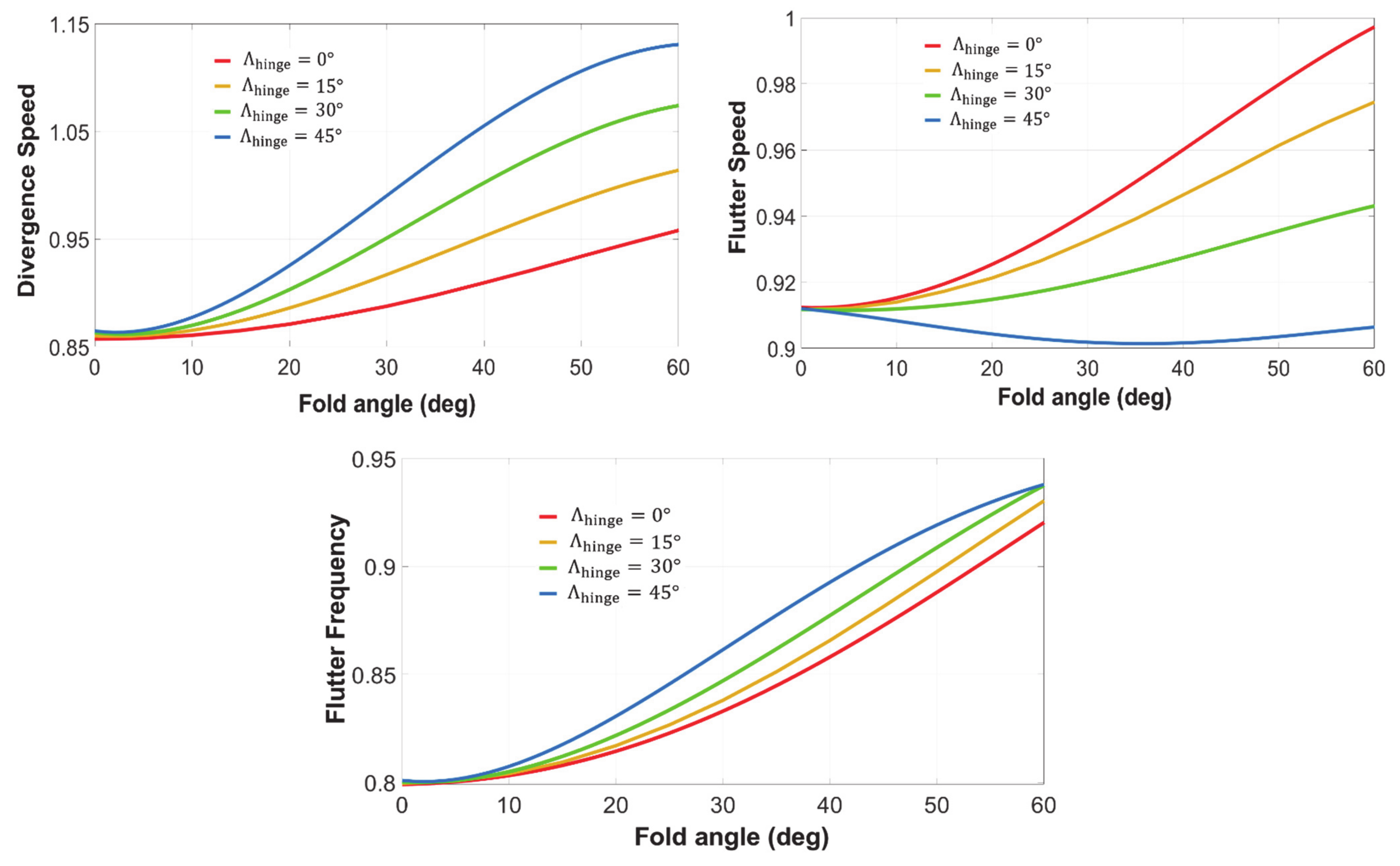
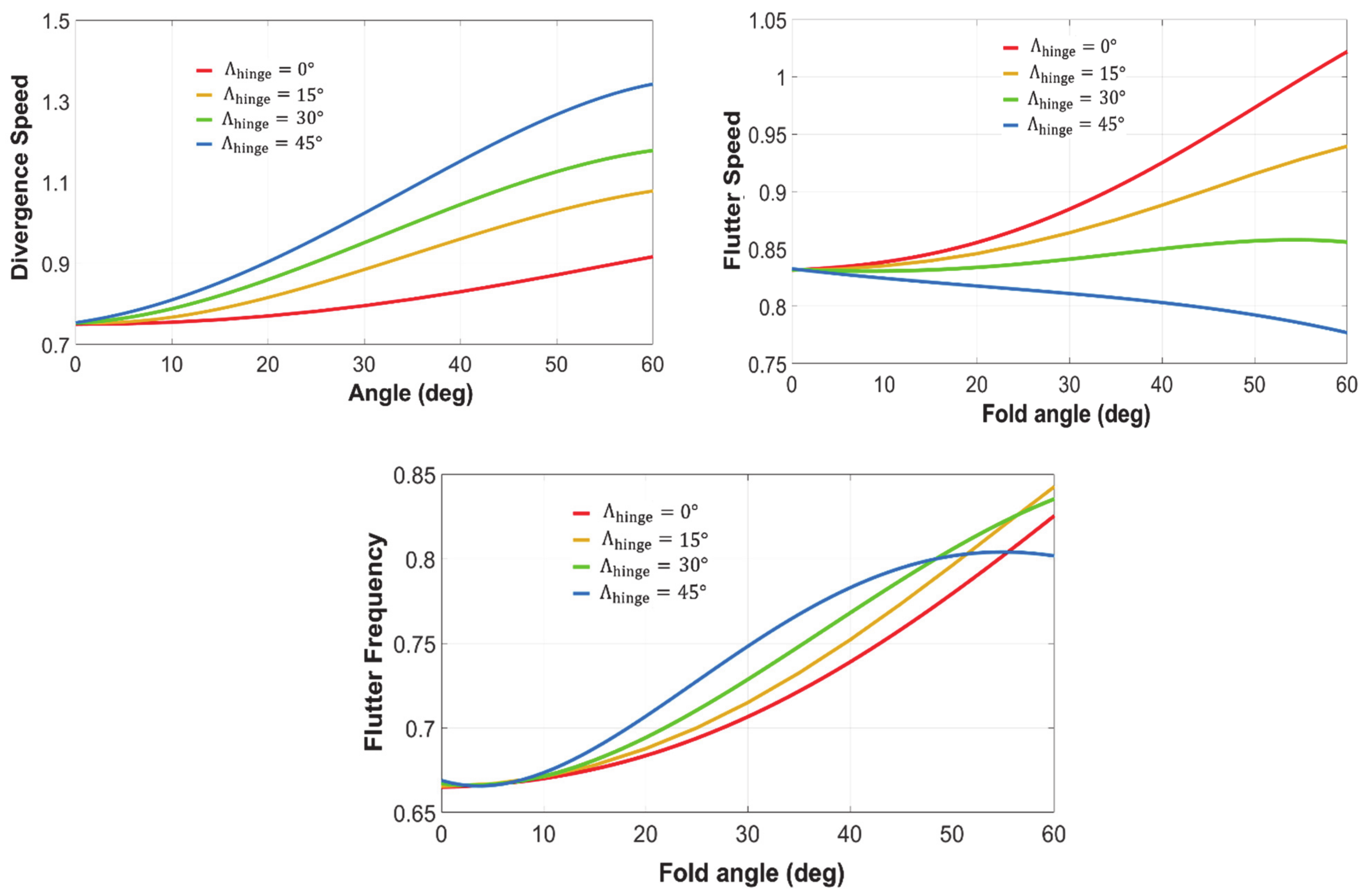
3.1.1. Flare Angle
3.1.2. Quasi-Steady Response to Discrete Gusts
3.1.3. Hinge Stiffness
3.2. Adding Folding Wingtip
3.2.1. Wingtip Size
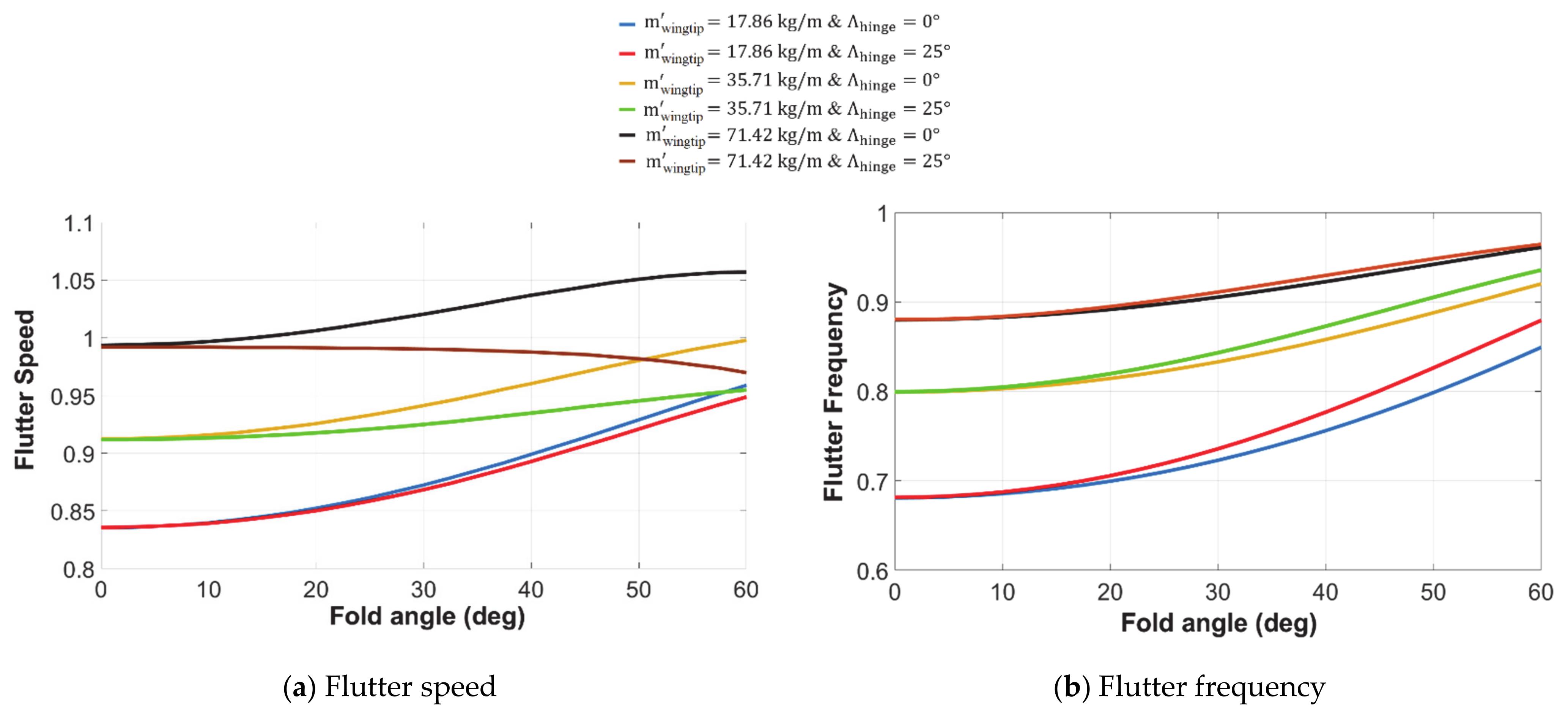
3.2.2. Wingtip Mass
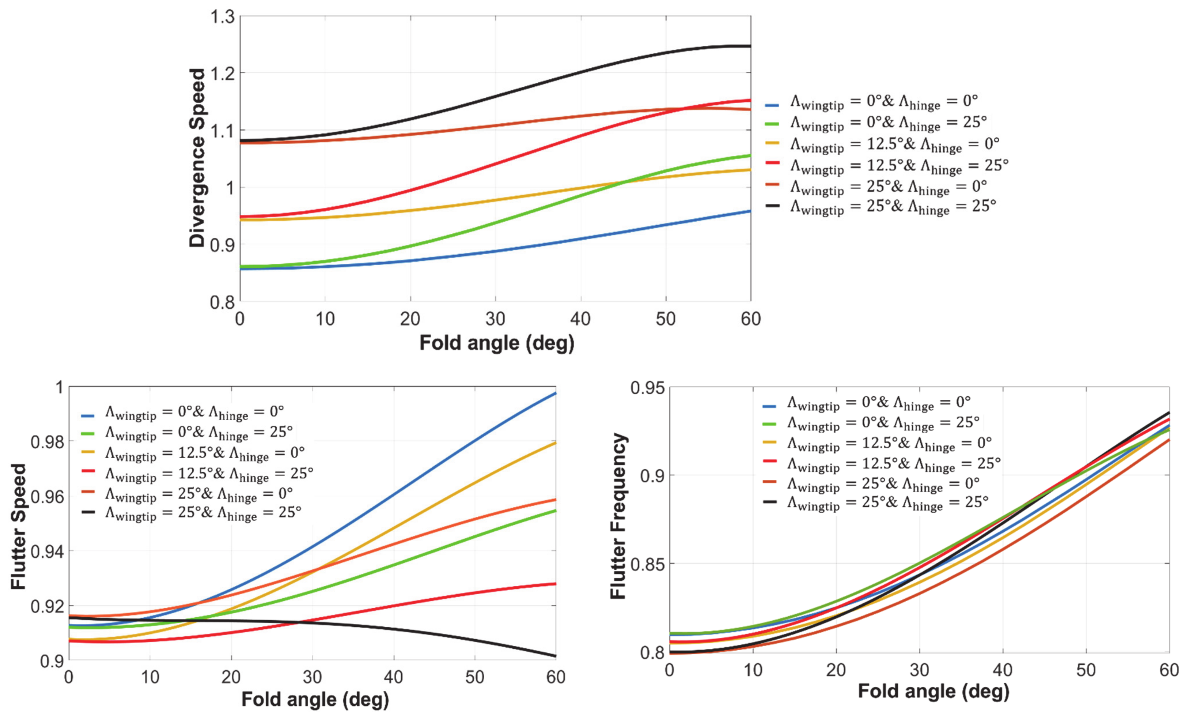
3.2.3. Wingtip Sweep
4. Nonlinear Aeroelasticity
4.1. Nonlinear Hinge
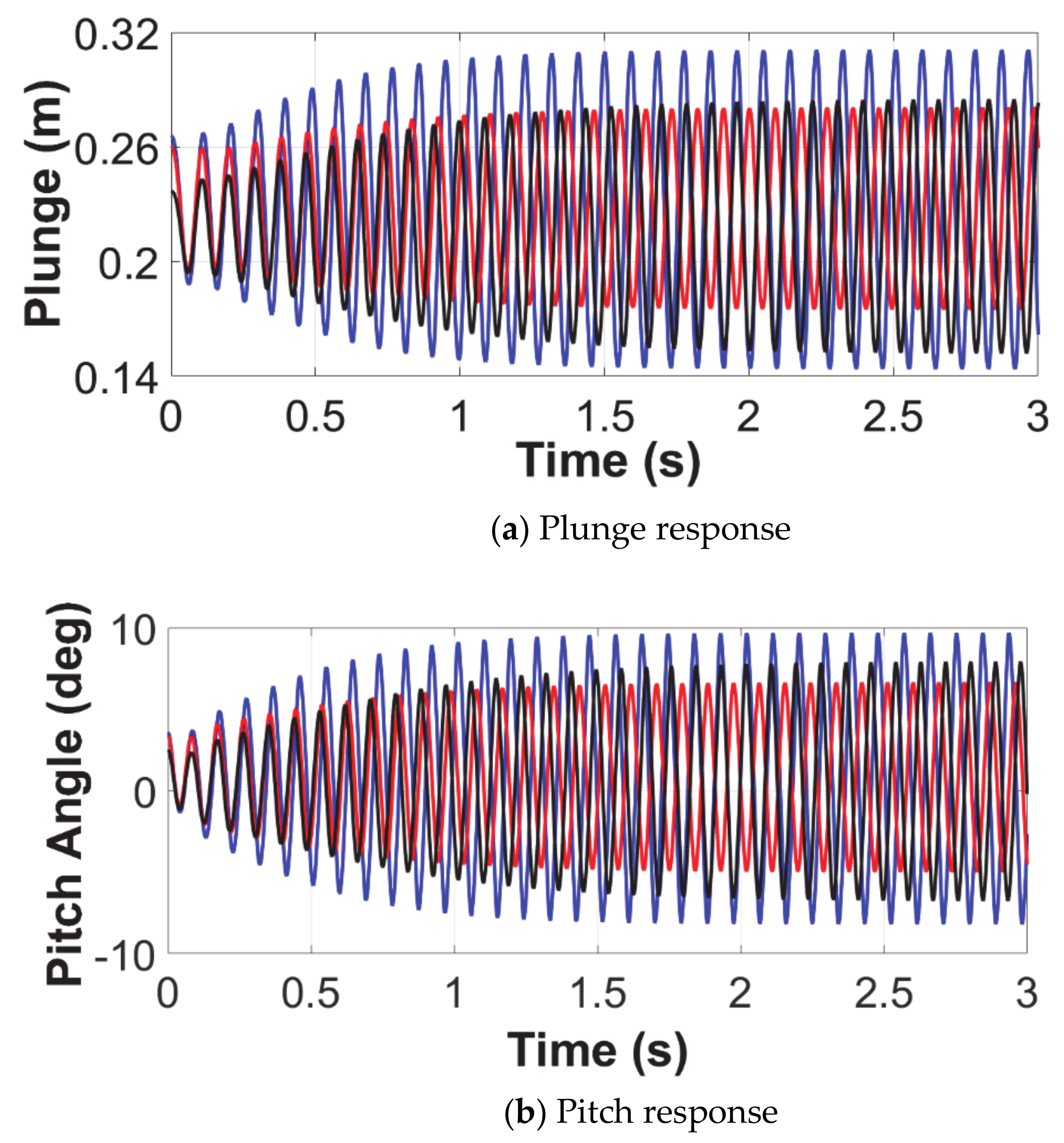
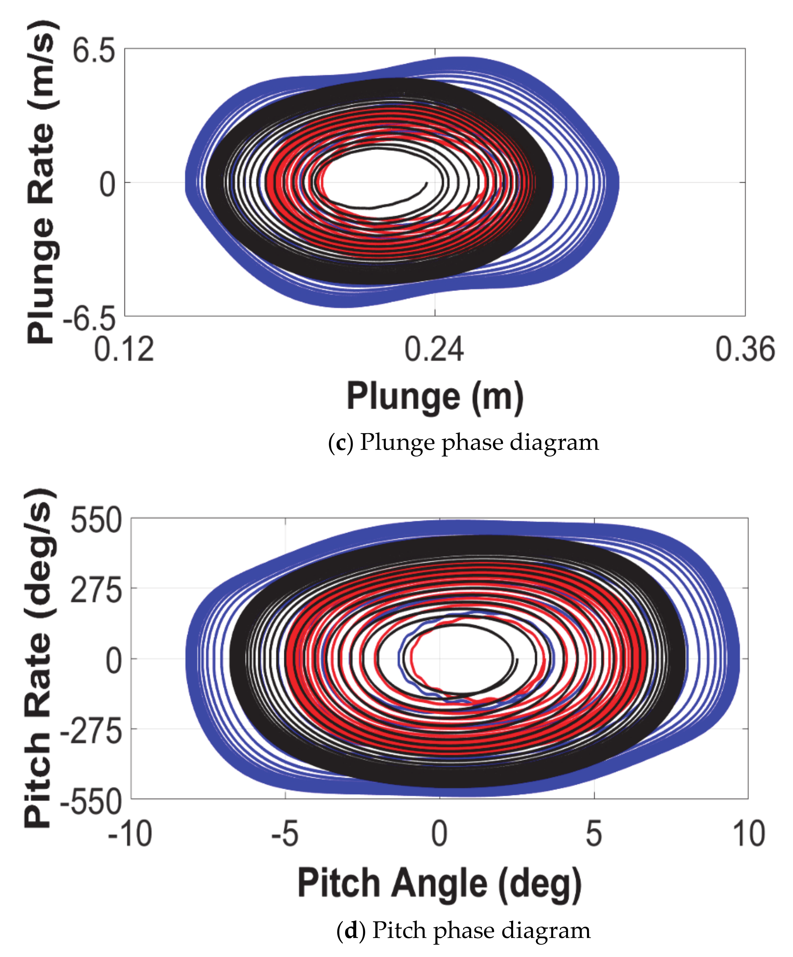
4.2. Limit Cycle Oscillations
- Case 1: 0° flare angle and 0° fold angle;
- Case 2: 0° flare angle and 20° fold angle; and,
- Case 3: 45° flare angle and 20° fold angle.
5. Conclusions
Author Contributions
Funding
Institutional Review Board Statement
Informed Consent Statement
Data Availability Statement
Conflicts of Interest
Abbreviations
| Acronyms | |
| DLM | Doublet Lattice Method |
| DOFs | Degrees Of Freedom |
| FE | Finite Element |
| FHFWT | Flared Hinge Folding Wingtips |
| LCO | Limit Cycle Oscillation |
| RBM | Root Bending Moment |
| RSHF | Root Shear Force |
| SAH | Semi Aeroelastic Hinge |
| Nomenclature | |
| warping constant | |
| strain energy | |
| kinetic energy | |
| flight profile alleviation factor | |
| shape function | |
| design gust velocity | |
| reference gust velocity | |
| nondimensional position of elastic axis relative to half chord | |
| distance between SC and center of gravity | |
| mass per unit length | |
| gust profile | |
| fold angle | |
| hinge-line angle (or flare angle) | |
| global structural inertia matrix | |
| global aerodynamic damping matrix | |
| global aerodynamic stiffness matrix | |
| global structural damping matrix | |
| global structural stiffness matrix | |
| X | generalized coordinates vector |
| Young’s modulus | |
| spanwise bending rigidity | |
| GJ | torsional rigidity |
| H | gust gradient |
| torsion constant | |
| V | true airspeed |
| half chord | |
| lift per unit span | |
| pitch moment per unit span | |
| reduced frequency | |
| length of a beam element | |
| time | |
| plunge displacement | |
| W | work |
| spanwise position along the beam | |
| change in geometric incidence | |
| pitch/twist rotation | |
| bending rotation | |
| air density | |
| frequency | |
| Superscripts | |
| b | bending |
| t | torsion |
| T | transpose |
| . | first derivatives with respect to time |
| .. | second derivatives with respect to time |
| Subscripts | |
| e | ends of the beam element |
| o | amplitude |
Appendix A
References
- Ajaj, R.M. Flight Dynamics of Transport Aircraft Equipped with Flared-Hinge Folding Wingtips. J. Aircr. 2020, 1–13. [Google Scholar] [CrossRef]
- Ajaj, R.M.; Parancheerivilakkathil, M.S.; Amoozgar, M.R.; Friswell, M.I.; Cantwell, W.J. Recent developments in the aeroelasticity of morphing aircraft. Prog. Aerosp. Sci. 2021, 120, 100682. [Google Scholar] [CrossRef]
- Wilson, T.; Azabal, A.; Castrichini, A.; Cooper, J.; Ajaj, R.; Herring, M. Aeroelastic behaviour of hinged wing tips. In Proceedings of the International Forum on Aeroelasticity and Structural Dynamics, IFASD 2017, Como, Italy, 25–28 June 2017. [Google Scholar]
- Castrichini, A.; Siddaramaiah, V.H.; Calderon, D.; Cooper, J.; Wilson, T.; Lemmens, Y. Preliminary investigation of use of flexible folding wing tips for static and dynamic load alleviation. Aeronaut. J. 2017, 121, 73–94. [Google Scholar] [CrossRef] [Green Version]
- Castrichini, A.; Siddaramaiah, V.H.; Calderon, D.; Cooper, J.E.; Wilson, T.; Lemmens, Y. Nonlinear folding wing tips for gust loads alleviation. J. Aircr. 2016, 53, 1391–1399. [Google Scholar] [CrossRef] [Green Version]
- Castrichini, A.; Cooper, J.E.; Wilson, T.; Carrella, A.; Lemmens, Y. Nonlinear negative stiffness wingtip spring device for gust loads alleviation. J. Aircr. 2017, 54, 627–641. [Google Scholar] [CrossRef]
- Cheung, R.C.; Rezgui, D.; Cooper, J.E.; Wilson, T. Testing of a hinged wingtip device for gust loads alleviation. J. Aircr. 2018, 55, 2050–2067. [Google Scholar] [CrossRef]
- Castrichini, A.; Wilson, T.; Saltari, F.; Mastroddi, F.; Viceconti, N.; Cooper, J. Aeroelastics Flight Dynamics Coupling Effects of the Semi-Aeroelastic Hinge Device. J. Aircr. 2020, 57, 333–341. [Google Scholar] [CrossRef]
- Saltari, F.; Riso, C.; Matteis, G.D.; Mastroddi, F. Finite-element-based modeling for flight dynamics and aeroelasticity of flexible aircraft. J. Aircr. 2017, 54, 2350–2366. [Google Scholar] [CrossRef]
- Wilson, T.; Kirk, J.; Hobday, J.; Castrichini, A. Small scale flying demonstration of semi aeroelastic hinged wing tips. In Proceedings of the International Forum on Aeroelasticity and Structural Dynamics IFASD 2019, Savannah, GA, USA, 10–13 June 2019. [Google Scholar]
- Mei, C. Coupled vibrations of thin-walled beams of open section using the finite element method. Int. J. Mech. Sci. 1970, 12, 883–891. [Google Scholar] [CrossRef]
- Qu, Z.-Q.; Jung, Y.; Selvam, R. Model condensation for non-classically damped systems—Part I: Static condensation. Mech. Syst. Signal Process. 2003, 17, 1003–1016. [Google Scholar] [CrossRef]
- Theodorsen, T. General Theory of Aerodynamic Instability and the Mechanism of Flutter; Technical Report, No.496; NACA: Boston, MA, USA, 1935. [Google Scholar]
- Fung, Y.C. Fundamentals of Flutter Analysis. In An Introduction to the Theory of Aeroelasticity; Dover Publications Inc.: Mineola, NY, USA, 1993; p. 205. [Google Scholar]
- Wright, R.J.; Cooper, E.J. Introduction to Aircraft Aeroelasticity and Loads; John Wiley & Sons Ltd.: Hoboken, NJ, USA, 2007. [Google Scholar]
- Hassig, H.J. An approximate true damping solution of the flutter equation by determinant iteration. J. Aircr. 1971, 8, 885–889. [Google Scholar] [CrossRef]
- Ajaj, R.M.; Friswell, M.I. Aeroelasticity of compliant span morphing wings. Smart Mater. Struct. 2018, 27, 1–16. [Google Scholar] [CrossRef] [Green Version]
- Patil, M.J.; Hodges, D.H.; Cesnik, C.E. Nonlinear aeroelasticity and flight dynamics of high-altitude long-endurance aircraft. J. Aircr. 2001, 38, 88–94. [Google Scholar] [CrossRef]
- Patil, M.J.; Hodges, D.H.; Cesnik, C.E. Nonlinear aeroelastic analysis of complete aircraft in subsonic flow. J. Aircr. 2000, 37, 753–760. [Google Scholar] [CrossRef] [Green Version]
- Raghavan, B.; Patil, M.J. Flight dynamics of high aspect-ratio flying wings: Effect of large trim deformation. J. Aircr. 2009, 46, 1808–1812. [Google Scholar] [CrossRef] [Green Version]
- Patil, M.; Patil, M. Aeroelastic tailoring of composite box beams. In Proceedings of the AIAA, 35th Aerospace Sciences Meeting and Exhibit, Reno, NV, USA, 6–9 January 1997; pp. 1–9. [Google Scholar] [CrossRef]
- Huang, R.; Qiu, Z. Transient aeroelastic responses and flutter analysis of a variable-span wing during the morphing process. Chin. J. Aeronaut. 2013, 26, 1430–1438. [Google Scholar] [CrossRef] [Green Version]
- Dimitriadis, G. Introduction to Nonlinear Aeroelasticity, 1st ed.; Wiley & Sons Ltd.: Hoboken, NJ, USA, 2017. [Google Scholar]
- Bogacki, P.; Shampine, L.F. A 3 (2) pair of Runge-Kutta formulas. Appl. Math. Lett. 1989, 2, 321–325. [Google Scholar] [CrossRef] [Green Version]
- Shampine, L.F.; Reichelt, M.W. The matlab ode suite. SIAM J. Sci. Comput. 1997, 18, 1–22. [Google Scholar] [CrossRef] [Green Version]


| DOFs | Case 1 | Case 2 | Case 3 | Case 4 | Case 5 | Case 6 |
|---|---|---|---|---|---|---|
| w1 | 1 | 0 | 0 | 0 | 0 | 0 |
| φ1 | 0 | 1 | 0 | 0 | 0 | 0 |
| θ1 | 0 | 0 | 1 | 0 | 0 | 0 |
| w2 | 0 | 0 | 0 | 1 | 0 | 0 |
| φ2 | 0 | 0 | 0 | 0 | 1 | 0 |
| θ2 | 0 | 0 | 0 | 0 | 0 | 1 |
| Specifications | HALE Wing | Goland Wing | Representative Wing |
|---|---|---|---|
| Half span (m) | 16 | 6.096 | 3 |
| (m) | 1 | 1.8288 | 1 |
| (kg/m) | 0.75 | 35.71 | 6 |
| Moment of inertia per unit length (kgm) | 0.1 | 8.64 | 0.75 |
| Spanwise elastic axis (from LE) | 50% | 33% | 35% |
| Center of gravity (from LE) | 50% | 43% | 45% |
| (Nm2) | 2 × 10⁴ | 9.77 × 10⁶ | 6 × 10⁵ |
| (Nm2) | 1 × 10⁴ | 0.987 × 10⁶ | 6 × 10⁴ |
| (kg/m3) | 0.0889 | 1.225 | 1.225 |
| Wing | Method | ||||||
|---|---|---|---|---|---|---|---|
| Present Work (First 8 Modes) | Ref. [17] | Ref. [18] | Ref. [19] | Ref. [20] | Ref. [21] | Ref. [22] | |
| HALE Wing | |||||||
| Flutter Speed (m/s) | 32.61 | 33.43 | 32.21 | − | − | 32.51 | − |
| Flutter Freq. (rad/s) | 22.27 | 21.38 | 22.61 | − | − | 22.37 | − |
| Divergence Speed (m/s) | 37.34 | 37.18 | 37.29 | − | − | 37.15 | − |
| Goland Wing | |||||||
| Flutter Speed (m/s) | 136.99 | 137.11 | − | 135.60 | 136.22 | 137.16 | 133 |
| Flutter Freq. (rad/s) | 69.97 | 69.90 | − | 70.20 | 70.06 | 70.70 | 72.70 |
| Divergence Speed (m/s) | 252.46 | 252.80 | − | − | 250.82 | − | − |
| Representative Wing | |||||||
| Flutter Speed (m/s) | 79.07 | 78.33 | − | − | − | − | 77 |
| Flutter Freq. (rad/s) | 149.60 | 148.94 | − | − | − | − | 149.60 |
| Divergence Speed (m/s) | 207.34 | 206.70 | − | − | − | − | − |
Publisher’s Note: MDPI stays neutral with regard to jurisdictional claims in published maps and institutional affiliations. |
© 2021 by the authors. Licensee MDPI, Basel, Switzerland. This article is an open access article distributed under the terms and conditions of the Creative Commons Attribution (CC BY) license (https://creativecommons.org/licenses/by/4.0/).
Share and Cite
Ajaj, R.M.; Saavedra Flores, E.I.; Amoozgar, M.; Cooper, J.E. A Parametric Study on the Aeroelasticity of Flared Hinge Folding Wingtips. Aerospace 2021, 8, 221. https://doi.org/10.3390/aerospace8080221
Ajaj RM, Saavedra Flores EI, Amoozgar M, Cooper JE. A Parametric Study on the Aeroelasticity of Flared Hinge Folding Wingtips. Aerospace. 2021; 8(8):221. https://doi.org/10.3390/aerospace8080221
Chicago/Turabian StyleAjaj, Rafic M., Erick I. Saavedra Flores, Mohammadreza Amoozgar, and Jonathan E. Cooper. 2021. "A Parametric Study on the Aeroelasticity of Flared Hinge Folding Wingtips" Aerospace 8, no. 8: 221. https://doi.org/10.3390/aerospace8080221
APA StyleAjaj, R. M., Saavedra Flores, E. I., Amoozgar, M., & Cooper, J. E. (2021). A Parametric Study on the Aeroelasticity of Flared Hinge Folding Wingtips. Aerospace, 8(8), 221. https://doi.org/10.3390/aerospace8080221