A Comparison Study of Marginal and Internal Fit Assessment Methods for Fixed Dental Prostheses

 ,
,  ,
, 

Abstract
:1. Introduction
- (1)
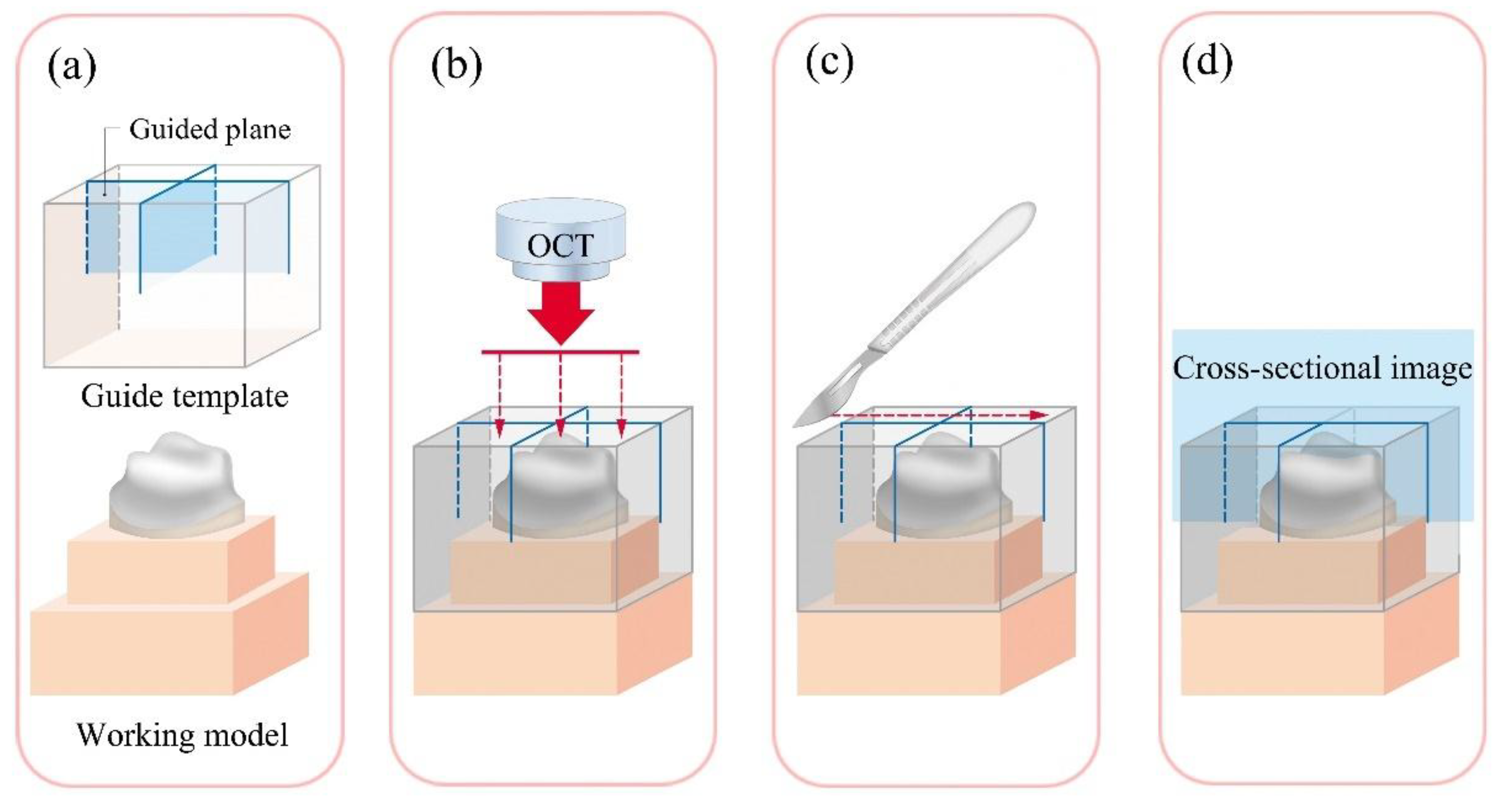
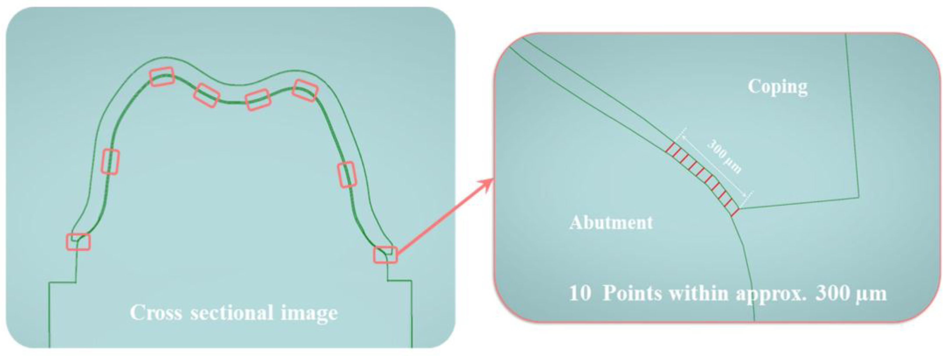
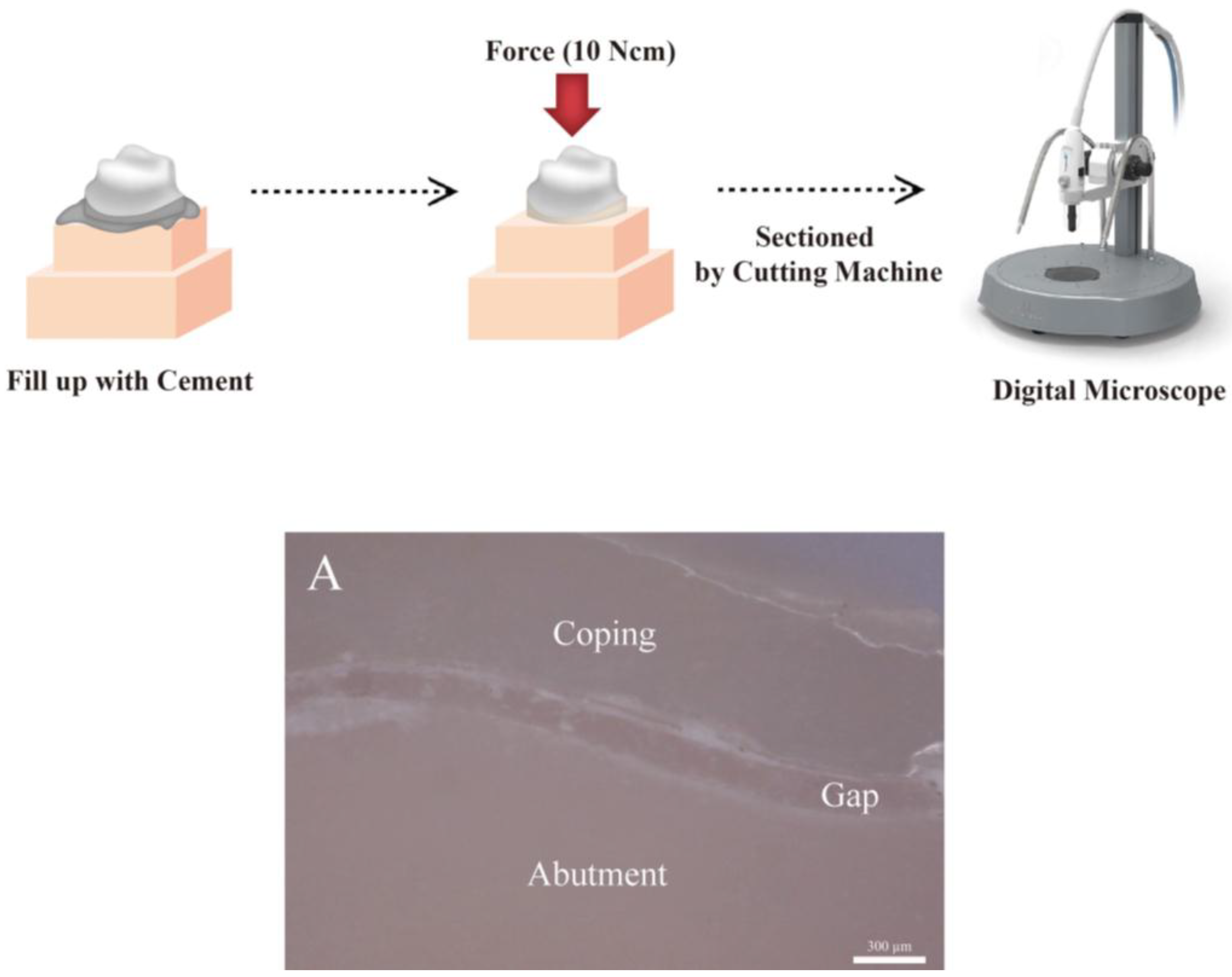
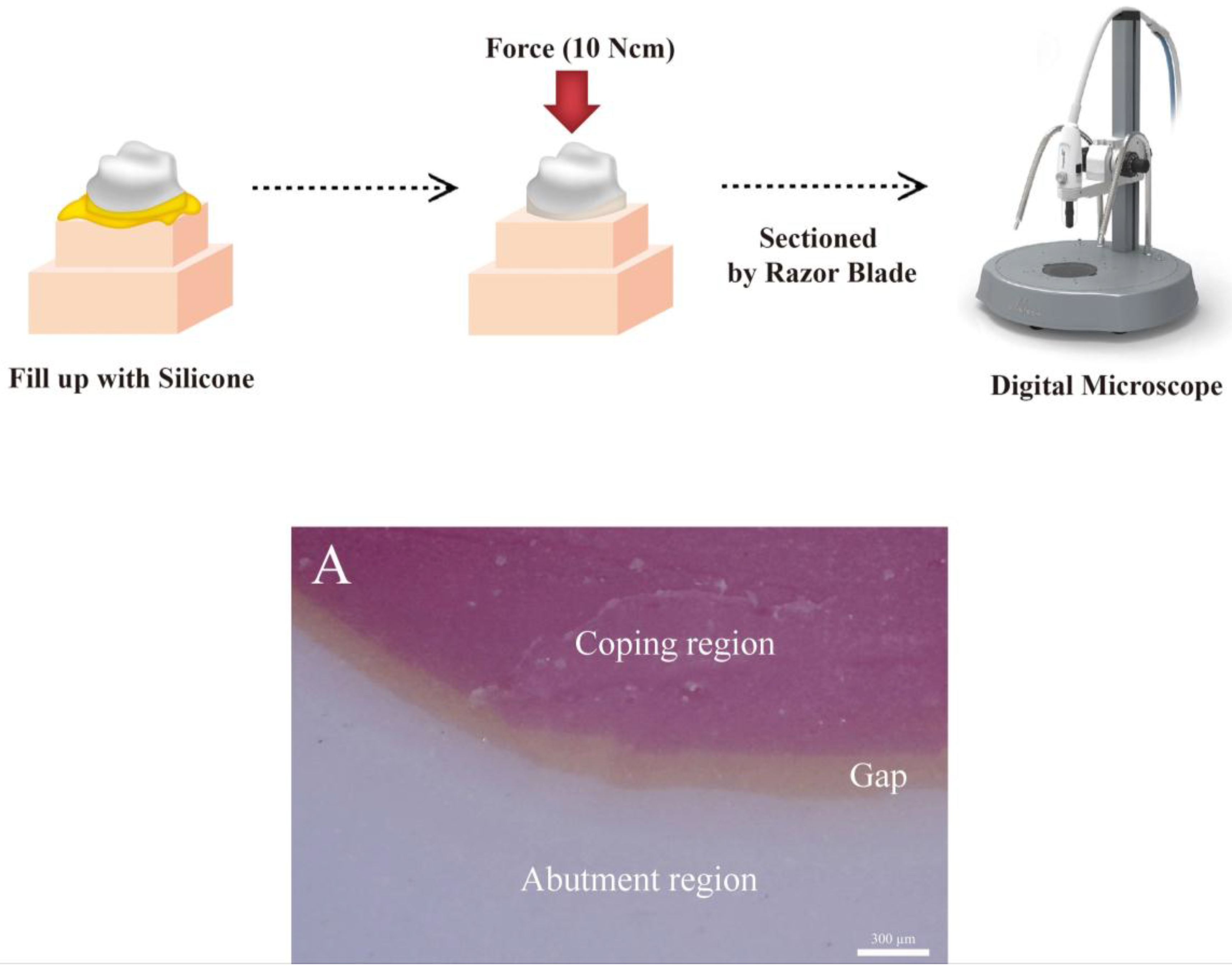
- The cross-sectional method (CSM): the CSM is a method in which after cementation, the desired part of the prosthesis is cut and measured with an optical or electronic microscope. Since the actual prosthesis is cut and measured, it has the advantage of allowing accurate measurement of the internal and marginal fit of the prosthesis. However, the disadvantages are that the method requires the samples to be destroyed, and the measurements cannot be made directly in the oral cavity [11,12,29].
- (2)
- The silicone replica technique (SRT): SRT is performed using the same protocol as cementation of a prosthesis. However, the method involves injecting silicone instead of cement inside the prosthesis and duplicating the internal and marginal fit for measurement. Since this is a relatively simple, low-cost method allowing the measurements to be made directly in the oral cavity, it has been utilized in many studies [21,22,23,24,25,26,30]. However, there is a possibility of deformation and tearing of the impression materials [31,32,33,34]. Additionally, CSM and SRT can make assessments only using two-dimensional (2D) analysis.
- (3)
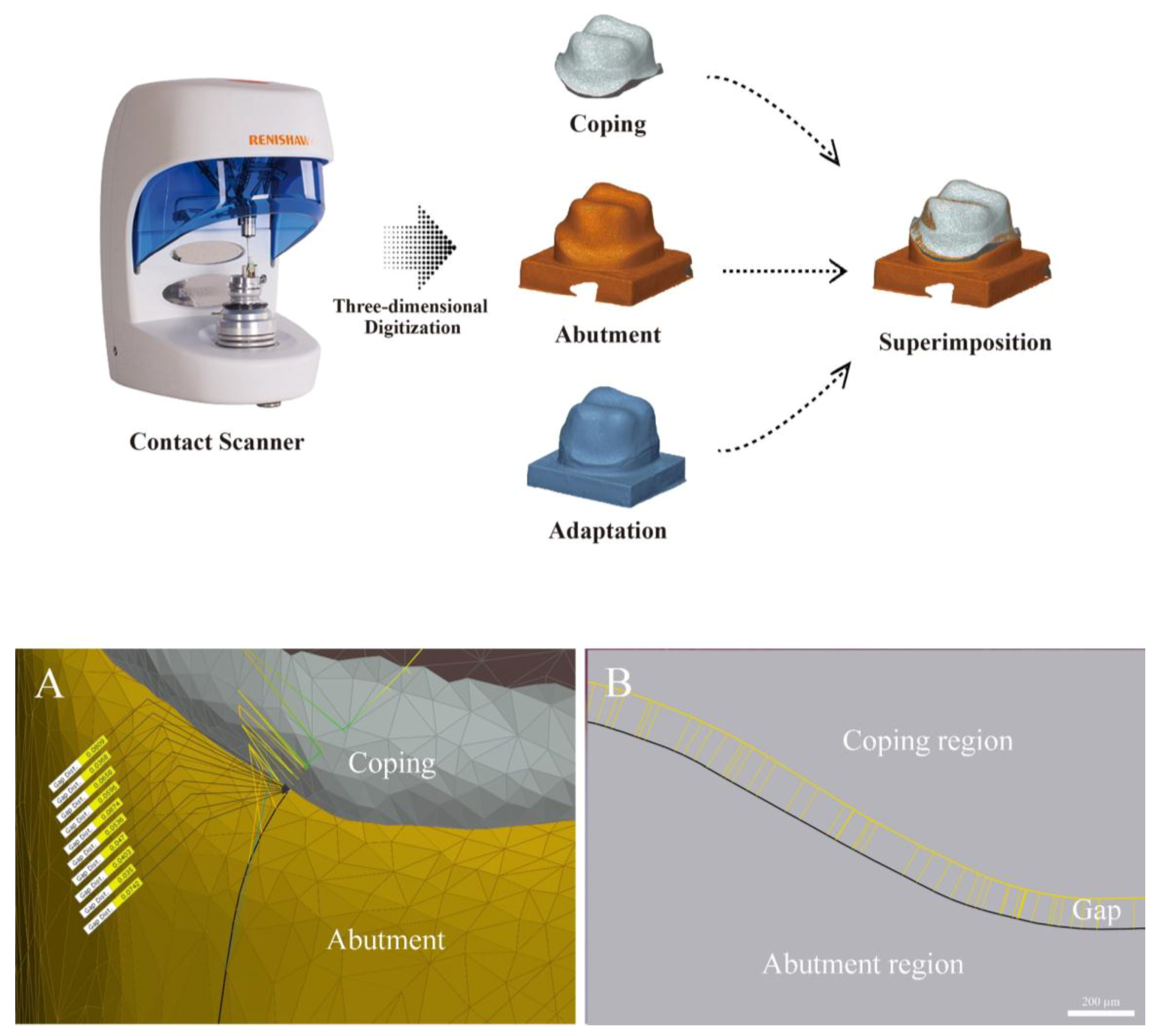
- The triple scan method (TSM): the TSM is a method of scanning the internal and external aspects of the prosthesis, the abutment tooth, and the prosthesis at the try-in stage in order to obtain three-dimensional (3D) data and measure the marginal and internal fit by overlapping the 3D data on an analysis software. It is a non-destructive, non-radioactive method capable of providing reproducible results at any time by scanning the data. However, miscalculations may occur due to possible inaccuracy and overlapping of the scanned data [27,28,34,35].
- (4)
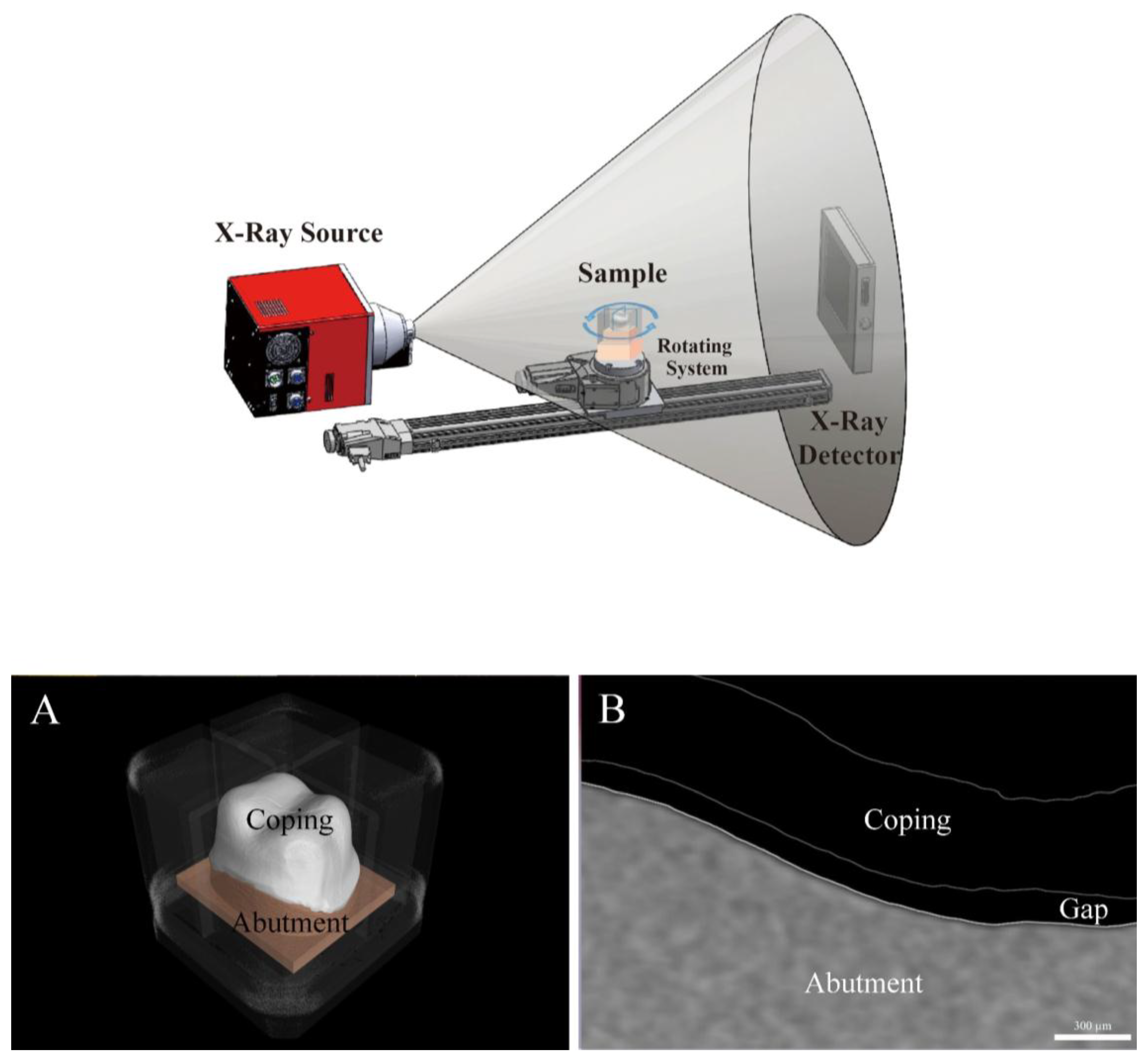
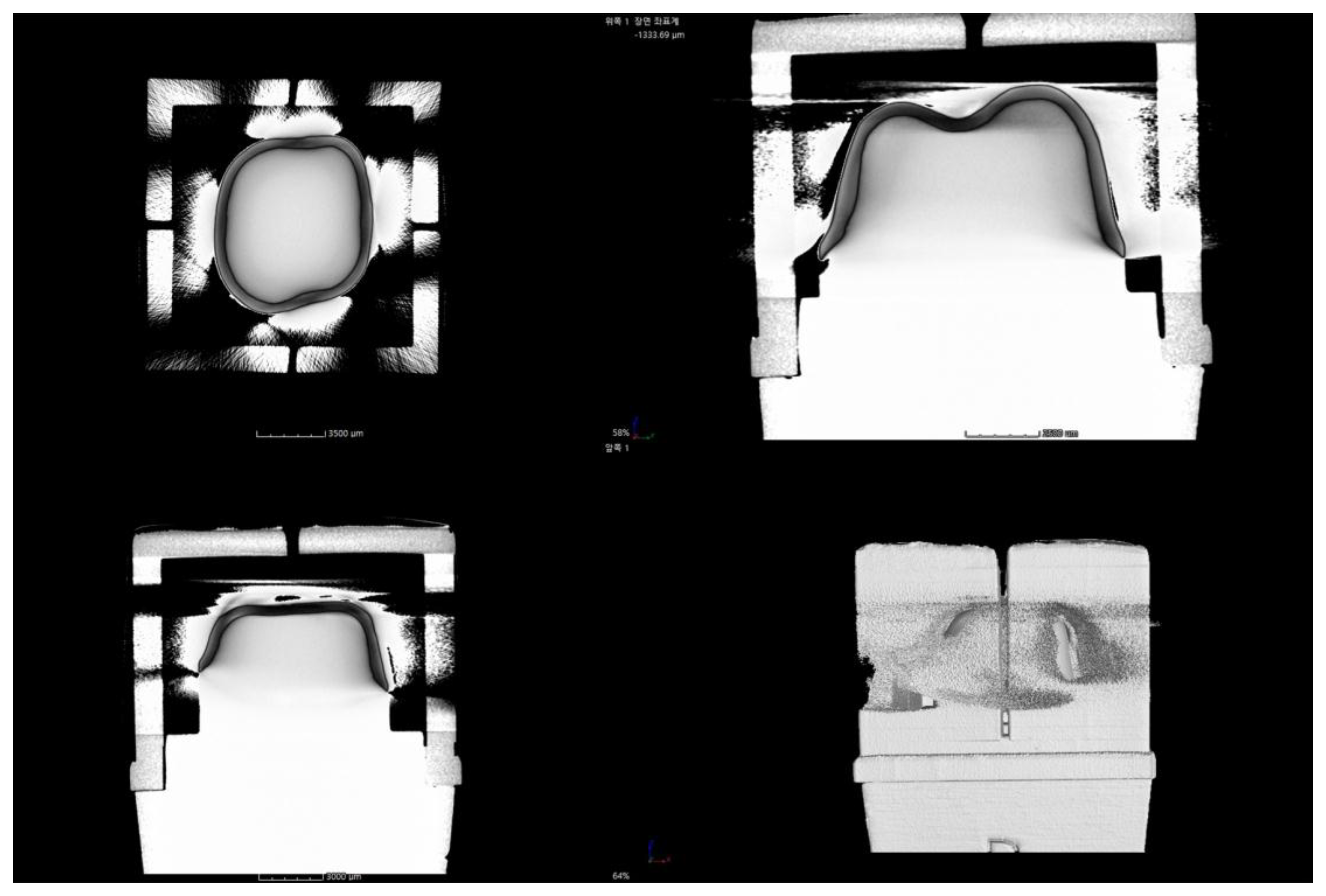
- Micro-computed tomography (MCT): MCT measures the internal and marginal fit of the prosthesis using radiography. The merits of this method include a high resolution and the ability to measure the desired parts by obtaining 3D images. However, the disadvantages of this method include the difficulty to measure metallic prostheses due to the presence of artifacts and an increased risk of exposure to radiation [3,4,13,14,15,21,36].
- (5)
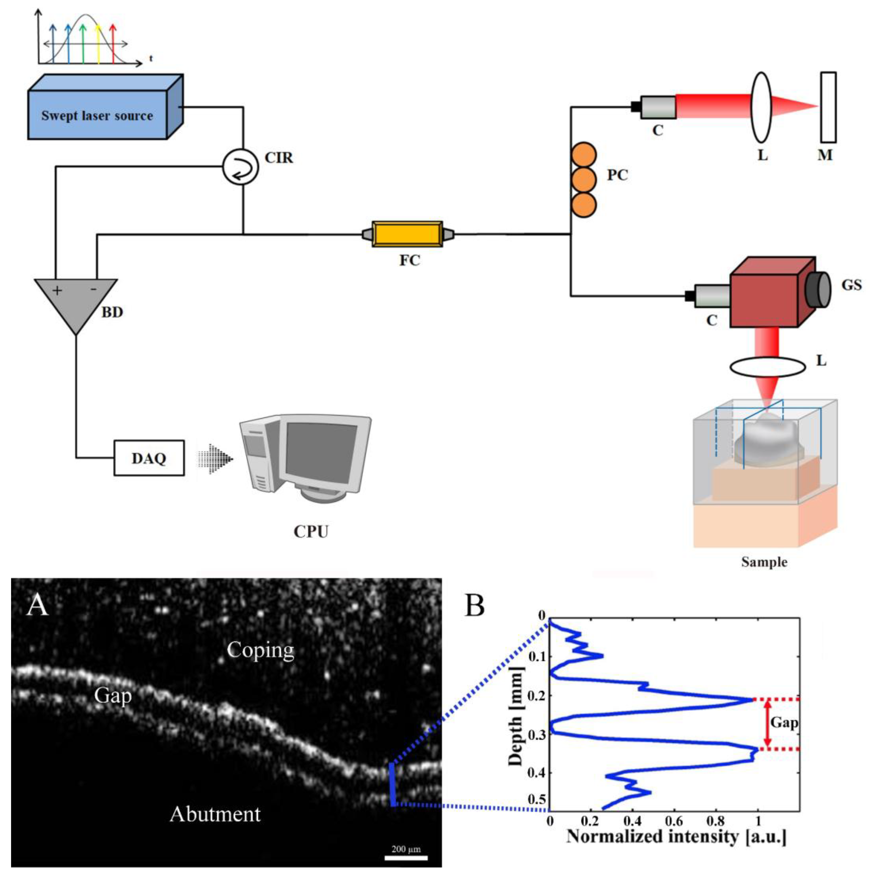
- Optical coherence tomography (OCT): OCT is a method of measurement using higher resolution 2D or 3D images in optical scattering media using coherent light. This is a non-destructive, non-radiological method with the advantage of allowing the acquisition of higher resolution images in real time, which are often utilized for in vivo research [37]. On the other hand, its disadvantage includes difficulty in measuring very thick or optical-opaque materials [16,17,18,19,20,21]. Both 2D and 3D analysis are possible with TSM, MCT, and OCT.
2. Materials and Methods
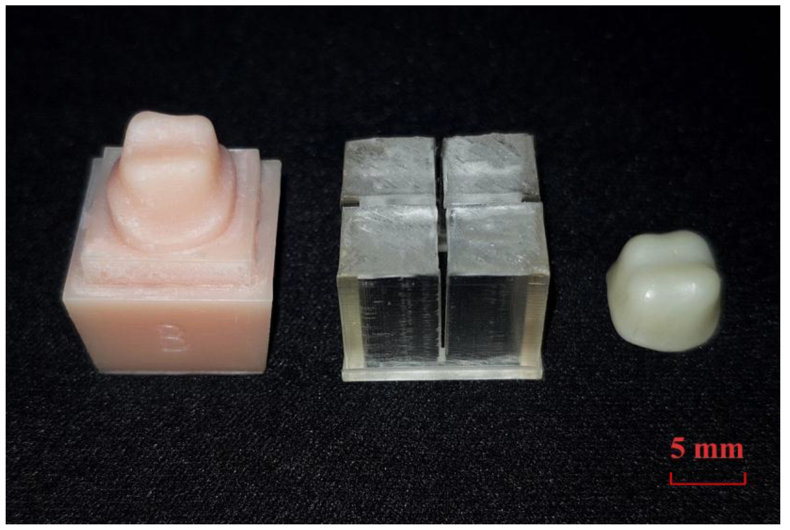
2.1. Sample Preparation
2.2. Marginal and Internal Fit Assessment
2.2.1. Cross-Sectional Method (CSM Group)
2.2.2. Silicone Replica Technique (SRT Group)
2.2.3. Triple Scan Method (TSM Group)
2.2.4. Micro-Computed Tomography (MCT Group)
2.2.5. Optical Coherence Tomography (OCT Group)
2.3. Statistical Analysis
3. Results
4. Discussion
5. Conclusions
Author Contributions
Funding
Acknowledgments
Conflicts of Interest
References
- Kim, D.Y.; Kim, J.H.; Kim, H.Y.; Kim, W.C. Comparison and evaluation of marginal and internal gaps in cobalt–chromium alloy copings fabricated using subtractive and additive manufacturing. J. Prosthodont. Res. 2018, 62, 56–64. [Google Scholar] [CrossRef]
- Akçin, E.T.; Güncü, M.B.; Aktaş, G.; Aslan, Y. Effect of manufacturing techniques on the marginal and internal fit of cobalt-chromium implant-supported multiunit frameworks. J. Prosthet. Dent. 2018, 120, 715–720. [Google Scholar] [CrossRef] [PubMed]
- Dauti, R.; Cvikl, B.; Lilaj, B.; Heimel, P.; Moritz, A.; Schedle, A. Micro-CT evaluation of marginal and internal fit of cemented polymer infiltrated ceramic network material crowns manufactured after conventional and digital impressions. J. Prosthodont. Res. 2018, 63, 40–46. [Google Scholar] [CrossRef] [PubMed]
- Alharbi, N.; Alharbi, S.; Cuijpers, V.M.; Osman, R.B.; Wismeijer, D. Three-dimensional evaluation of marginal and internal fit of 3D-printed interim restorations fabricated on different finish line designs. J. Prosthodont. Res. 2018, 62, 218–226. [Google Scholar] [CrossRef]
- Ariganello, M.B.; Guadarrama Bello, D.; Rodriguez-Contreras, A.; Sadeghi, S.; Isola, G.; Variola, F.; Nanci, A. Surface nanocavitation of titanium modulates macrophage activity. Int. J. Nanomed. 2018, 13, 8297–8308. [Google Scholar] [CrossRef] [PubMed]
- Hagenfeld, D.; Mutters, N.T.; Harks, I.; Koch, R.; Kim, T.S.; Prehm, P. Hyaluronan-mediated mononuclear leukocyte binding to gingival fibroblasts. Clin. Oral Investig. 2018, 22, 1063–1070. [Google Scholar] [CrossRef]
- Matarese, G.; Ramaglia, L.; Fiorillo, L.; Cervino, G.; Lauritano, F.; Isola, G. Implantology and Periodontal Disease: The Panacea to Problem Solving? Open Dent. J. 2017, 11, 460–465. [Google Scholar] [CrossRef]
- Martins, L.M.; Lorenzoni, F.C.; Melo, A.O.D.; Silva, L.M.D.; Oliveira, J.L.G.D.; Oliveira, P.C.G.D.; Bonfante, G. Internal fit of two all-ceramic systems and metal-ceramic crowns. J. Appl. Oral Sci. 2012, 20, 235–240. [Google Scholar] [CrossRef] [Green Version]
- Sundar, M.K.; Chikmagalur, S.B.; Pasha, F. Marginal fit and microleakage of cast and metal laser sintered copings-An in vitro study. J. Prosthodont. Res. 2014, 58, 252–258. [Google Scholar] [CrossRef]
- Farronato, D.; Pieroni, S.; Mangano, F.G.; Briguglio, F.; Re, D. Effects of different abutment material and surgical insertion torque on the marginal adaptation of an internal conical interface: An in vitro study. J. Prosthodont. Res. 2014, 58, 230–236. [Google Scholar] [CrossRef]
- Sachs, C.; Groesser, J.; Stadelmann, M.; Schweiger, J.; Erdelt, K.; Beuer, F. Full-arch prostheses from translucent zirconia: Accuracy of fit. Dent. Mater. 2014, 30, 817–823. [Google Scholar] [CrossRef]
- Acquaviva, P.; Madini, L.; Nembrini, E.; Brazzoli, S.; Papacchini, F.; Cerutti, F.A. Marginal adaptation of new bulk fill composites: Microscopical evaluation. Dent. Mater. 2014, 30, e125. [Google Scholar] [CrossRef]
- Park, S.; Jung, J.; Han, S. Internal and marginal adaptation of bulk-filled composites. Dent. Mater. 2015, 31, e17–e18. [Google Scholar] [CrossRef]
- Oka, Y.; Sasaki, J.I.; Wakabayashi, K.; Nakano, Y.; Okamura, S.Y.; Nakamura, T.; Imazato, S.; Yatani, H. Fabrication of a radiopaque fit-testing material to evaluate the three-dimensional accuracy of dental prostheses. Dent. Mater. 2016, 32, 921–928. [Google Scholar] [CrossRef]
- Rezende, C.E.E.; Borges, A.F.S.; Macedo, R.M.; Rubo, J.H.; Griggs, J.A. Dimensional changes from the sintering process and fit of Y-TZP copings: Micro-CT analysis. Dent. Mater. 2017, 33, e405–e413. [Google Scholar] [CrossRef]
- Monteiro, G.Q.; Montes, M.A.; Gomes, A.S.; Mota, C.C.; Campello, C.C.; Freitas, A.Z. Marginal analysis of resin composite restorative systems using optical coherence tomography. Dent. Mater. 2011, 27, e213–e223. [Google Scholar] [CrossRef]
- Makishi, P.; Thitthaweerat, S.; Sadr, A.; Shimada, Y.; Giannini, M.; Tagami, J.; Sumi, Y. Marginal adaptation of different adhesive systems to dentin by optical coherence tomography. Dent. Mater. 2013, 29, e46. [Google Scholar] [CrossRef]
- Sadr, A.; Shimada, Y.; Bista, B.; Makishi, P.; Sumi, Y.; Tagami, J. Comparison of tomographic techniques for assessment of marginal and internal microgaps of composites. Dent. Mater. 2013, 29, e55–e56. [Google Scholar] [CrossRef]
- Comba, A.; Ventura, G.; Luganini, A.; Alovisi, M.; Alovisi, C.; Berutti, E.; Scotti, N. OCT evaluation of marginal seal of bulk-fill composites in dentin. Dent. Mater. 2015, 31, e42. [Google Scholar] [CrossRef]
- Comba, A.; Tempesta, R.M.; Ventura, G.; Luganini, A.; Alovisi, C.; Berutti, E.; Scotti, N. Marginal adaptation of composites on dentin with different imaging techniques. Dent. Mater. 2016, 32, e74. [Google Scholar] [CrossRef]
- Han, S.H.; Sadr, A.; Tagami, J.; Park, S.H. Non-destructive evaluation of an internal adaptation of resin composite restoration with swept-source optical coherence tomography and micro-CT. Dent. Mater. 2016, 32, e1–e7. [Google Scholar] [CrossRef]
- Kim, K.B.; Kim, W.C.; Kim, H.Y.; Kim, J.H. An evaluation of marginal fit of three-unit fixed dental prostheses fabricated by direct metal laser sintering system. Dent. Mater. 2013, 29, e91–e96. [Google Scholar] [CrossRef]
- Colpani, J.T.; Borba, M.; Della Bona, Á. Evaluation of marginal and internal fit of ceramic crown copings. Dent. Mater. 2013, 29, 174–180. [Google Scholar] [CrossRef]
- Keul, C.; Stawarczyk, B.; Erdelt, K.J.; Beuer, F.; Edelhoff, D.; Güth, J.F. Fit of 4-unit FDPs made of zirconia and CoCr-alloy after chairside and labside digitalization–a laboratory study. Dent. Mater. 2014, 30, 400–407. [Google Scholar] [CrossRef] [PubMed]
- Piras, F.; Berro-Filho, J.; Rubo, J.; Ferruzzi, F.; Ferrairo, B.; Mosquim, V. Marginal and internal space of metallic copings. Dent. Mater. 2016, 32, e75. [Google Scholar] [CrossRef]
- Schriwer, C.; Skjold, A.; Gjerdet, N.R.; Øilo, M. Monolithic zirconia dental crowns. Internal fit, margin quality, fracture mode and load at fracture. Dent. Mater. 2017, 33, 1012–1020. [Google Scholar] [CrossRef]
- Schaefer, O.; Watts, D.C.; Sigusch, B.W.; Kuepper, H.; Guentsch, A. Marginal and internal fit of pressed lithium disilicate partial crowns in vitro: A three-dimensional analysis of accuracy and reproducibility. Dent. Mater. 2012, 28, 320–326. [Google Scholar] [CrossRef]
- Schaefer, O.; Kuepper, H.; Thompson, G.A.; Cachovan, G.; Hefti, A.F.; Guentsch, A. Effect of CNC-milling on the marginal and internal fit of dental ceramics: A pilot study. Dent. Mater. 2013, 29, 851–858. [Google Scholar] [CrossRef]
- Mitchell, C.A.; Pintado, M.R.; Douglas, W.H. Nondestructive, in vitro quantification of crown margins. J. Prosthet. Dent. 2001, 85, 575–584. [Google Scholar] [CrossRef]
- Praça, L.; Pekam, F.C.; Rego, R.O.; Radermacher, K.; Wolfart, S.; Marotti, J. Accuracy of single crowns fabricated from ultrasound digital impressions. Dent. Mater. 2018, 34, e280–e288. [Google Scholar] [CrossRef] [PubMed]
- Laurent, M.; Scheer, P.; Dejou, J.; Laborde, G. Clinical evaluation of the marginal fit of cast crowns-validation of the silicone replica method. J. Oral Rehabil. 2008, 35, 116–122. [Google Scholar] [CrossRef]
- Coli, P.; Karlsson, S. Fit of a new pressure-sintered zirconium dioxide coping. Int. J. Prosthodont. 2004, 17, 59–64. [Google Scholar]
- Wolfart, S.; Wegner, S.M.; Al-Halabi, A.; Kern, M. Clinical evaluation of marginal fit of a new experimental all-ceramic system before and after cementation. Int. J. Prosthodont. 2003, 16, 587–592. [Google Scholar]
- Park, J.Y.; Bae, S.Y.; Lee, J.J.; Kim, J.H.; Kim, H.Y.; Kim, W.C. Evaluation of the marginal and internal gaps of three different dental prostheses: Comparison of the silicone replica technique and three-dimensional superimposition analysis. J. Adv. Prosthodont. 2017, 9, 159–169. [Google Scholar] [CrossRef]
- Bae, S.Y.; Park, J.Y.; Jeong, I.D.; Kim, H.Y.; Kim, J.H.; Kim, W.C. Three-dimensional analysis of marginal and internal fit of copings fabricated with polyetherketoneketone (PEKK) and zirconia. J. Prosthodont. Res. 2017, 61, 106–112. [Google Scholar] [CrossRef]
- Uzgur, R.; Ercan, E.; Uzgur, Z.; Çolak, H.; Yalçın, M.; Özcan, M. Cement Thickness of Inlay Restorations Made of Lithium Disilicate, Polymer-Infiltrated Ceramic and Nano-Ceramic CAD/CAM Materials Evaluated Using 3D X-Ray Micro-Computed Tomography. J. Prosthodont. 2018, 27, 456–460. [Google Scholar] [CrossRef]
- Pahlevaninezhad, H.; Khorasaninejad, M.; Huang, Y.W.; Shi, Z.; Hariri, L.P.; Adams, D.C.; Ding, V.; Zhu, A.; Qiu, C.W.; Capasso, F. Nano-optic endoscope for high-resolution optical coherence tomography in vivo. Nat. Photonics 2018, 12, 540. [Google Scholar] [CrossRef]
- Lee, K.B.; Park, C.W.; Kim, K.H.; Kwon, T.Y. Marginal and internal fit of all-ceramic crowns fabricated with two different CAD/CAM systems. Dent. Mater. J. 2008, 27, 422–426. [Google Scholar] [CrossRef]
- Boitelle, P.; Tapie, L.; Mawussi, B.; Fromentin, O. Evaluation of the marginal fit of CAD-CAM zirconia copings: Comparison of 2D and 3D measurement methods. J. Prosthet. Dent. 2018, 119, 75–81. [Google Scholar] [CrossRef]
- Zeller, S.; Guichet, D.; Kontogiorgos, E.; Nagy, W.W. Accuracy of three digital workflows for implant abutment and crown fabrication using a digital measuring technique. J. Prosthet. Dent. 2019, 121, 276–284. [Google Scholar] [CrossRef]
- Alajaji, N.K.; Bardwell, D.; Finkelman, M.; Ali, A. Micro-CT Evaluation of Ceramic Inlays: Comparison of the Marginal and Internal Fit of Five and Three Axis CAM Systems with a Heat Press Technique. J. Esthet. Restor. Dent. 2017, 29, 49–58. [Google Scholar] [CrossRef]
- Krämer, N.; Lohbauer, U.; Frankenberger, R. Adhesive luting of indirect restorations. Am. J. Dent. 2000, 13, 60D–76D. [Google Scholar]
- Roperto, R.; Assaf, H.; Soares-Porto, T.; Lang, L.; Teich, S. Are different generations of CAD/CAM milling machines capable to produce restorations with similar quality? J. Clin. Exp. Dent. 2016, 8, e423–e428. [Google Scholar] [CrossRef]
- Goujat, A.; Abouelleil, H.; Colon, P.; Jeannin, C.; Pradelle, N.; Seux, D.; Grosgogeat, B. Marginal and internal fit of CAD-CAM inlay/onlay restorations: A systematic review of in vitro studies. J. Prosthet. Dent. 2018. [Google Scholar] [CrossRef]
- Kale, E.; Seker, E.; Yilmaz, B.; Özcelik, T.B. Effect of cement space on the marginal fit of CAD-CAM-fabricated monolithic zirconia crowns. J. Prosthet. Dent. 2016, 116, 890–895. [Google Scholar] [CrossRef]
- Sailer, I.; Fehér, A.; Filser, F.; Gauckler, L.J.; Lüthy, H.; Hämmerle, C.H.F. Five-year clinical results of zirconia frameworks for posterior fixed partial dentures. Int. J. Prosthodont. 2007, 20, 383–388. [Google Scholar]
- Holmes, J.R.; Bayne, S.C.; Holland, G.A.; Sulik, W.D. Considerations in measurement of marginal fit. J. Prosthet. Dent. 1989, 62, 405–408. [Google Scholar] [CrossRef]
- Mai, H.N.; Lee, K.E.; Ha, J.H.; Lee, D.H. Effects of image and education on the precision of the measurement method for evaluating prosthesis misfit. J. Prosthet. Dent. 2018, 119, 600–605. [Google Scholar] [CrossRef]
- Quintas, A.F.; Oliveira, F.; Bottino, M.A. Vertical marginal discrepancy of ceramic copings with different ceramic materials, finish lines, and luting agents: An in vitro evaluation. J. Prosthet. Dent. 2004, 92, 250–257. [Google Scholar] [CrossRef]
- Matta, R.E.; Schmitt, J.; Wichmann, M.; Holst, S. Circumferential fit assessment of CAD/CAM single crowns-A pilot investigation on a new virtual analytical protocol. Quintessence Int. 2012, 43, 801–809. [Google Scholar]
- Fercher, A.F.; Drexler, W.; Hitzenberger, C.K.; Lasser, T. Optical coherence tomography-principles and applications. Rep. Prog. Phys. 2003, 66, 239–301. [Google Scholar] [CrossRef]
- Schaefer, O.; Decker, M.; Wittstock, F.; Kuepper, H.; Guentsch, A. Impact of digital impression techniques on the adaption of ceramic partial crowns in vitro. J. Dent. 2014, 42, 677–683. [Google Scholar] [CrossRef]
- Akın, A.; Toksavul, S.; Toman, M. Clinical marginal and internal adaptation of maxillary anterior single all-ceramic crowns and 2-year randomized controlled clinical trial. J. Prosthodont. 2015, 24, 345–350. [Google Scholar] [CrossRef]
- Anadioti, E.; Aquilino, S.A.; Gratton, D.G.; Holloway, J.A.; Denry, I.L.; Thomas, G.W.; Qian, F. Internal fit of pressed and computer-aided design/computer-aided manufacturing ceramic crowns made from digital and conventional impressions. J. Prosthet. Dent. 2015, 13, 304–309. [Google Scholar] [CrossRef]
- Goujat, A.; Abouelleil, H.; Colon, P.; Jeannin, C.; Pradelle, N.; Seux, D.; Grosgogeat, B. Mechanical properties and internal fit of 4 CAD-CAM block materials. J. Prosthet. Dent. 2018, 119, 384–389. [Google Scholar] [CrossRef]
- Mously, H.A.; Finkelman, M.; Zandparsa, R.; Hirayama, H. Marginal and internal adaptation of ceramic crown restorations fabricated with CAD/CAM technology and the heat-press technique. J. Prosthet. Dent. 2014, 112, 249–256. [Google Scholar] [CrossRef]
- Lins, L.; Bemfica, V.; Queiroz, C.; Canabarro, A. In vitro evaluation of the internal and marginal misfit of CAD/CAM zirconia copings. J. Prosthet. Dent. 2015, 113, 205–211. [Google Scholar] [CrossRef]
- El Ghoul, W.A.; Özcan, M.; Ounsi, H.; Tohme, H.; Salameh, Z. Effect of different CAD-CAM materials on the marginal and internal adaptation of endocrown restorations: An in vitro study. J. Prosthet. Dent. 2019. [Google Scholar] [CrossRef]
- Fransson, B.; Øilo, G.; Gjeitanger, R. The fit of metal-ceramic crowns, a clinical study. Dent. Mater. 1985, 1, 197–199. [Google Scholar] [CrossRef]
- Park, J.M.; Hämmerle, C.H.; Benic, G.I. Digital technique for in vivo assessment of internal and marginal fit of fixed dental prostheses. J. Prosthet. Dent. 2017, 118, 452–454. [Google Scholar] [CrossRef] [Green Version]
- Lenton, P.; Rudney, J.; Chen, R.; Fok, A.; Aparicio, C.; Jones, R.S. Imaging in vivo secondary caries and ex vivo dental biofilms using cross-polarization optical coherence tomography. Dent. Mater. 2012, 28, 792–800. [Google Scholar] [CrossRef] [PubMed] [Green Version]


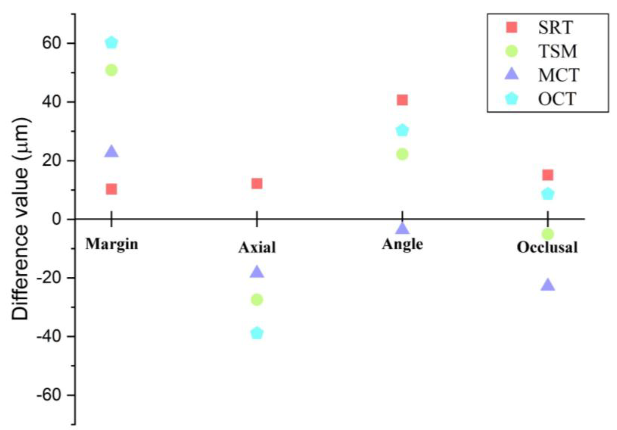
| Test method | Margin | Axial | Angle | Occlusal |
|---|---|---|---|---|
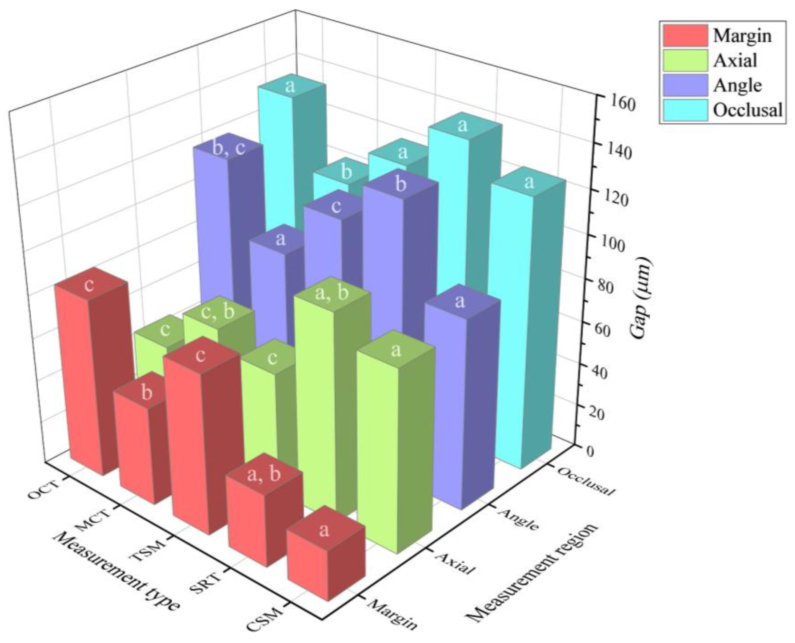
| CSM | 23.2 ± 5.3 a | 83.7 ± 19.8 a | 87.9 ± 17.2 a | 125.4 ± 13.7 a |
| SRT | 33.5 ± 12.1 a,b | 95.9 ± 52.9 a,b | 128.6 ± 17.3 b | 140.5 ± 33.3 a |
| TSM | 74.1 ± 26.1 c | 56.3 ± 30.1 c | 110.1 ± 13.9 c | 120.3 ± 20.9 a |
| MCT | 45.9 ± 25.9 b | 65.3 ± 47.7 c,b | 84.3 ± 20.2 a | 102.6 ± 12.8 b |
| OCT | 83.4 ± 22.1 c | 44.8 ± 14.5 c | 118.2 ± 22.2 b,c | 134 ± 18.9 a |
| Pros and Cons | CSM | SRT | TSM | MCT | OCT |
|---|---|---|---|---|---|
| Use in the oral cavity | X | ○ | ○ | X | △ |
| Economics | △ | ○ | △ | X | X |
| Accessibility in a clinical environment | △ | ○ | ○ | X | X |
| Various indications | ○ | ○ | ○ | △ | △ |
| Reliability through previous studies | ○ | ○ | △ | ○ | △ |
© 2019 by the authors. Licensee MDPI, Basel, Switzerland. This article is an open access article distributed under the terms and conditions of the Creative Commons Attribution (CC BY) license (http://creativecommons.org/licenses/by/4.0/).
Share and Cite
Son, K.; Lee, S.; Kang, S.H.; Park, J.; Lee, K.-B.; Jeon, M.; Yun, B.-J. A Comparison Study of Marginal and Internal Fit Assessment Methods for Fixed Dental Prostheses. J. Clin. Med. 2019, 8, 785. https://doi.org/10.3390/jcm8060785
Son K, Lee S, Kang SH, Park J, Lee K-B, Jeon M, Yun B-J. A Comparison Study of Marginal and Internal Fit Assessment Methods for Fixed Dental Prostheses. Journal of Clinical Medicine. 2019; 8(6):785. https://doi.org/10.3390/jcm8060785
Chicago/Turabian StyleSon, Keunbada, Sangbong Lee, Seok Hyon Kang, Jaeseok Park, Kyu-Bok Lee, Mansik Jeon, and Byoung-Ju Yun. 2019. "A Comparison Study of Marginal and Internal Fit Assessment Methods for Fixed Dental Prostheses" Journal of Clinical Medicine 8, no. 6: 785. https://doi.org/10.3390/jcm8060785
APA StyleSon, K., Lee, S., Kang, S. H., Park, J., Lee, K.-B., Jeon, M., & Yun, B.-J. (2019). A Comparison Study of Marginal and Internal Fit Assessment Methods for Fixed Dental Prostheses. Journal of Clinical Medicine, 8(6), 785. https://doi.org/10.3390/jcm8060785