Abstract
Solar air heater is considered to be the most popular and widely used solar thermal system. Solar air heater (SAH) can be used in many applications, ranging from domestic to industrial purposes. However, it seems that the viability of SAH is not feasible due to the following two reasons: (i) the low convective heat transfer coefficient at the absorber plate is the reason that causes a low heat transfer rate to the flowing air, and (ii) the high temperature of the absorber plate insists on high heat losses, thus, reducing the thermal efficiency. The convective coefficient can be augmented by placing turbulators/roughness on the absorber plate, which induces turbulence in the flow passage near the absorber plate by disrupting and destabilizing the laminar sublayer. This comprehensive review has been presented to summarize the studies on artificial roughness/turbulators geometries to enhance the heat transfer rate. Various rib configurations (such as grits, grooves, blockages, baffles, winglets, protrusions, twisted taps, dimples, and mesh wires) and distinct arrangements of rib roughness (such as inclined, transverse, V shape, with gap) have been reviewed to present heat transfer and friction characteristics. Additionally, thermal efficiency and thermohydraulic efficiency (in terms of net effective efficiency) of various artificial roughnesses and rib configurations are presented under distinct operating conditions for comparing purposes. This comparative study has been presented to assess the most desirable ribs and their configurations. On the basis of net effective efficiency, a multiarc rib with gaps is found to be the best configuration among all and have the highest thermal and net effective efficiency of around 79%.
1. Introduction
The consumption and demand for energy increased globally due to the drastic rise in industrialization, population, and economic growth of nations. In this respect, the researchers developed various energy-saving techniques as a new source of energy in the field of energy production and saving; various conventional fossil fuels, such as petroleum products, crude oil, coal, and nuclear fuel, are used for energy production, which are very exhaustible and also have adversely affected the nature and surrounding environment. However, many investigators have performed a lot of work to minimize the effect of fossil fuel emission, such as NOx and CO2, in the environment. Solar energy is an indigenous and most promising energy source available worldwide. Among all available renewable sources of energy, solar energy is an infinite source of energy and also has the largest potential to fulfill the energy demand on earth. Solar energy can be converted into heat energy by using solar collector devices. Solar air heater (SAH) is the best example of these solar collector devices. The SAH heats the flowing air by absorbing direct and diffused solar radiation from low to moderate temperature for distinct applications, such as building heating, drying of vegetables, drying of fruits, timber seasoning, crop drying, space heating, and many other industrial and domestic purposes. It is free from problems related to freezing and corrosion. SAH can also be used to increase the efficiency and performance of a conventional drying system by integrating these systems in many applications, such as conveyer and fluidized bed drying systems.
SAHs are widely used in the world for heating purposes because they are very simple in design, economical, and almost maintenance-free. The main components are the collector plate, transparent cover of high transmissivity, back insulations, side edges, and blower/fan, as shown in Figure 1. The SAH has poor performance due to the low convective heat transfer coefficient of the absorber plate and high heat losses from the top glass cover. Due to the development of the laminar sublayer at the absorber plate because of the thermal resistance generated near the plate retards’ heat transfer. The convective coefficient can be augmented by using turbulators, which induce turbulence in the duct near the absorber plate by disrupting and destabilizing the laminar sublayer. The viscous sub-layer can be disrupted by using irregular-shape obstacles, called artificial roughness, in distinct form of grits, groove, baffles, ribs, winglet, protrusions, twisted taps, dimples, perforation, mesh wire, and so on [1]. The roughness may be in a square, rectangular, triangular, conical, spherical, or chamfered shape or in a hybrid shape. The turbulence promoters also increase friction losses, which leads to higher power consumption in the pumping of air, which is not desirable. Therefore, the turbulence zone should be within the region of the viscous sublayer.
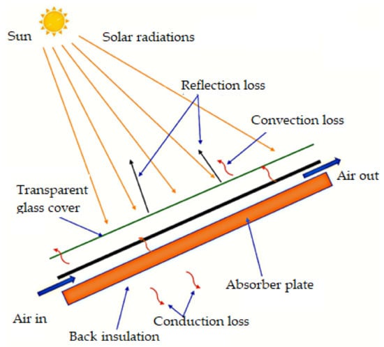
Figure 1.
Component of SAH.
The objective of this review paper is to summarize the works carried out for the performance enfacement of SAH, exploiting the artificial roughness/turbulators of different configurations. Additionally, a performance analysis of various rib configurations is presented to assess the best rib configuration. This study will be helpful to readers who are working in heat transfer enhancement. In the following subsection, the concept of artificial roughness and their corresponding effect are discussed. Additionally, the performance of SAH having artificial roughness is discussed in detail.
2. Performance of SAH
2.1. Heat Transfer Performance
It can be evaluated with the help of an equation proposed by Bliss [2], which is given as:
Further, the efficiency of a SAH is given as:
2.2. Hydraulic Performance
It is totally concerned with pressure drop, which leads to excessive power consumption to run the blower or fan. The pressure drop inside the duct in relation to the friction factor is given as:
The overall performance should be evaluated with the help of various considerations of thermohydraulic performance. The thermohydraulic performance is helpful in the selection of a parameter and solar collector design. The collector should transfer a maximum amount of heat energy with minimum power consumption in the blower. The parameter for augmentation in the thermal performance of a rough duct in comparison with a smooth duct in terms of friction factor and Nu was developed by Lewis et al. [3], called thermohydraulic performance parameter (η), which is given below.
3. Historical Background of Conceptualization of Artificial Roughness in SAH
The SAH is a simple, compact, and economical thermal heating system that has wide applications in so many fields, such as the domestic, industrial, automobile, and agriculture fields. Solar radiations are converted into thermal energy with the help of an absorber plate in the SAH. The flat plate collectors are mainly used in the SAH for distinct heating applications in a wide span. The thermal performance of a SAH is weaker due to a small value of the convection coefficient. This is due to the development of a laminar sublayer adjacent to the absorber plate, which offers thermal resistance to the convection. Therefore, it is imperative to augment the performance of the SAH by adopting a desirable technique of heat transfer augmentation. The convective coefficient can be augmented by installing turbulators on the wall of the duct, which induces turbulence in the flow passage near the absorber plate by disrupting and destabilizing the laminar sublayer. The artificial roughness revivifies the fluid flow pattern adjacent to the absorber plate in the region of a viscous sublayer. The artificial roughness may be in any suitable shape, such as square, rectangular, triangular, conical, spherical, chamfered, or hybrid shape. The roughness geometries used by many researchers are grits, grooves, blockages, baffles, winglets, protrusions, twisted taps, dimples, mesh wires and so on. Alam et al. [1] reviewed distinct arrangements of rib roughness that have been investigated previously, such as V-rib, W-shape rib, chamfered rib, rib with grooves, staggered rib, transverse rib, and discrete rib. The effect of flow due the various rib arrangements is discussed in detail.
The separation and reattachment of flow occur due to roughness in between consecutive roughnesses, which leads to an increment in local wall turbulence, thereby enhancing the convection coefficient. Okamoto et al. [4] analyzed that the value of a local convective coefficient is maximum at the reattachment point as the turbulence intensity is highest just downstream this point. Sparrow et al. [5] showed both experimentally and numerically that the point of reattachment of the flow and position of the maximum convection coefficient is quite close to each other. Cortes and Piacentini [6] developed a performance assessment parameter of the SAH with the help of a numerical model called effective efficiency. They also showed that the effective efficiency of a collector may be enhanced with the help of perturbations. The obstacles also increase air pumping power requirements. Nikuradse [7] studied the turbulent flow of fluids with a distinct degree of relative roughness and developed the temperature and velocity distributions of a sand-grain-roughened pipe for a large span of roughness Re (e+).
Roughness Re is a parameter that combines both the roughness height and Re. Nikuradse [7] identified three regions of fluid flow based on variation in f for a wide span of e+, which are shown in Figure 2.
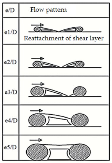
Figure 2.
Flow patterns due to distinct relative rib height [13].
In the hydrodynamically smooth flow region, the value of f for a small range of roughness Re (5 > e+ > 0) is the same for a smooth and rough pipe, and the roughness exists entirely within the laminar sublayer. In the transitionally rough flow region, the magnitude of f increases with the rise in roughness Re as the value of f is a function of roughness Re in this range (70 > e+ > 5). The thickness of the laminar sublayer is the same as the height of the roughness element in this region. Additionally, in the fully rough flow region, the value of f is not depending on the roughness Re in this range (e+ > 70). The friction factor follows the quadratic law of resistance. The height of the roughness extends through the laminar sublayer.
Dipprey and Sabersky [8] developed a wall similarity law that is applicable for both smooth and rough tubes. Webb et al. [9] developed a correlation of heat transfer and f for a repeated rib roughness in case of turbulent flow within the tube. The correlation of heat transfer is based on heat momentum transfer analogy as previously used by Dipprey and Sabersky [8], and friction correlations are based on the wall similarity law as previously used by Nikuradse [7] in the case of the sand grain type of artificial roughness.
The ability of the heat transfer of an artificially rough surface is shown by .
Webb et al. [10] further extended the range of validity of these correlations and proposed that the justified value of e+ is greater than 35. Vilemas and Simonis [11] experimentally investigated friction and convective heat transfer in inner rough tubes for Re numbers 5000 to 500,000. They also developed correlations for friction and heat transfer as given below;
For a fully rough flow condition with rectangular roughness in annular channels:
For a partially rough flow condition with rectangular roughness in annular channels at e/De ≥ 0.0025:
where
The friction factor for channels with rectangular roughness:
Han et al. [12] experimentally investigated the effect of a distinct rib roughness of various shapes, sizes, and cross sections on heat transfer and f. Both St and f have the best value corresponding to p/e = 10. The heat transfer and f correlation are developed based on heat momentum transfer analogy and the wall similarity law, as previously used by Dipprey and Sabersky [8]. They studied four angles of attack between rib roughness and mainstream flow as 20°, 45°, 75°, and 90°. The value of α = 45° has superior convective performance in comparison with others. The correlation for the friction factor:
where,
- a = −0.4 when e+ < 35 and a = 0 when e+ ≥ 35
- b = −0.13 when p/e < 10 and when p/e ≥ 10
The correlation for heat transfer:
where,
- i = 0 when e+ < 35 and i = 0.28 when e+ ≥ 35
- j = 0.5 when α < 45° and j = −0.45 when α ≥ 45°
Prasad and Saini [13] experimentally studied that for specific values of p/e and e/Dh, a geometrically similar roughness has the same effect on the convection coefficient and f. The convective coefficient decreases, and the value of f increases as e/Dh increases. Gupta et al. [14] experimentally investigated that as the relative height of artificial roughness escalates, the optimum flow rate shifts to a lower value. They studied that the Stanton number increases up to Re = 12,000 and decreases after further increment in the value of Re.
4. Effect of Distinct Roughness Parameters
The geometrical parameter of roughness has significant effects on the performance of the SAH. Artificial roughness can be in a distinct shape and size and also in different orientations. According to Lewis [3], the heat transfer and momentum loss function of roughness depend on various parameters of artificial roughness and duct.
The effects of distinct types of rib roughness and various parameters investigated by various researchers are discussed below.
4.1. Effect of Relative Rib Height
The performance of a roughened duct remarkably depends on e/Dh. The value of the friction factor increases, and Nu decreases with the increase in e/Dh. On the other hand, the rate of increase in average Nu decreases with an increase in e/Dh. Prasad and Saini [13] analyzed the effects of e/Dh on the thermohydraulic performance of the SAH. The reattachment occurs only for a small value of e/Dh and does not take place for higher values. The separation and reattachment of flow produced maximum convective heat transfer within a laminar sublayer region. Reattachment occurs only for a small value of e/Dh (Figure 2). Amel Boulemtafes-Boukadoum et al. [15] investigated the performance of the SAH with the help of transverse ribs and also distributed ribs on heat transfer in the upward SAH. They used nondimensional heights of ribs as 66 and 50. The values of e/Dh at which the highest rate of heat transfer was achieved for distinct roughness geometries are shown in Table 1.

Table 1.
Values of e/Dh at which the highest rate of heat transfer for distinct roughness geometries is investigated in the SAH duct.
4.2. Effect of Relative Rib Pitch
The friction factor and Nu enhance with the increase in p/e. For a high rate of heat transfer, p/e should lie between 8 and 10. Prasad and Saini [13] experimentally investigated the effects of p/e on the thermohydraulic performance of the SAH by using the same e/Dh and varying the value of pitch, as shown in Figure 3. The reattachment occurs only when the value of p/e is more than 8. The convection coefficient has the highest values near the reattachment point. The values of p/e at which highest rate of heat transfer was achieved for distinct roughness geometries are shown in Table 2.
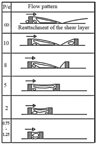
Figure 3.
Flow pattern due to distinct p/e [13].
Table 2.
Values of p/e at which the highest rate of heat transfer for distinct roughness geometries is investigated in the SAH duct.
4.3. Effect of the Cross Section of Rib
The rib cross section has a remarkable impact on thermohydraulic characteristics. Singh et al. [16] studied the performance of the SAH with the help of 3D computational fluid dynamics (CFD) investigations. They studied a roughened duct with an uneven cross-section transvers rib of saw tooth type. This type of roughness shows a higher convection coefficient at Re more than 7000 due to disruption in recirculation. The variation in Nusselt number of surface in comparison with other cross sections w.r.t. to Re is shown in Figure 4. Experiments have been carried to study the thermal performance of five types of ribs that have different cross sections, shapes, and sizes [49]. The sharp cross-sectional rib, such as pentagonal, wedge, square, rectangular, triangular, or trapezoidal, produced radial fluctuating components in the turbulence region. The level of turbulence and reattachment profile is different for different cross sections. The circular or arc-type cross section produces a low level of turbulence because of continuous surface and low-pressure drop.
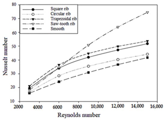
Figure 4.
Nu vs. Re for various cross sections of rib roughness [16].
4.4. Effect of Angle of Attack
The value of α has a remarkable impact on the performance of the SAH. The inclined rib induces a secondary flow in the mainstream along the roughness. Dipprey and Sabersky [8] studied four angles of attack between rib roughness with respect to the stream of flow as 20°, 45°, 75°, and 90°. Among these, α = 45° has superior thermal performance in comparison with others. Taslim et al. [50] experimentally studied the effect of inclined ribs (Figure 5) on the performance of the SAH. The inclined ribs induce vortices just after the application of roughness at the leading edge. After that, it advances along the span of the rib. These vortices increase the turbulence, which results in a high heat transfer rate. They also reported that 45° ribs have the highest thermal performance. A high convection coefficient region occurs at the leading edge, and a low region of convection occurs at the trailing edge. The values of α at which the highest rate of heat transfer was achieved for distinct roughness geometries are shown in Table 3.
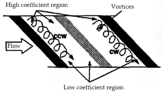
Figure 5.
Vortices due to 45° angled rib [51].
Table 3.
Values of α at which the highest heat transfer rate for distinct geometries of roughness is investigated in the SAH duct.
4.5. Effect of Relative Gaps in Continuous Rib
The performance of the SAH also depends on the gaps between the continuous ribs. The large gap between the continuous ribs retards the flow, and the small gap has less space to flow. The gaps between the continuous ribs, released a secondary flow and mixed with mainstream. The generated vortices and flow pattern of these inclined and discrete ribs are shown in Figure 6. Sahu and Gandhi [52] also numerically studied the thermohydraulic performance of inclined continuous ribs with a gap in the SAH duct. Aharwal et al. [53] further investigated inclined ribs with a c/e of 1.0. This arrangement of roughness shows the highest thermal performance.
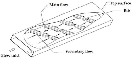
Figure 6.
Flow pattern of inclined discrete–continuous ribs [54].
4.6. Effect of Reynolds Number
The upstream artificial roughness enhances the turbulence level by reducing the reattachment length of the flow. This is due to a decrement in the momentum of flow and mass flux due to which the recirculation zone behind the roughness decreases. The reattachment region shows the highest heat transfer rate in comparison with the region before the reattachment point. Therefore, the reattachment distance from the roughness element decreases as Re increases for a particular boundary layer thickness to a roughness height ratio. The reattachment length varies from 1.4 e to 4 e. The reattachment length strongly depends upon Re up to 8500 and weakly depends on Re above 8500 [55,56].
5. Artificial Roughness/Turbulators
Many researchers have investigated distinct types of artificial roughness arrangements, which have remarkable effects on the performance of the SAH. The distinct artificial arrangement used in different SAH ducts are discussed as follows:
5.1. Transverse Ribs
These ribs disrupt the laminar sublayer and divert the secondary flow towards the sidewall of the duct. Various researchers have studied numerically and experimentally the effect of transverse ribs on the thermohydraulic performance for different rib arrangements. Prasad and Saini [13] studied the effect of a transverse rib on the performance of a SAH for Re ranging from 5000 to 50,000. They used a wire of small diameter as roughness. They reported that as the value of e/Dh increases, convective heat transfer goes on decreasing, and the value of f increases. The f and Nu are augmented 4.25 and 2.38 times, respectively, in comparison with a smooth duct. Gupta et al. [14] also experimentally investigated the thermohydraulic performance at p/e = 10 by using transverse roughness at Re varying from 3000 to 18,000; the aspect ratio of the duct varied from 6.8 to 11.5, and e/Dh = 0.018 to 0.052. The St number increases up to Re = 12,000 and decreases for a higher value of Re. Singh et. al. [57] studied the effect of broken transverse ribs on the performance of the SAH for Re ranging from 3000 to 18,000. They used rib parameters of e/Dh equal to 0.043 and p/e equal to 10. The maximum THPP is 2.10 at Re of 15,000. The highest value of thermal efficiency for smooth ducts and with multiple broken ribs is 44.26% and 72.25%, respectively. Additionally, the maximum effective efficiency is 44.25% and 69.15%, respectively. Prasad and Mullick [58] studied the effect of a small-diameter wire as roughness in transverse direction to the direction of the flow. The protruding wires as a roughness element augment the convection coefficient. The collector efficiency factor increases from 0.68 to 0.72 corresponding to the enhancement in thermohydraulic performance equal to 14% at Re = 40,000.
Karwa et al. [59] studied the effect of repeated chamfered ribs (Figure 7) on the performance of a SAH at Re ranging from 3750 to 16,350. They applied artificial roughness in transverse direction to the flow from one sidewall to the other end of the duct. Nu and the friction factor enhanced from 50% to 120% and 80% to 290%, respectively. The thermal efficiency of the SAH increased from 10% to 40%. Verma and Prasad [60] experimentally investigated the thermohydraulic performance of a SAH by using small-diameter wires as roughness elements in the transverse direction with p/e values varying from 10 to 40 and e/Dh values from 001 to 0.03 at Re values of 5000 to 20,000. The value of e+ varied from 8 to 42. They obtained an optimum performance of 71% at e+ value of 24. Sahu and Bhagoria [20] studied the effects of a transverse broken rib (Figure 8) on the thermohydraulic performance of the SAH with e/Dh = 0.0338 and a p/e range of 10–30. The height of the roughness was 15 mm, and values of Re = 3000–12,000. They reported that the value of Nu is the maximum for p/e = 20 and also studied that the smooth duct shows better thermal performance at low Re (i.e., below 5000 in comparison with a roughened duct). The heat transfer was augmented in the range of 1.25 to 1.40.
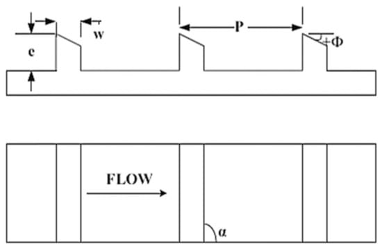
Figure 7.
Chamfered transverse rib roughness [61].
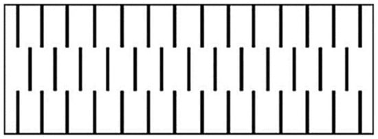
Figure 8.
Transverse broken ribs [54].
Behura et al. [62] investigated the effects of a three-side transverse type of roughness on the thermohydraulic performance of the SAH by using a wire with 20, 22, and 24 SWG dimensions at Re ranging from 5000 to 13,000. The heat transfer factor increased by 0.3% to 0.4%.
5.2. Inclined Ribs
Various researchers numerically and experimentally studied the effect of an inclined rib on thermohydraulic performance with respect to the flow of air and the arrangement of a rib attachment. Gupta et al. [23] analyzed the effect of incline repeated ribs of circular cross section (Figure 9) on the performance of the SAH. The value of p/e was fixed at 10, Re ranged from 3000 to 19,000, and the value of e/Dh ranged from 0.023 to 0.050. The thermal efficiency was enhanced 1.16 to 1.25 times over the smooth duct. Aharwal et al. [63] studied the effect of a square cross-section inclined repeated rib with gaps (Figure 10) on the SAH for the value of e/Dh equal to 0.0337, α equal to 60°, and p/e equal to 10 at Re ranging from 3000 to 18,000. The gap in inclined ribs generates a secondary flow, which creates extra turbulence and thermal performance. The friction factor and Nu were augmented up to 2.87 and 2.59 times, respectively, over the smooth duct. Further, Aharwal et al. [17] analyzed the performance by varying different parameters, such as e/Dh, α, p/e, and the relative gap position. The e/Dh, p/e, and α varied from 4 to 10, 0.018 to 0.0337, and 30° to 90°, respectively. The f and Nu were augmented up to 3.6 and 2.83 times, respectively, over the smooth duct for e/Dh = 0.037, gap position = 0.25, and a gap width of 1. The flow over inclined ribs is shown in Figure 11. Lu and Jiang [64] experimentally investigated the effect of an inclined rib at α = 45° on the performance of the SAH in a rectangular duct. Further, they numerically investigated the thermohydraulic performance of an inclined rib with inclination angles as 0°, 10°, 20°, 30°, 45°, 60°, and 90°. The 60° inclined rib showed the highest convective heat transfer, and the 20° inclined rib showed the best thermohydraulic performance.
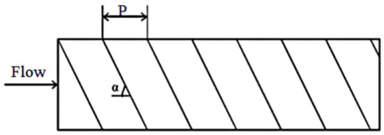
Figure 9.
Inclined repeated ribs [65].
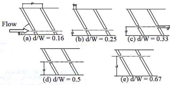
Figure 10.
Inclined continuous repeated ribs with a gap [17].
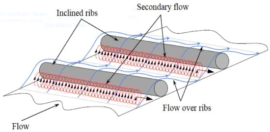
Figure 11.
Flow over inclined ribs [66].
5.3. V-Shaped Ribs
Various researchers have experimentally and numerically investigated the effect of a V-shaped rib on thermohydraulic performance with respect to the flow and distinct attachment arrangement of roughness. Momin et al. [24] studied the effect of various geometric parameters of V-shaped artificial rib roughness (Figure 12) on the thermohydraulic performance of a rectangular duct at Re ranging from 2500 to 18,000. The p/e remained fixed at 10, e/Dh varied from 0.02 to 0.034, and α varied from 30 to 90°. The friction factor and Nu decreased and increased, respectively, with an increase in Re. The highest augmentation in the friction factor and Nu was found at α = 60° at 2.83 and 2.30 times, respectively, in comparison with a smooth duct. V-shape ribs are advantageous in comparison with inclined ribs. They show a value of Nu 1.14 times more at a Re value of 17,034 in comparison with inclined ribs.
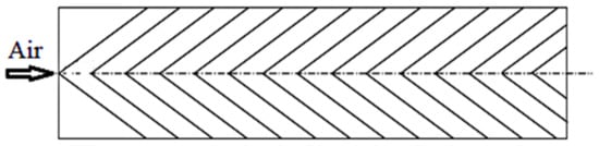
Figure 12.
V-shaped type of rib roughness [24].
Singh et al. [19,67] analyzed the performance of a roughened duct by using a V-shaped down discrete rib (Figure 13) type of roughness. The experimental parameters Re, e/Dh, p/e, α, g/e, and d/x varied in the range of 3000–15,000, 4–12, 0.015–0.043, 30°–75°, 0.5–2.0, and 0.20–0.80, respectively. The highest augmentation in friction factor Nu was 3.11 and 3.04 times over the smooth duct, which occurred at α equal to 60°. The highest value of THPP was 2.06. The effective efficiency was enhanced up to 91% as that of the SAH with a smooth duct. According to Alam et al. [51], the geometrical parameter of roughness has significant effects on the thermohydraulic performance of the SAH. Singh et al. [68] further investigated the effect of a V-shaped down rib with a gap on the performance of the SAH. The highest values of f and Nu were achieved at p/e = 8. The value of THPP ranged from 1.27 to 1.93. Karwa et al. [45,69] analyzed the effect of a repeated rib in a rectangular cross-section V-discontinuous and V-discrete arrangement. The relative roughness length and α varied from 3 to 6 and 45° to 60°, respectively. The discrete V-shaped ribs with α = 60° showed better performance in comparison with discrete V-shaped ribs with α = 45°. The V-down arrangement of ribs showed better performance in comparison with the V-up pattern. Hans et al. [28] also studied the effect of a continuous multi-V-rib shown in Figure 14. Maithani and Saini [25] analyzed effect of a V-shaped rib with multiple symmetrical gaps (Figure 15) on the thermohydraulic performance of the SAH. The thermohydraulic performance of the SAH was studied for Re 18,000, whereas p/e varied from 6 to 12 with symmetrical gaps in one limb of V-rib varying from 1–5, g/e varied from 1–5, and α varied from 30° to 75°, however, e/Dh is kept fixed at 0.043. The thermohydraulic performance of the SAH strongly depends on the number of symmetrical gaps and g/e in the limbs. The f and Nu was augmented 3.67 and 3.6 times, respectively. The highest value of Nu is achieved at three symmetrical gaps and further, incremented in the number of gaps, degrading the thermal performance. The value of Nu increased up to g/e equal to 4 and thereafter decreased. Deo et al. [26] analyzed the effect of a multigap V-shaped down-rib combined with a staggered rib (Figure 16) on the performance of the SAH.
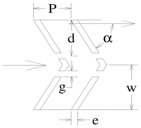
Figure 13.
V-down discrete rib [19].
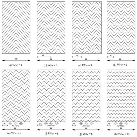
Figure 14.
Multi-V-rib roughness [28].
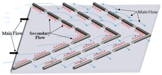
Figure 15.
V-shaped rib with multiple symmetrical gaps [25].
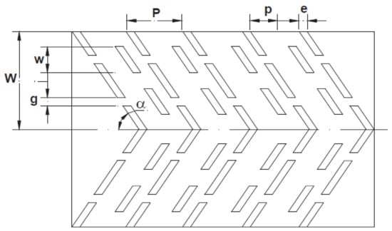
Figure 16.
Multiple-gap V-shapes down-rib combined with a staggered rib [26].
The experimental parameter ranges were Re = 4000–12,000; α = 40°–80°, and p/e = 4–14. The parameters w/e = 4.5 and g/e = 1 were fixed. The maximum increments in THPP and Nu were 2.45 and 3.34 times, respectively, over the smooth duct. The best value of THPP was achieved near a Re of 12,000. Patil et al. [27] analyzed the effect of V-shaped broken ribs combined with a staggered rib (Figure 17) on the performance of the SAH. The studies encompassed parameter ranges of Re = 3000–17,000; p’/p = 0.2–0.8; and r/e = 1–2.5 for a fixed value of e/Dh = 0.043, g/e = 1, α = 60°, and p/e = 10. The highest augmentation in Nu was found up to 3.18 times over the smooth duct. Jain and Lanjewar [70] analyzed the thermohydraulic performance of the SAH by using a V-shaped rib with symmetrical gaps combined with staggered ribs. The parameters p/e and Re varied from 10 to 16 and 3000 to 14,000, respectively, for a fixed value of p’/p = 0.65, α = 60°, and r/e = 4. The highest augmentations in the friction factor and Nu were 3.13 and 2.30, respectively, for p/e = 12.
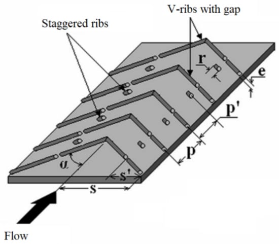
Figure 17.
V-shaped broken rib combined with staggered ribs [82].
Kumar and Kim [71,72] studied the effect of various ribs in V-form on the performance of the SAH in the Re range of 5000–20,000. The various V-form ribs include V-rib. They used parameter values of α = 60° and e/Dh = 0.040. They reported that a V-shaped rib combined with grooves shows the highest value of THPP as that of other investigated V-ribs of different arrangements. Nidhul et al. [73] used CFD and exergy analysis to study the effect of a secondary flow in the duct generated due to a V-shaped rib on the thermohydraulic performance of an SAH duct. Re ranged from 5000 to 20,000. The value of e/Dh = 0.05, and p/e = 10. The reported value of the highest augmentation in Nu was 2.41 times over the smooth surface at Re = 7500 and α = 45°, and the maximum value of f was 2.53 times over the smooth surface at Re = 17,500 and α = 60°. Mishra et al. [74] used CFD analysis for a V-shaped down rib with multigap and turbulence promoters (Figure 18) to study the performance of a triangular-duct SAH in the Re range of 4000–20,000. The investigation covered an α range of 45° to 60° and a p/e range of 8 to 14. The maximum thermal performance was achieved at p/e = 10 and α = 45°. The THPP increased as Re increased from 4000 to 10,000, then thereafter decreased in the upper range of Re. Patel and Lanjewar [75] experimentally and numerically studied the effect of novel V-shaped ribs on the performance of the SAH. The study parameter varied as p/e = 6–14 whereas other parameters viz. p’/p = 4, r/e = 4, g/e = 4, α = 60°, e/Dh = 0.043 and Ng = 3 with Reynolds number in the range of 4000 to 14,500. The highest augmentation took place in Nu = 1.55 to 2.26 and the friction factor = 2.63 to 3.40 at p/e equaling 10 and 8, respectively, in comparison with a smooth surface. The highest value of THPP = 1.59 was achieved at p/e = 10 and Re = 12,364. Further, Patel and Lanjewar [76] analyzed the effect of a V-shaped roughness geometry with staggered elements using additional gaps in symmetrically arranged elements of roughness (Figure 19) on the performance of the SAH. The distinct experimental parameters varied as e/Dh equaled 0.043, g/e equaled 4, p/e equaled 10, p′/p equaled 0.4, Ng equaled 4, d/w equaled 0.25 to 0.85, and Re equaled 4000–15,000. The highest value of the THPP parameter was 1.82 at d/w equaling 0.65 and Re = 12,524. Alam et al. [77,78,79,80] experimentally analyzed the effect of V-shaped perforated blocks (Figure 20) on the performance of the SAH. The study encompassed parameter ranges of e/H = 0.4 to 1.0, p/e = 4 to 12, α = 60°, and Re = 2000 to 20,000. The highest augmentations in Nu and f were 6.76 and 28.84 over the smooth duct at e/H = 0.8 and p/e = 8. Further, Alam et al. [81] experimentally studied the effects of different types of perforation shapes on the performance of the SAH. They used square, rectangular, and circular types of perforation shapes in a 1–0.6 range of circularity. The value of α varied from 30° to 75°. The highest values of Nu and f were achieved at α = 60°. The noncircular shapes of perforation showed a higher thermal performance than that of circular shapes.
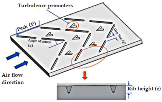
Figure 18.
V-shaped rib with multiple gaps and turbulators [74].
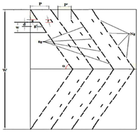
Figure 19.
V-shaped roughness geometry with staggered elements [76].
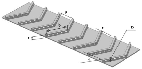
Figure 20.
V-shaped perforated blocks [80].
5.4. Multi-V-Shaped Ribs
Singh et al. [83] analyzed effect of a multi-V-rib with multi uniform gaps on the performance of the SAH. The friction factor and Nu were augmented 5.67 and 6.46 times in comparison with a smooth duct at e/w = 0.866, x/w = 0.25, W/w = 6, and e/Dh = 0.0454. The highest value of THPP equaling 4.24 was achieved. Kumar et al. [29] investigated the effect of a multi-V-shaped rib with gaps on the performance of a rectangular duct in a SAH, as shown in Figure 21. The ranges of various parameters were Re varying from 2000 to 20,000 and g/e = 0.5–1.5. The fixed value of α = 60°, e/Dh = 0.043, and p/e = 10. The friction factor and Nu were augmented 6.13 and 6.32 times, respectively, in comparison with a smooth duct. The best value of THPP was achieved at g/e = 1 and d/x = 0.69. Further, Kumar et al. [84,85] studied the performance of this artificial roughness with the parameter’s W/w = 6, W/e = 12, e/Dh = 0.0433, and g/e = 1.0. The value of α ranged from 30° to 75°. They reported that f and Nu are strong functions of α, and also, they have a maximum value at α = 60°. Jin et al. [86,87,88] numerically analyzed the effect of an inline and staggered multi-V-shaped rib on the performance of the SAH. The staggered arrangement had highest enhancement of 26% and 18% in Nu and THPP, respectively, over the inline arrangement of ribs. The maximum value of THPP was 2.43. Promvonge and Skullon [89] studied the effect of V-shaped flap-baffle and chamfered-grove vortex generators (VG) on the performance of a roughened duct, as shown in Figure 22. Both the flap baffle and VG were at α equal to 45°, and the experiment was performed in both the apex-up and apex-down pattern of a V-shaped flap baffle in the range of Re = 5290–22,600. The apex-up pattern had better performance in comparison with the apex-down pattern of V-shaped flap baffles. Nu and the friction factor were enhanced remarkably by using this type of roughness. They reported that the maximum value of TEF was 2.68 at Re = 5290.
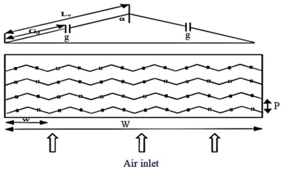
Figure 21.
Multi-V-shaped rib with gap [29].
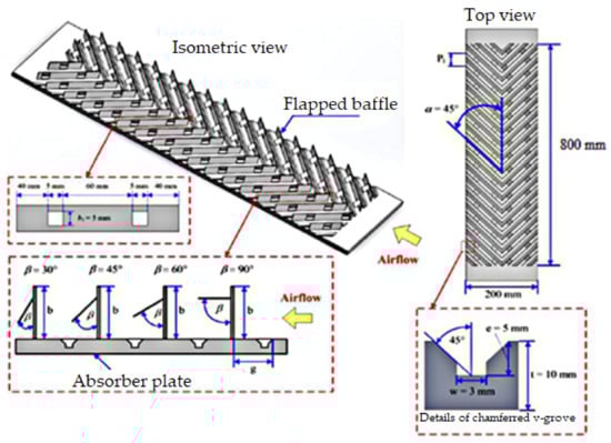
Figure 22.
V-shaped flap-baffle and chamfered-grove vortex generators [89].
5.5. Arc-Shaped Ribs
Various researchers have numerically and experimentally investigated effect of arc-shaped ribs on performance with respect to the flowing fluid and pattern of ribs on the duct surface. Yadav et al. [32] studied the effect of a circular protrusion that is in an angular arc pattern (Figure 23) for various parameters varying as p/e equal to 12–24 and α’ equal to 45°–75° and re varying from 3600 to 18,100. The highest increments in f and Nu were reported to be 2.93 and 2.89 times, respectively, for p/e = 12 and e/Dh = 0.03. Sahu and Prasad et al. [90] investigated effect of an arc-shaped wire type of roughness on the performance of the SAH by using exergy efficiency analysis, as shown in Figure 24. The maximum augmentation in the exergetic efficiency corresponding to e/Dh equaled 0.0422, which was 56% as that of the smooth-plate SAH. The exergetic efficiency strongly depends on the various roughness parameters and Re. Gill et al. [91,92] investigated the effect of a broken-arc rib combined with staggered rib pieces on the performance of the SAH. The experimental parameters encompassed r/g = 1 to 6, α/90 = 0.333, p’/p = 0.4, W1/w = 0.65, e/Dh = 0.043, and Re = 2000 to 16,000. The f and Nu were augmented 2.50 and 3.06 times as that of the smooth duct and 2.77 and 2.60 times over the broken-arc-type-rib roughened duct. The highest value of THPP was achieved at r/g = 4. On the same type of roughness, Hans et al. [33] further studied the effect of broken-arc-shaped artificial roughness (Figure 25) on the thermohydraulic performance of the SAH. The study encompassed parameters of p/e equal to 4–12, g/e equal to 0.5–2.5, e/Dh equal to 0.022–0.043, d/x equal to 0.2–0.8, α’ equal to 15°–75°, and Re varying from 2000 to 16,000.
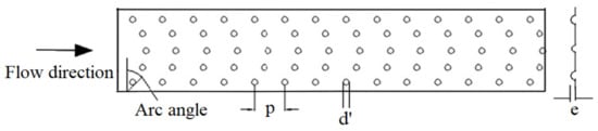
Figure 23.
Arc-shaped protrusions as artificial roughness [32].
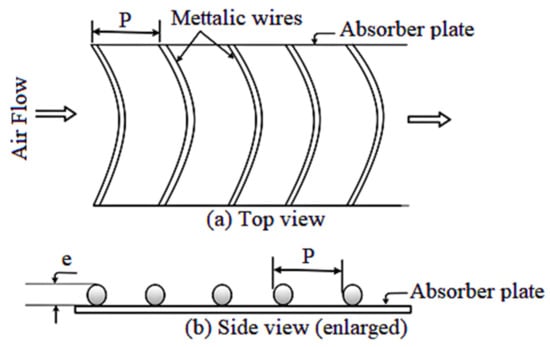
Figure 24.
Arc-shaped artificial roughness [90].
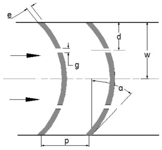
Figure 25.
Brocken-arc-shaped roughness [33].
The augmentations in f and Nu were reported to be 2.44 and 2.63 times as that of the smooth duct. The corresponding values over the continuous arc-shaped rib were 1.19 and 1.14 times, respectively. Ghritlahre et al. [93] studied the performance of an arc-shaped artificially roughened duct with an apex-down and apex-up flow of air. They took a values of p/e equal to 10, arc angle = 60°, and e/Dh = 0.0395. The highest efficiency of the apex-up pattern was achieved at 73.2%, and for the apex-down pattern, it was 69.2%. The apex-up pattern performed 33.2% better in comparison with the apex-down arrangement. The thermal performance of the apex-up pattern was better as compared with the apex-down pattern of an arc-shaped artificially roughened duct. Yadav and Prasad [94] theoretically studied the effect of arc-shaped wire roughness on the performance of a parallel-flow SAH. The thermal efficiency of a roughened parallel-flow SAH was 8% to 10% higher in comparison with a smooth SAH. Ambade and Lanjewar [95] experimentally studied the effect of a symmetrical gap with arc-shaped roughness and a staggered element on the performance of the SAH at Re equal to 3000–15,000 and p/e equal to 6–14. The fixed parameters were p’/p = 3, g/e = 4, r/e equal to 4, Ng equal to 3, and α’ equal to 30°. They compared this geometry with the smooth duct and the duct having broken-arc-shaped rib roughness with staggered elements. The arc-shaped roughness with a new symmetrical gap augmented the friction factor and Nu up to 4.15 and 2.04 times, respectively, over the broken-arc-shaped roughness with a staggered element, while augmentation in Nusselt number and friction factor were 2.18 and 3.88 times, respectively with corresponding smooth duct. Azad et al. [96] investigated the effect of a discrete-symmetrical arc type of rib roughness on the performance of the SAH. The values of the experimental parameters covered in the study were e/Dh = 0.045, g/e = 2–5, Ng = 3, p/e = 10, α’ = 30°, and Re = 3000 to 14,000. The value of g/e had a remarkable effect on the performance. The highest enhancement reported in Nu was equal to 3.88 over the smooth duct at g/e = 4. The value of THPP ranged from 1.4 to 1.68 at g/e = 4, and the best value of THPP was 1.68 at Re equal to 14,000. Gill et al. [97] analyzed the effect of staggered broken-arc hybrid-rib roughness on the thermohydraulic performance of the SAH. The parameters of the study ranged as e/Dh = 0.022–0.043, α’ = 15–75°, p/e = 4–12, and Re = 2000–16,000. The f and Nu were augmented 2.57 and 3.16 times over the broken-arc roughened duct. The highest value of THPP was reported to be 2.33. Sureandhar et al. [98] studied the effect of arc-rib fin-type roughness on the performance of the SAH. The experimental parameters of the study varied as e/Dh = 0.04222–0.0541, α/90 = 0.3333, and p/e = 10. Nu and THPP increased as the mass flow rate increased, while the friction factor decreased.
5.6. Multi-Arc-Shaped Ribs
Various researchers numerically and experimentally analyzed the effect of a multi-arc-shaped rib on thermohydraulic performance with respect to the flowing fluid and attachment arrangement of roughness on the duct surface. Kumar et al. [99] experimentally analyzed the effect of a discrete arc-shaped rib on the performance of the SAH. The ranges of the parameters in the study were g/e = 0.5–1.5, number of gaps = 1–3, and d/x = 0.3–0.9. The optimum value of THPP was equal to 3.85 achieved at W/w = 1, d/x = 0.6, and number of gaps = 3. Saravankumar et al. [100] investigated the effect of arc-shaped ribs with fins and baffles on the performance of the SAH. They reported that the exergy and effective efficiency were augmented by 28.3% and 27.1%, respectively, in comparison with the SAH duct with an arc-shaped rib. Further, Saravankumar et al. [101] studied the exergetic performance of the SAH duct with arc-shaped roughness with fins and baffles. They reported the exergy efficiency to be equal to 5.2% in the optimum conditions. Agrawal and Bhagoria [102] experimentally investigated the effect of a discrete type of roughness without a gap in a double-reverse arc pattern on the thermohydraulic performance of the SAH. They considered experimental parameters of, first, p/e = 6.67 to 11.67 and α’ = 60°, and after that, p/e = 8.33 and α’ = 30° to 75°. They reported the highest augmentation value of Nu = 134.63 at α’ = 60°, e/Dh = 0.027, and Re = 3010. The friction factor at α’ = 60°, e/Dh = 0.027, and Re = 3010 was 0.0342. Hassan et al. [103] studied the effect of a multiarc dimple-shaped roughness (Figure 26) on the performance of the SAH. They covered experimental parameters of p/e equal to 4–16, W/w equal to 1–5, e/Dh equal to 0.018–0.036, α’ equal to 30°–75°, and Re equal to 2000–18,000. They reported that the highest value of Nu was 3.19 to 5.56 times that of the smooth duct at p/e equal to 12. The value of Nu increased up to e/Dh equal to 0.036; after that, it decreased. The enhancement in the friction factor equaled 1.36 to 2.27 times in comparison with the smooth duct at e/Dh equal to 0.045. Agrawal et al. [104] experimentally investigated the effect of a double-arc reverse rib with even gaps on the performance of a solar collector. The values of the fixed parameters were e/Dh = 0.027, W/H = 8, and I = 1000 W/m2. The value of the variable parameter varied as p/e equal to 10, α equal to 30°–75°, and Re equal to 3000–14,000. The maximum augmentations in f and Nu were found to be 2.42 and 2.85 times over the smooth surface. The highest value of THPP equal to 2.41 was noticed at p/e = 10 and e/Dh = 0.0270.
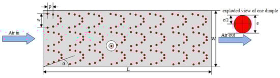
Figure 26.
Multiarc dimple-shaped roughness [103].
5.7. W-Shaped Ribs
Various researchers numerically and experimentally analyzed the effect of W-shaped ribs on performance with respect to the flow of air and the attachment pattern of a rib on the surface an SAH duct. Lanjewar et al. [36] studied the performance of a SAH duct with a W-shaped rib type of roughness in both a W-down and W-up pattern of the artificial roughness. The values of various parameters taken were e/Dh equal to 0.03375, Re range of 2300–14,000, and p/e equal to 10. The ranges of THPP were 1.21 to 1.73 and 1.46 to 1.95, respectively, for top-up and top-down patterns. The W-down pattern of artificial roughness had better performance in comparison with the W-up pattern. Kumar et al. [38] studied the effects of a discrete-W-shaped rib (Figure 27) on the performance of the SAH in the Re range of 3000 to 15,000. The value of the parameter p/e was fixed at 10, e/Dh varied from 0.0168 to 0.0338, and α varied from 30° to 75° during the experiment. The highest augmentations in the friction factor and Nu were found to be 2.75 and 2.16 at e/Dh = 0.0338 and α = 60°. Kumar et al. [105] investigated the effect of W-shaped ribs with a booster mirror on the performance of the SAH. The combination of W-shaped roughness with a booster mirror enhanced Nu, St, and the friction factor by 29–38%, 31–39%, and 23–29% in comparison with that without a booster mirror.
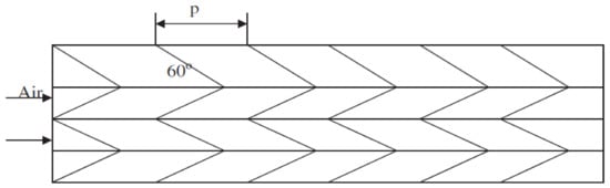
Figure 27.
W-shaped artificial roughness [106].
5.8. L-Shaped Ribs
Gawande et al. [39] studied the effect of reverse L-shaped repeated rib artificial roughness on the convective performance of the SAH through experimentation and CFD analysis, as shown in Figure 28. The effect of L-shaped roughness was studied in the ranges of parameters of p/e = 7.14–17.86 and Re = 3800–18,000; however, the value of e/Dh was fixed at 0.042. The highest enhancement in Nu was found up to 2.827 times as that of the smooth duct at p/e = 7.14 and Re = 15,000. The highest augmentation in the friction factor was found up to 3.424 times over the smooth duct at e/Dh = 0.042, Re = 3800, and p/e = 7.14. THPP was found to be in the range of 1.92 to 1.90 by using this repeated roughness.
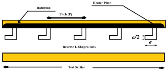
Figure 28.
L-shaped artificial roughness [39].
5.9. S-Shaped Ribs
Kumar et al. [40] studied the effect of an arc-shaped wire rib arranged in an ‘S’ type of pattern (Figure 29) on the performance of the SAH. The study considered various parameter ranges of e/Dh = 0.022–0.054, p/e = 4–16, W/w = 1–4, α = 30°–75°, and Re = 2400–20,000. The utilization of arc-shaped roughness in an ‘S’ type of pattern augmented the friction factor and Nu 2.71 and 4.64 times, respectively, in comparison with a smooth duct at the parameter’s p/e, W/w, and α at 8, 3, and 60° respectively. Wang et al. [107] analyzed the effect of an S-shaped rib with gaps (Figure 30) on the performance of the SAH. The various parameters varied as Re = 2000 to 20,000, p/e = 20 to 30, e/Dh = 0.023 to 0.036, W/w = 3 to 5, and g/e = 1 to 2. The highest increase in Nu was found 5.42 times as that of the smooth duct at the parameters p/e = 20, W/w = 4, and Re = 19,258. The highest increase in f was 5.87 times over the smooth duct.
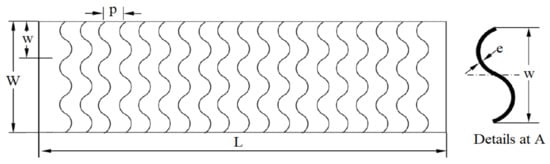
Figure 29.
Arc-shaped wire ribs arranged in an ‘S’ type of pattern [40].
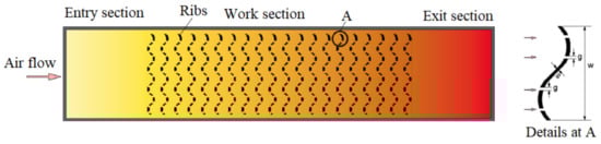
Figure 30.
S-shaped ribs with gaps [107].
5.10. Delta Winglet-Shaped Ribs
Baissi et al. [108] studied the effect of a longitudinally curved delta-shaped vortex generator with perforation and without perforation type of roughness on the performance of the SAH. The experimental parameters covered a range of parameters as Re = 2500–12,000, e/Dh = 0.8, and α = 45°. The friction factor and Nu were augmented 45.83 and 6.94 times in comparison with a smooth duct. The best value of TEF was equal to 2.26 at Re = 11,382. Kumar and Layek [109,110] analyzed the performance of a SAH duct with the help of winglet types of vortex generators (Figure 31). The experimental parameters covered the ranges of parameters as p/e = 5–12, α = 30°–75°, W/w = 3–7, and Re = 3000–22,000. The optimum value of Nu was achieved at α = 60° and p/e = 8. Kumar et al. [111] analyzed the performance of the SAH by using delta-shaped winglets with perforation. The thermohydraulic performance had a maximum value of 3.14 at Re = 12,000 and with a zero spacer length. The f and Nu were augmented 4.52 and 5.17 times, respectively, as that of the smooth duct. Promvonge et al. [112] analyzed the effect of a punched delta-shaped winglet type of roughness in the duct of the SAH. The experimental parameters covered the ranges of parameters as PR varying from 1 to 2, dR varying from 0 to 0.583, Re varying from 4000 to 24,000, and angle of attack equal to 30°. Nu was enhanced in the range of 17.1 to 78.21, and the friction factor was augmented in the range of 3.92 to 5.9 in comparison with a smooth duct.
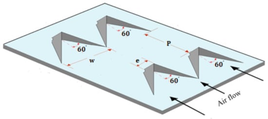
Figure 31.
Winglet types of vortex generator [109].
5.11. Quarter Circular-Shaped Ribs
Mahanand and Senapati [113] numerically studied the performance of the SAH by using quarter circular-shaped ribs. The p/e varied from 7.14–17.86, Re varied from 3800 to 38,000 and e/Dh = 0.042. Nu and f were augmented 2.7816 and 3.4355 times at Re equal to 15,000 and 3800 and p/e equal to 7.14, respectively. The thermal augmentation ratio had a maximum value of 1.88 at e/Dh equal to 0.042, Re equal to 15,000, and p/e equal to 7.14.
5.12. Dimple/Protrusion-Shaped Roughness
Bhushan and Singh [41] studied the effect of a protrusion type of roughness (Figure 32) on the performance of the SAH. The study parameters encompassed S/e = 18.75 to 37.50, L/e = 25.00 to 37.50, e/Dh = 0.03, W/H = 10, d’/D = 0.147–0.367, and Re = 4000 to 20,000. The protruded duct surface had a higher value of convection coefficient in comparison with a smooth duct. The highest values of f and Nu were 2.2 and 3.8 times as that of the smooth duct. The highest augmentation in convection coefficient occurred at L/e = 31.25 and d/D = 0. 294. Gilani et al. [114] experimentally investigated the effect of pin-type protrusions of conical shape on the performance of the SAH. The staggered arrangement pattern of protrusion was much more effective compared with the inline pattern arrangement by up to 15% at Ra = 50,000 to 75,000. They tested three types of conical pin protrusions of 2, 3, and 4-mm height. The experiment was performed at pith values of 16, 32, and 48 mm. The highest value of Nu was achieved at p = 16 mm, and the efficiency was enhanced by 26.5% at this pith value. Perwez and Kumar [115] analyzed the thermal performance of the SAH with spherical dimple-shaped roughness at the absorber plate at Re varying from 1900 to 6000. The maximum value of convection coefficient was 20.23 W/m2K, and the instantaneous thermal efficiency was 23.45–35.50% higher in comparison with a smooth duct.
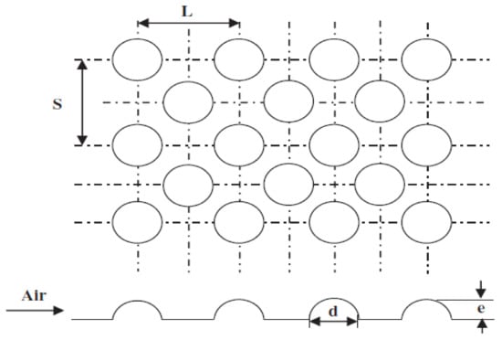
Figure 32.
Protrusion-type roughness [41].
5.13. Pentagonal Shape Ribs
Debnath et al. [116] analyzed the thermal performance of pentagonal rib roughness on the performance of a SAH duct with the help of a CFD code. The values of various investigation parameters were taken as Re = 12,633–62,842, e/Dh = 0.045–0.084, and p/e = 6.43–8. The optimum configurations of various parameters were found as e/Dh equal to 0.045 and Re equal to 38,414. The augmentations in the friction factor and Nu at optimum configuration were 67.2% and 70%, respectively, over the smooth duct.
5.14. Stepped Cylinder Ribs
Antony et al. [117] numerically analyzed the effect of stepped-cylinder-rib-type roughness on the performance of the SAH in the Re range of 3000 to 24,000. The core diameter of the artificial roughness varied from 3 mm to 7 mm with a step of 1 mm. The experimental parameters encompassed the range of parameters as p/e = 11.11–27.78 and number of steps in the roughness varying from 1 to 3. The maximum augmentation in Nu number was found to be 76.41 at Re = 24,000. A TEP and THPP of 1.14 and 1.49 were achieved at Re of 15,000 and 18,000, respectively.
5.15. NACA Profile Ribs
Patel et al. [118] analyzed the effect of reverse NACA 0040 type of profile rib on the performance of the SAH in the Re range of 6000 to 18,000. a THPP of 2.53 was achieved at Re = 6000. A maximum value of Nu of 104.45 was achieved at Re = 18,000.
5.16. C-Type Rib Roughness
Gabhane and Kanase-Patil [119] analyzed the effect of multi-C-type rib roughness (Figure 33) on the performance of the SAH. The experimental parameters covered the ranges of parameters as p/e = 8 to 40, Re = 3000 to 15,000, and α = 30° to 60°. The values of rib height, duct aspect ratio, and e/Dh were 2 mm, 10, and 0.02, respectively. The highest value of Nu was found to be 415 at Re = 15,000 and p/e = 24. The value of THPP was equal to 3.48. Saravanan et al. [120] studied the effect of the staggered multi-C-shape finned surface of the absorber on the performance of the SAH. They investigated both perforated and nonperforated surfaces of the absorber. The experimental parameters varied as p/g = 3.4–3.8 and Re = 3000–27,000. The secondary flow generated along the surface of the fin and the mixing of the secondary flow developed in the duct with the mainstream of flow enhanced the level of turbulence remarkably. In the case of perforated surface, the friction factor Nu was augmented 5.34 and 2.67 times as that of the smooth duct at p/g = 3.8. In the case of a nonperforated surface, the friction factor and Nu were augmented 5.93 and 2.61 times over the smooth duct.
Figure 33.
Multi-C-type rib roughness [119].
5.17. Twisted Tapes
Kumar and Layek [121,122] analyzed the effects of twisted ribs on the performance of the SAH for Re of 3500 to 21,000. The experimental parameter varied as α = 30–90°, p/e = 6–10, and y/e = 3 to 7. The highest augmentations in f and Nu were 1.78 and 2.58 times over the smooth duct. Further, Kumar and Layek [123] also performed numerical analysis for optimizing the exergetic efficiency and energetic efficiency by using the same type of rib roughness. The highest augmentation ineffective efficiency, thermal efficiency, and exergetic efficiency were equal to 1.79, 1.81, and 1.81 times over the smooth duct at a twist ratio equal to 3 and p/e = 8.
5.18. Hyperbolic-Shaped Ribs
Thakur et al. [124] analyzed the performance of the SAH by using hyperbolic-shaped (Figure 34) artificial roughness with the help of a CFD code. They analyzed the performance in the parameter range of p equal to 10 to 20 mm and e equal to 0.5 to 2 mm. The best performance of the SAH was achieved at e = 1 mm, p = 10 mm, and Re = 6000.
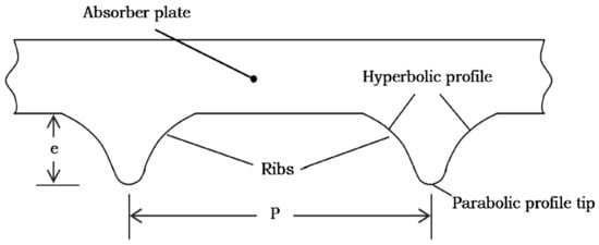
Figure 34.
Hyperbolic-shaped ribs [124].
5.19. Wedge-Shaped Rib
Bhagoria et al. [46] investigated the effect of wedge-shaped ribs (Figure 35) in transverse arrangement on the performance of the SAH. The experimental parameter ranged as e/Dh = 0.015–0.033, Re = 3000–18,000, p/e = 60.17ϕ−1.0264 < p/e < 12.12, and α = 8°–15°. The friction factor and Nu were augmented 5.3 and 2.4 times, respectively. The highest heat transfer performance was achieved at ϕ about 10° and p/e = 7.57. Nu decreased on both sides of this wedge angle.
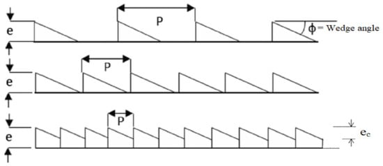
Figure 35.
Wedge-shaped roughness [46].
5.20. Spherical-Ball-Type Roughness
Manjunath et al. [15] numerically investigated the effect of spherical turbulators (Figure 36) on the performance of the SAH. The study parameter encompassed a turbulator diameter varying from 5 to 25 mm, Re ranging from 4000 to 25,000, and p/e varying from 3 to 12. The thermal efficiency increased as the value of p/e decreased and also as the diameter of the sphere increased. The maximum value of Nu was equal to 2.5 times as compared with the smooth duct at p/e = 3 and Re = 23,560. The thermal efficiency increased up to 23.4% over the smooth surface. Kumar and Murmu [125,126] experimentally studied the effect of a spherical ball type of roughness in an inclined pattern (Figure 37) on the performance of a roughened duct. The experimental parameter varied as p/e = 9 to 18, α = 35 to 75°, e/db = 0.5 to 2, and Re = 2500 to 18,500. They reported that the highest thermal efficiency achieved was 81.30% at α = 55°, e/db = 1, and p/e = 15. The lowest thermal efficiency was achieved at p/e = 9.
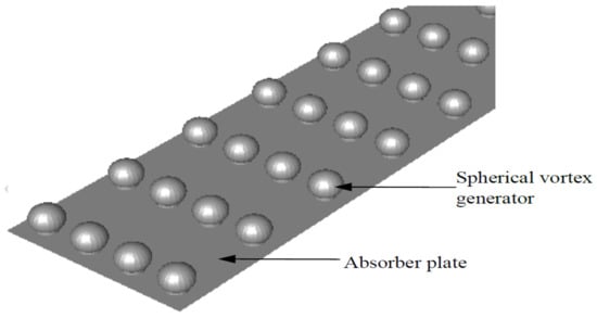
Figure 36.
Spherical turbulators [125].
Figure 37.
Spherical ball type of roughness in an inclined pattern [126].
5.21. Combination of Different Types of Ribs
Promvonge et al. [127] investigated the effect of a V-shaped rib and delta groove on the performance of the SAH. Re ranged from 7000 to 30,000, and α was equal to 60°. The highest value of thermal performance was achieved at e/H = 0.108 and p/H = 1.0. Sharma and Kalamkar [128] experimentally and numerically studied the effects of distinct arrangements of ribs on the performance of the SAH. For one pitch length, two truncated and two thin-transverse-continuous ribs were used. The study parameters encompassed e/H = 0.1, e/Dh = 0.055, α = 90°, Re = 4000–16,000, and p/e = 10. Rib arrangement in a roughened duct had a remarkable effect on the performance of the SAH. Case 1 of rib arrangement showed the highest augmentation in average Nu equal to 49.28. Case 4 showed the highest augmentation in friction factor equal to 2.88 to 7.18 over the smooth duct.
Prakash and Saini [129] studied the effect of a special type of roughness containing spherical protrusion along with inclined-rib protrusions on the performance of the SAH. The inclined-rib protrusions lay in between the spherical protrusions. The experimental parameter varied as p/e = 15–30, Re = 2000–20,000, g/e = 14, e/Dh = 0.04, and α = 60°. The augmentations in f and Nu were reported as 1.58 and 2.88 times as that of the smooth duct. The highest value of THPP was equal to 3.66 at p/e = 25. Luo et al. [130] numerically studied the effect of a delta winglet vortex generator combined with a dimple type of roughness on the performance of the SAH. Re ranged from 4000 to 40,000. The f and heat transfer were enhanced by 36.29% and 36.23%, respectively. Skullong et al. [131] experimentally studied the effect of wavy-rib-grove turbulators (Figure 38) on the heat transfer performance of the SAH. The experimental parameter varied as e/H = 0.25, p/H = 0.5 to 2, and Re = 4000 to 21,000. The wavy rib was at α = 45° with respect to the flow stream. The rib-grove pattern on the upper and lower walls of the duct showed the highest performance at p/H = 0.5. Kumar et al. [132] numerically studied the effect of polygon- and trapezoid-shaped ribs on the performance of the SAH. The value of the parameter e/Dh ranged from 3.33 to 20, p/e from 0.03 to 0.09, and Re from 3800 to 18,000. The highest augmentation in Nu equal to 2.483 was achieved in comparison with a smooth surface. The highest value of THPP equal to 1.89 was achieved at e/Dh = 0.06 and p/e = 10. Tanda and Satta et al. [133] analyzed the effect of 45° angled and intersecting rib roughness on the performance of a rectangular duct as shown in Figure 39. The intersecting ribs were parallel to the stream of flow. The intersecting ribs enhanced the turbulence level in the duct due to which the thermohydraulic performance improved. The augmentation in Nu was slightly larger when two intersecting ribs were used instead of one intersecting rib. Farhan et al. [134] numerically studied the effect of a V-shape rib corrugated surface integrated with a twisted tape type of roughness (Figure 40) on the exergetic and energetic efficiency of the SAH. The thermal performance with twisted tape inserts in the channels had a remarkable increase in comparison with that without a twisted tape insert. It was 74.42% at Re = 12,000 and 68% in the case of that without a twisted tape insert.
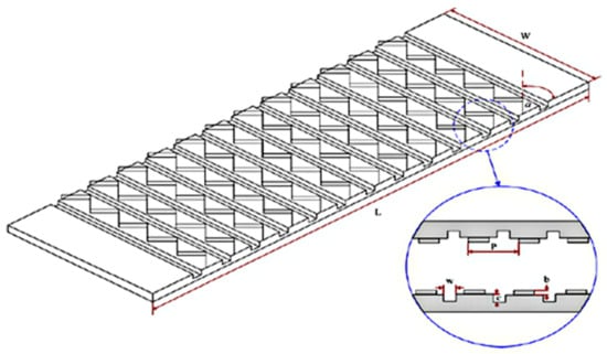
Figure 38.
Wavy-rib-grove turbulators [135].
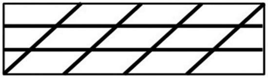
Figure 39.
45° angled and intersecting rib roughness [133].
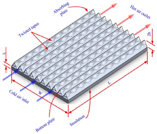
Figure 40.
V-shaped rib corrugated surface integrated with twisted tape [134].
5.22. Other Roughnesses
Singh and Singh [42] studied the effect of transverse ribs with a square wave type of profile (Figure 41) on the thermohydraulic performance of the SAH by using a CFD code. The value of Re varied from 3000 to 15,000, and p/e varied from 4 to 30. The value of e/Dh = 0.043 was fixed. The highest augmentations in friction factor and Nu were found to be 3.55 and 2.14 times that of the smooth duct at Re = 15,000. They reported the highest value of THPP as 1.43 at Re = 12,000 and p/e = 10. Ansari and Bazargan [136] investigated the effect of L/H, e/Dh, p/e, and W/H on the heat transfer performance of the SAH. They reported that the optimum value of e/Dh incremented as the value of the rate of flow decreased. The overall efficiency of the SAH was enhanced by more than 9% with the help of a ribbed surface. Alfarawi et al. [137] analyzed the effect of hybrid-rib roughness of rectangular and semicircular cross sections on the performance of the SAH. The study parameters encompassed p/e = 6.6 to 53.3 and Re = 12,500 to 86,500. The enhancements in the friction factor and Nu were 1.8 to 4.2 and 1.3 to 2.14, respectively. The highest increase in heat transfer was achieved at p/e = 6.6 in the case of hybrid ribs. Alam and Kim [138] numerically investigated the effect of a semi-elliptical-shaped obstacle type of roughness in a V-down pattern on the performance of the SAH. The parameter varied as α = 30°–90° and Re = 6000–18,000. The pattern of obstacles on the duct surface and α had a remarkable impact on thermal performance due to a high level of turbulence. The highest augmentations in f and Nu were 6.93 and 2.05, respectively, at α = 75° for a staggered pattern. Xiao et al. [139] numerically investigated the effect of inclined trapezoid-shape turbulators on the thermohydraulic performance of the SAH. Nu increased significantly, and energy efficiency was augmented by 24% and exergy efficiency was augmented by 31% over the smooth duct.
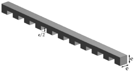
Figure 41.
Transverse rib with square wave type of profile [42].
Manjunath et al. [140] numerically investigated the effect of a sinusoidal profile type of a duct surface on the performance of the SAH. Re varied from 4000 to 24,000. The sinusoidal type of the surface enhanced the level of turbulence significantly, which led to a remarkable increment in convection coefficient. The thermal efficiency increased up to 12.5% over the smooth surface at the aspect ratio of the duct equaling 1.5. Bezbaruah et al. [141] studied the effect of a conical vortex generator type of artificial roughness on the performance of the SAH. They used experimental parameters as e/Dh = 0.17–0.34, Re = 3000–16,000, and p/e = 8–15. The highest value of Nu = 142.4 was achieved at e/Dh = 0.34, p/e = 8, and Re = 16,000 as that of a smooth duct. The highest value of f equaled 0.167 reported at p/e = 8, e/Dh = 0.34, and Re = 3500. The heat transfer performance was augmented by 192.2%. Dong et al. [142] numerically investigated the effect of an incline-grove ripple type of roughness on the performance of the SAH at Re in the range of 12,000–24,000. The incline-grove on the ripple surface enhanced the level of turbulence remarkably. The optimum value of α was near 45° to 60°.
Nu was augmented 1.04 to 1.946 times over the smooth surface. Alam et al. [143,144] numerically investigated the effects of conical protrusions on the thermohydraulic performance of the SAH. The study parameter varied as e/Dh = 0.02 to 0.044 and p/e = 6 to 12. The conical protrusion type of artificial rib roughness had a remarkable effect on the effective efficiency of the SAH. They reported the maximum value of effective efficiency as 70.92% at e/Dh = 0.0289 and p/e = 10. Kumar and Goel [145,146] analyzed the effects of a distinct type of rib roughness on the thermohydraulic performance of the SAH by using a triangular cross-section channel. The performance of the SAH strongly depended on the cross section of artificial roughness and also the cross section of a flow passage. A rectangular cross-section rib with forwarding chamfering showed the highest THPP at 2.75. Further, Goel et al. [147] analyzed the effect of the hemispherical dimple cavity type of roughness on the performance of the SAH by using a triangular cross-section channel. The leading edge of the dimple-cavity-type roughness showed lower heat transfer than that of a trailing edge. The highest augmentation value of Nu equal to 5.33 was achieved at Re = 2160. The value of THPP was equal to 3.48. Xi et al. [148] numerically studied a ribbed channel for Re ranging from 10,000 to 90,000. The study parameter ranged as e/D varying from 0.05 to 0.15 and rib angle varying from 30° to 90°.
6. Performance Evaluation Parameters
A large number of rib roughness geometries have been investigated by researchers, which are employed in the SAH [149,150,151]. The maximum augmentation in Nusselt number and friction factor is listed in Table 4 for ready reference. A Nusselt number and friction factor correlation were developed in terms of Reynolds number and roughness parameters for various rib configurations; the details are given in Table 5. The performance of a roughened duct depends on many parameters, such as e/Dh, α, p/e, Re, e/H, d/w, and W/H, and also on duct shape and size. These parameters are important for determining the Nu, friction factor, and THPP characteristic of the flow process in the duct of the SAH.
Table 4.
Early studies of friction factor and Nusselt number augmentation.
Table 5.
Correlations developed by researchers for different roughened surfaces.
7. Methodology and Formation of MATLAB Code for Calculating Thermal Efficiency
The flow chart of calculations as per the MATLAB program for calculating the thermal efficiency and heat loss coefficient of the duct with artificial roughnesses/turbulators is shown in Figure 42.
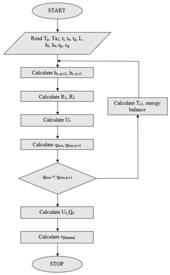
Figure 42.
Flow chart.
Solar energy I is absorbed by the collector plate, which is further transferred to the working fluid as heat loss from the bottom, useful heat gain, heat loss from the top cover, and heat loss from the side edges. The energy loses to the surroundings by convection and radiation from the top glass cover. The ambient and absorber plate temperatures are Ta and Tp, respectively. The step-by-step procedure for calculating the thermal efficiency is given below.
Heat exchange between the top glass cover and absorber plate:
where
Thermal resistance:
Convection coefficient of heat transfer between the top glass cover and the absorber plate:
where the Nusselt number between the glass cover and the absorber plate is given as [154]:
where the Rayleigh number:
The air physical properties are taken as α, β’, and υ at the mean temperature of the plate.
Radiation heat transfer coefficient:
Resistance to the surrounding:
Top loss coefficient:
Heat loss from the absorber to the ambient through the top glass cover:
The overall heat loss must be equal to the energy exchange between the plates:
The edge and back heat loss coefficient are calculated as:
Overall heat loss coefficient:
Useful heat gain to fluid [155]:
Thermal Efficiency of the collector:
8. Thermal Performance of Roughened SAH
The rough surface enhances the heat transfer rate over the smooth surface because of disrupting of the viscous sublayer, flow separation, secondary flow generation, and reattachment of flow, which leads to the enhancement of the level of turbulence adjacent to the heated surface. Due to an increase in the level of turbulence, the dead zone reduces remarkably where the convective rate of heat transfer is low. The turbulence promotors also increase friction losses, which leads to higher power consumption in the pumping of air because of high-pressure drops due to a high level of turbulence [156]. A high level of heat transfer and a small value of friction losses are the basic need of a compact and design-efficient SAH. In this regard, Nu/Nus and THPP help to select an optimum value of distinct roughness parameters and different rib arrangement patterns. Nu/Nus and THPP are determined with the help of corresponding correlations of f and Nu as listed in Table 5.
Nu/Nus and THPP increase significantly with the increase in Re for all shapes and sizes of roughness geometries. The Nu/Nus and THPP of different types of roughness with respect to Re are shown in Figure 43 and Figure 44, respectively. The values of Nu/Nus and THPP change from 0.75 to 14.20 and 0.39 to 5.58 in the Re range of 3000 to 24,000, respectively. The least values of Nu/Nus are recognized for the metal grit type of roughness and the highest value in the case of staggered broken-arc hybrid-rib roughness. The least values of THPP are recognized for the combination of inclined and transverse rib pattern and the highest value in case of S-type of the rib. The multiple V-rib with gaps, continuous multiribs, and multiarc ribs with a gap also show a higher value of THPP. However, the performance of S-type of the rib is not considerable at low RE, but at a higher Re performance it increases tremendously. The creation of gaps in the continuous ribs has shown remarkable improvement in the performance as compared with continuous ribs. The gap in ribs introduces a secondary flow in the stream of flow, which is generated due to vortices on the upstream side of the roughness. The secondary flow augments the level of turbulence remarkably due to its mixing with the main flow. The improvement in Nu due to the creation of gaps in the continuous ribs ranges from 1.1 to 1.3 times, and the corresponding increase in pumping power requirement ranges from 1.0 to 1.4 times.
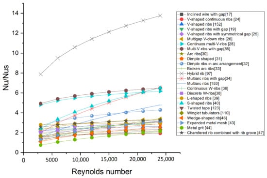
Figure 43.
Comparison of Nu/Nus of different types of roughened surfaces [17,19,24,25,26,28,30,31,32,33,34,36,38,39,40,43,44,46,47,85,97,110,123,152,153].
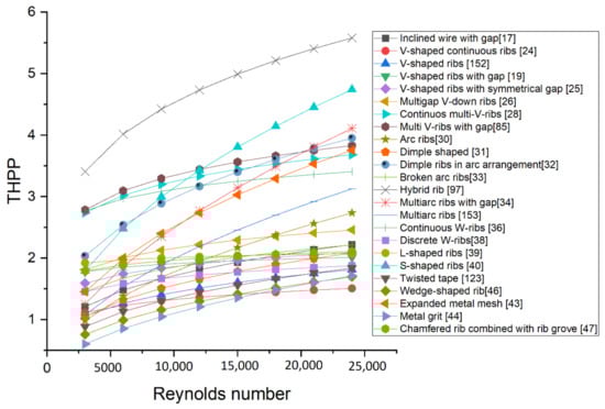
Figure 44.
Comparison of THPP of different types of roughened surfaces [17,19,24,25,26,28,30,31,32,33,34,36,38,39,40,43,44,46,47,85,97,110,123,152,153].
The thermal efficiency of the SAH increases significantly with the increase in Re for all shapes and sizes of artificial roughness geometry. The thermal efficiencies of a distinct type of roughness with respect to Re and ΔT/I are shown in Figure 45 and Figure 46, respectively. The value of thermal efficiency changes from 0.27 to 0.79. The least values of η are recognized for a twisted tape and delta-shaped vortex generator type of roughness and the highest value in the case of a staggered broken-arc hybrid rib. The multiple V-rib with gaps, continuous multiribs, and multiarc ribs with a gap also show higher values of η.
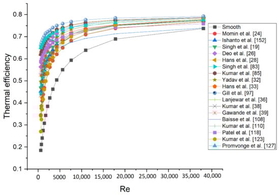
Figure 45.
Comparison of η of different types of roughened surface [19,24,26,28,32,33,36,38,39,83,85,97,108,110,118,123,127,152].
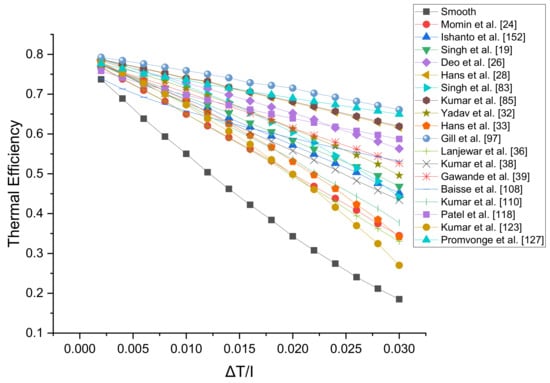
Figure 46.
Thermal efficiency vs. ΔT/I of different types of roughened surfaces [19,24,26,28,32,33,36,38,39,83,85,97,108,110,118,123,127,152].
9. Conclusions
An attempt has been made to study the thermal and friction characteristics of various artificial ribs/turbulators exploited in SAH ducts. The correlations of Nu and the friction factor for various rib configurations have been presented, and the thermohydraulic performance parameters of various rib configurations have been compared for a similar range of Reynolds number. Based on the literature review carried out in this paper, the following conclusions have been drawn.
- The shape and size of artificial roughness and their pattern of arrangements on the duct surface are the most important factors for the performance optimization of the SAH.
- The thermohydraulic characteristics of a large number of rib geometries have been investigated by many researchers. For most of the rib roughness geometries, the optimum performance has been achieved at the following parameters: p/e = 10, W/w = 6, α = 60°, and e/Dh = 0.043.
- THPP and thermal efficiency show the highest values in the case of staggered broken-arc type of hybrid rib and least values in the case of metal grit, twisted tape, and delta-shaped vortex generator type of roughness.
- The multi-V and multiarc-shaped roughnesses show higher thermohydraulic performance over other roughness geometries. The introducing gaps in the limb of multi-V-ribs enhance the level of turbulence significantly.
- The multi-V-shaped ribs show a higher value of the friction factor, and arc-shaped circular dimples show a lower value of the friction factor.
- The broken-arc-shaped rib combined with a staggered-arc rib piece has better performance than broken-arc-shaped and arc-shaped rib roughness.
- The creation of gaps in the continuous ribs has shown remarkable improvement in thermohydraulic performance over the continuous ribs. The improvement in Nu due to the creation of gaps in the continuous ribs ranges from 1.1 to 1.3 times, and corresponding increase in pumping power requirement ranges from 1.0 to 1.4 times.
- THPP shows higher values in the case of an S-shape rib, multi-V ribs, and arc-shaped roughnesses with gaps. However, the performance of an S-shaped rib is not considerable at low Re, but the performance increases remarkably with the increase in Re.
- The arc arrangement of rib roughness shows lower value pressure losses over the V-shaped arrangement due to the curved nature of the induced secondary flow along with the roughness.
- In general, higher roughnesses’ height has a higher Nusselt number; however, higher roughnesses’ height contributes to higher pressure drop. Therefore, the thermohydraulic performance of roughnesses needs to be optimized. In this regard, net effective efficiency is the best tool to analyze roughnesses. On the basis of net effective efficiency, a multiarc rib with gaps is found to be best around 79% in comparison with other rib configurations, which is recommended for overall better performance.
The work presented in this review paper was carried out as a convective heat transfer coefficient from the absorber plate. Apart from performance improvement by heat transfer enhancement, there is a tremendous scope to further increase the performance of the SAH by exploiting more advanced active methods, such as electrodynamics, jet spray, mechanical aid, surface vibration, and fluid vibration. Further, heat loss through a top glass cover needs to be minimized by optimizing the natural convection between the glass cover and the absorber or utilizing the vacuum between them. Additionally, the flow structure should be studied using flow visualization, such as PIV, LCT, and CFD, to achieve the optimum rib arrangement.
Author Contributions
Conceptualization, K., T.A. and N.K.G.; methodology, K. and T.A.; software, K. and T.A.; validation, K. and T.A.; formal analysis, N.K.G. and R.C.; investigation, K. and T.A.; resources, R.C. and G.B.; data curation, K.; writing—original draft preparation, K. and T.A.; writing—review and editing K., T.A., N.K.G., R.C. and G.B.; visualization, K., T.A. and N.K.G.; supervision, T.A., R.C. and G.B.; project administration, T.A., R.C. and G.B. All authors have read and agreed to the published version of the manuscript.
Funding
This research received no external funding.
Institutional Review Board Statement
Not applicable.
Informed Consent Statement
Not applicable.
Data Availability Statement
The data are not publicly available due to privacy considerations.
Conflicts of Interest
The authors declare no conflict of interest.
Nomenclature
| Symbol | Title | Unit |
| b | Roughness width | m |
| c | Characteristic separation length | m |
| d’ | Diameter of dimples | m |
| d/x | Relative gap position | - |
| dR | Relative punched hole size | - |
| D | Pipe inside diameter (to base of ribs) | m |
| De | Equivalent diameter of annulus (d1 − d2) | m |
| Dh | Hydraulic diameter of duct | m |
| e | Height of roughness element | m |
| e+ | Roughness Reynolds number | - |
| e/Dh | Relative roughness height | - |
| e/H | Blockage ratio | - |
| fs | Smooth surface friction factor | - |
| f | Friction factor of roughened surface | - |
| FR | Heat removal factor | - |
| g | Roughness function of heat transfer | - |
| g/e | Relative gap width | - |
| H | Duct height | m |
| I | Insolation | W/m2 |
| L | Length of test section | m |
| Nu | Nusselt number | - |
| Ng | Number of gaps on half arc | - |
| p/g | Relative pitch-to-gap ratio | - |
| p’/p | Relative staggered rib pitch | - |
| p/H | Rib-pitch-to-channel-height ratio | - |
| Pt/b | Relative longitudinal length of obstacles | - |
| Pt/e | Relative transversal length of obstacles | - |
| PR | Relative winglet pitch | - |
| Qu | Heat gain | W |
| Qe+ | Heat transfer function | - |
| r/e | Relative staggered rib size | - |
| R | Momentum transfer roughness function | - |
| Ra | Rayleigh number | - |
| Re | Reynolds number | - |
| S | Short way length between dimples | m |
| s’/s | Relative gap position | - |
| St | Stanton number | - |
| Ta | Ambient temperature | K |
| Ti | Air inlet temperature | K |
| Tf | Mean air temperature | K |
| Tp | Plate temperature | K |
| Tw | Wall temperature | K |
| ΔP | Pressure drops | N/m2 |
| UO | Overall heat loss coefficient | W/m2·K |
| V | Velocity of air in the SAH duct | m/s |
| w/e | Staggered rib length to rib height | - |
| W/e | Width-to-height ratio | - |
| W/H | Width-to-duct-height ratio | - |
| W/w | Relative roughness width | - |
| W1/w | Relative gap position | - |
| x | Distance from starting | m |
| η | Thermohydraulic performance parameter | - |
| ηth | Thermal efficiency of solar collectors | - |
| Ρ | Density | kg/m3 |
| Temperature factor Tw/Tf | - | |
| α | Angle of attack | degree |
| α’ | Arc angle | degree |
| α/90 | Relative arc angle | - |
| Chamfering angle of rib | degree | |
| β | Slope | degree |
| β’ | Thermal expansion coefficient of air | 1/K |
| εg | Glass cover emissivity | |
| εp | Absorber plate emissivity | |
| υ | Kinematic viscosity | m2/s |
| τ | Transmissivity | |
| σ | Stefan–Boltzmann constant | W/m2·K4 |
References
- Gupta, N.K.; Karmveer; Alam, T. A Review on Augmentation in Thermal Performance of Solar Air Heater. IOP Conf. Series Mater. Sci. Eng. 2021, 1116, 012064. [Google Scholar] [CrossRef]
- Bliss, R.W. The derivations of several “Plate-efficiency factors” useful in the design of flat-plate solar heat collectors. Sol. Energy 1959, 3, 55–64. [Google Scholar] [CrossRef]
- Lewis, M.J. Optimizing the thermo-hydraulic performance of rough surfaces. Int. J. Heat Mass Transf. 1975, 18, 1243–1248. [Google Scholar] [CrossRef]
- Okamoto, S.; Seo, S.; Nakaso, K.; Kawai, I. Turbulent shear flow and heat transfer over the repeated two-dimensional square ribs on ground plane. J. Fluids Eng. Trans ASME 1993, 115, 631–637. [Google Scholar] [CrossRef]
- Sparrow, E.M.; Kang, S.S.; Chuck, W. Relation between the points of flow reattachment and maximum heat transfer for regions of flow separation. Int. J. Heat Mass Transf. 1987, 30, 1237–1246. [Google Scholar] [CrossRef]
- Cortés, A.; Piacentini, R. Improvement of the efficiency of a bare solar collector by means of turbulence promoters. Appl. Energy 1990, 36, 253–261. [Google Scholar] [CrossRef]
- Nikuradse, J. Laws of Flow in Rough Pipes. J. Appl. Phys. 1950, 3, 399. [Google Scholar]
- Dipprey, D.F.; Sabersky, R.H. Heat and momentum transfer in smooth and rough tubes at various prandtl numbers. Int. J. Heat Mass Transf. 1963, 6, 329–353. [Google Scholar] [CrossRef]
- Webb, R.L.; Eckert, E.R.G.; Goldstein, R.J. Heat transfer and friction in tubes with repeated-rib roughness. Int. J. Heat Mass Transf. 1971, 14, 601–617. [Google Scholar] [CrossRef]
- Webb, R.L.; Eckert, E.R.G.; Goldstein, R.J. Generalized heat transfer and friction correlations for tubes with repeated-rib roughness. Int. J. Heat Mass Transf. 1972, 15, 180–184. [Google Scholar] [CrossRef]
- Vilemas, J.V.; Šimonis, V.M. Heat transfer and friction of rough ducts carrying gas flow with variable physical properties. Int. J. Heat Mass Transf. 1985, 28, 59–68. [Google Scholar] [CrossRef]
- Han, J.C.; Glicksman, L.R.; Rohsenow, W.M. An investigation of heat transfer and friction for rib-roughened surfaces. Int. J. Heat Mass Transf. 1978, 21, 1143–1156. [Google Scholar] [CrossRef]
- Prasad, B.N.; Saini, J.S. Effect of artificial roughness on heat transfer and friction factor in a solar air heater. Sol. Energy 1988, 41, 555–560. [Google Scholar] [CrossRef]
- Gupta, D.; Solanki, C.; Saini, J.S. Heat and fluid flow in rectangular solar air heater ducts having transverse rib roughness on absorber plates. Sol. Energy 1993, 51, 31–37. [Google Scholar] [CrossRef]
- Boulemtafes-Boukadoum, A.; Absi, R.; El Abbassi, I.; Darcherif, M.; Benzaoui, A. Numerical investigation of absorber’s roughness effect on heat transfer in upward solar air heaters. Energy Procedia 2019, 157, 1089–1100. [Google Scholar] [CrossRef]
- Singh, S.; Singh, B.; Hans, V.S.; Gill, R.S. CFD (computational fluid dynamics) investigation on Nusselt number and friction factor of solar air heater duct roughened with non-uniform cross-section transverse rib. Energy 2015, 84, 509–517. [Google Scholar] [CrossRef]
- Aharwal, K.R.; Gandhi, B.K.; Saini, J.S. Heat transfer and friction characteristics of solar air heater ducts having integral inclined discrete ribs on absorber plate. Int. J. Heat Mass Transf. 2009, 52, 5970–5977. [Google Scholar] [CrossRef]
- Singh, S.; Chander, S.; Saini, J.S. Investigations on thermo-hydraulic performance due to flow-attack-angle in V-down rib with gap in a rectangular duct of solar air heater. Appl. Energy 2012, 97, 907–912. [Google Scholar] [CrossRef]
- Singh, S.; Chander, S.; Saini, J.S. Heat transfer and friction factor correlations of solar air heater ducts artificially roughened with discrete V-down ribs. Energy 2011, 36, 5053–5064. [Google Scholar] [CrossRef]
- Sahu, M.M.; Bhagoria, J.L. Augmentation of heat transfer coefficient by using 90° broken transverse ribs on absorber plate of solar air heater. Renew. Energy 2005, 30, 2057–2073. [Google Scholar] [CrossRef]
- Yadav, A.S.; Bhagoria, J.L. A CFD based thermo-hydraulic performance analysis of an artificially roughened solar air heater having equilateral triangular sectioned rib roughness on the absorber plate. Int. J. Heat Mass Transf. 2014, 70, 1016–1039. [Google Scholar] [CrossRef]
- Yadav, A.S.; Bhagoria, J.L. A numerical investigation of square sectioned transverse rib roughened solar air heater. Int. J. Therm. Sci. 2014, 79, 111–131. [Google Scholar] [CrossRef]
- Gupta, D.; Solanki, S.C.; Saini, J.S. Thermohydraulic performance of solar air heaters with roughened absorber plates. Sol. Energy 1997, 61, 33–42. [Google Scholar] [CrossRef]
- Ebrahim-Momin, A.M.; Saini, J.S.; Solanki, S.C. Heat transfer and friction in solar air heater duct with V-shaped rib roughness on absorber plate. Int. J. Heat Mass Transf. 2002, 45, 3383–3396. [Google Scholar] [CrossRef]
- Maithani, R.; Saini, J.S. Heat transfer and friction factor correlations for a solar air heater duct roughened artificially with V-ribs with symmetrical gaps. Exp. Therm. Fluid Sci. 2016, 70, 220–227. [Google Scholar] [CrossRef]
- Deo, N.S.; Chander, S.; Saini, J.S. Performance analysis of solar air heater duct roughened with multigap V-down ribs combined with staggered ribs. Renew. Energy 2016, 91, 484–500. [Google Scholar] [CrossRef]
- Patil, A.K.; Saini, J.S.; Kumar, K. Heat transfer and friction characteristics of solar air heater duct roughened by broken V-shape ribs combined with staggered rib piece. J. Renew. Sustain. Energy 2012, 4, 013115. [Google Scholar] [CrossRef]
- Hans, V.S.; Saini, R.P.; Saini, J.S. Heat transfer and friction factor correlations for a solar air heater duct roughened artificially with multiple v-ribs. Sol. Energy 2010, 84, 898–911. [Google Scholar] [CrossRef]
- Kumar, A.; Saini, R.P.; Saini, J.S. Experimental investigation on heat transfer and fluid flow characteristics of air flow in a rectangular duct with Multi V-shaped rib with gap roughness on the heated plate. Sol. Energy 2012, 86, 1733–1749. [Google Scholar] [CrossRef]
- Saini, S.K.; Saini, R.P. Development of correlations for Nusselt number and friction factor for solar air heater with roughened duct having arc-shaped wire as artificial roughness. Sol. Energy 2008, 82, 1118–1130. [Google Scholar] [CrossRef]
- Sethi, M.; Thakur, N.S. Correlations for solar air heater duct with dimpled shape roughness elements on absorber plate. Sol. Energy 2012, 86, 2852–2861. [Google Scholar] [CrossRef]
- Yadav, S.; Kaushal, M.; Varun; Siddhartha. Nusselt number and friction factor correlations for solar air heater duct having protrusions as roughness elements on absorber plate. Exp. Therm. Fluid Sci. 2013, 44, 34–41. [Google Scholar] [CrossRef]
- Hans, V.S.; Gill, R.S.; Singh, S. Heat transfer and friction factor correlations for a solar air heater duct roughened artificially with broken arc ribs. Exp. Therm. Fluid Sci. 2016, 80, 77–89. [Google Scholar] [CrossRef]
- Pandey, N.K.; Bajpai, V.K. Experimental investigation of heat transfer augmentation using multiple arcs with gap on absorber plate of solar air heater. Sol. Energy 2016, 134, 314–326. [Google Scholar] [CrossRef]
- Singh, A.P.; Varun; Siddhartha. Effect of artificial roughness on heat transfer and friction characteristics having multiple arc shaped roughness element on the absorber plate. Sol. Energy 2014, 105, 479–493. [Google Scholar] [CrossRef]
- Lanjewar, A.M.; Bhagoria, J.L.; Sarviya, R.M.; Lanjewar, A.M.; Bhagoria, L. Performance analysis of W-shaped rib roughened solar air heater. J. Renew. Sustain. Energy 2011, 3, 043110. [Google Scholar] [CrossRef]
- Lanjewar, A.; Bhagoria, J.L.; Sarviya, R.M. Experimental study of augmented heat transfer and friction in solar air heater with different orientations of W-Rib roughness. Exp. Therm. Fluid Sci. 2011, 35, 986–995. [Google Scholar] [CrossRef]
- Kumar, A.; Bhagoria, J.L.; Sarviya, R.M. Heat transfer and friction correlations for artificially roughened solar air heater duct with discrete W-shaped ribs. Energy Convers. Manag. 2009, 50, 2106–2117. [Google Scholar] [CrossRef]
- Gawande, V.B.; Dhoble, A.S.; Zodpe, D.B.; Chamoli, S. Experimental and CFD investigation of convection heat transfer in solar air heater with reverse L-shaped ribs. Sol. Energy 2016, 131, 275–295. [Google Scholar] [CrossRef]
- Kumar, K.; Prajapati, D.R.; Samir, S. Heat Transfer and Friction Factor Correlations Development for Solar Air artificially roughened with ‘S’shape ribs. Heater Duct. Exp. Therm. Fluid Sci. 2016, 82, 249–261. [Google Scholar] [CrossRef]
- Bhushan, B.; Singh, R. Nusselt number and friction factor correlations for solar air heater duct having artificially roughened absorber plate. Sol. Energy 2011, 85, 1109–1118. [Google Scholar] [CrossRef]
- Singh, I.; Singh, S. CFD analysis of solar air heater duct having square wave profiled transverse ribs as roughness elements. Sol. Energy 2018, 162, 442–453. [Google Scholar] [CrossRef]
- Saini, R.P.; Saini, J.S. Heat transfer and friction factor correlations for artificially roughened ducts with expanded metal mesh as roughness element. Int. J. Heat Mass Transf. 1997, 40, 973–986. [Google Scholar] [CrossRef]
- Karmare, S.V.; Tikekar, A.N. Heat transfer and friction factor correlation for artificially roughened duct with metal grit ribs. Int. J. Heat Mass Transf. 2007, 50, 4342–4351. [Google Scholar] [CrossRef]
- Karwa, R. Experimental studies of augmented heat transfer and friction in asymmetrically heated rectangular ducts with ribs on the heated wall in transverse, inclined, v-continuous and v-discrete pattern. Int. Commun. Heat Mass Transf. 2003, 30, 241–250. [Google Scholar] [CrossRef]
- Saini, R.P.; Verma, J. Heat transfer and friction factor correlations for a duct having dimple-shape artificial roughness for solar air heaters. Energy 2008, 33, 1277–1287. [Google Scholar] [CrossRef]
- Bhagoria, J.L.; Saini, J.S.; Solanki, S.C. Heat transfer coefficient and friction factor correlations for rectangular solar air heater duct having transverse wedge shaped rib roughness on the absorber plate. Renew. Energy 2002, 25, 341–369. [Google Scholar] [CrossRef]
- Layek, A.; Saini, J.S.; Solanki, S.C. Heat transfer and friction characteristics for artificially roughened ducts with compound turbulators. Int. J. Heat Mass Transf. 2007, 50, 4845–4854. [Google Scholar] [CrossRef]
- Ahn, S.W. The effects of roughness types on friction factors and heat transfer in roughened rectangular duct. Int. Commun. Heat Mass Transf. 2001, 28, 933–942. [Google Scholar] [CrossRef]
- Taslim, M.E.; Li, T.; Kercher, D.M. Experimental heat transfer and friction in channels roughened with angled, V-shaped and discrete ribs on two opposite walls. ASME J. Turbomach. 1996, 118, 20–28. [Google Scholar] [CrossRef]
- Alam, T.; Saini, R.P.; Saini, J.S. Use of turbulators for heat transfer augmentation in an air duct-A review. Renew. Energy 2014, 62, 689–715. [Google Scholar] [CrossRef]
- Sahu, R.K.; Gandhi, B.K. Numerical Simulation of Heat Transfer Enhancement due to a Gap in an Inclined Continuous Rib Arrangement in a Solar Air Heater Duct. Int. J. Adv. Mech. Eng. 2014, 4, 687–693. [Google Scholar]
- Aharwal, K.R.; Gandhi, B.K.; Saini, J.S. An experimental investigation of heat transfer and fluid flow in a rectangular duct with inclined discrete ribs. Int. J. Energy Environ. 2010, 1, 987–998. [Google Scholar]
- Xi, L.; Xu, L.; Gao, J.; Zhao, Z.; Li, Y. Study on heat transfer performance of steam-cooled ribbed channel using neural networks and genetic algorithms. Int. J. Heat Mass Transf. 2018, 127, 1110–1123. [Google Scholar] [CrossRef]
- Sherry, M.; Lo Jacono, D.; Sheridan, J. An experimental investigation of the recirculation zone formed downstream of a forward-facing step. J. Wind Eng. Ind. Aerodyn. 2010, 98, 888–894. [Google Scholar] [CrossRef] [Green Version]
- Essel, E.E.; Nematollahi, A.; Thacher, E.W.; Tachie, M.F. Effects of upstream roughness and Reynolds number on separated and reattached turbulent flow. J. Turbul. 2015, 16, 872–899. [Google Scholar] [CrossRef]
- Singh, I.; Vardhan, S.; Singh, S.; Singh, A. Experimental and CFD analysis of solar air heater duct roughened with multiple broken transverse ribs: A comparative study. Sol. Energy 2019, 188, 519–532. [Google Scholar] [CrossRef]
- Prasad, K.; Mullick, S.C. Heat transfer characteristics of a solar air heater used for drying purposes. Appl. Energy 1983, 13, 83–93. [Google Scholar] [CrossRef]
- Karwa, R.; Solanki, S.C.; Saini, J.S. Thermo-hydraulic performance of solar air heaters having integral chamfered rib roughness on absorber plates. Energy 2001, 26, 161–176. [Google Scholar] [CrossRef]
- Verma, S.K.; Prasad, B.N. Investigation for the optimal thermo-hydraulic performance of artificially roughened solar air heaters. Renew. Energy 2000, 20, 19–36. [Google Scholar] [CrossRef]
- Xi, L.; Xu, L.; Gao, J.; Zhao, Z.; Li, Y. Numerical analysis and optimization on flow and heat transfer performance of a steam-cooled ribbed channel. Case Stud. Therm. Eng. 2021, 28, 101442. [Google Scholar] [CrossRef]
- Behura, A.K.; Rout, S.K.; Pandya, H.; Kumar, A. Thermal Analysis of Three Sides Artificially Roughened Solar Air Heaters. Energy Procedia 2017, 109, 279–285. [Google Scholar] [CrossRef]
- Aharwal, K.R.; Gandhi, B.K.; Saini, J.S. Experimental investigation on heat-transfer enhancement due to a gap in an inclined continuous rib arrangement in a rectangular duct of solar air heater. Renew. Energy 2008, 33, 585–596. [Google Scholar] [CrossRef]
- Lu, B.; Jiang, P.X. Experimental and numerical investigation of convection heat transfer in a rectangular channel with angled ribs. Exp. Therm. Fluid Sci. 2006, 30, 513–521. [Google Scholar] [CrossRef]
- Alam, T.; Kim, M.-H. A critical review on artificial roughness provided in rectangular solar air heater duct. Renew. Sustain. Energy Rev. 2017, 69, 387–400. [Google Scholar] [CrossRef]
- Patil, A.K. Heat transfer mechanism and energy efficiency of artificially roughened solar air heaters—A review. Renew. Sustain. Energy Rev. 2015, 42, 681–689. [Google Scholar] [CrossRef]
- Singh, S.; Chander, S.; Saini, J.S. Thermal and effective efficiency-based analysis of discrete V-down rib-roughened solar air heaters. J. Renew. Sustain. Energy 2011, 3, 023107. [Google Scholar] [CrossRef]
- Singh, S.; Chander, S.; Saini, J.S. Thermo-hydraulic performance due to relative roughness pitch in V-down rib with gap in solar air heater duct—Comparison with similar rib roughness geometries. Renew. Sustain. Energy Rev. 2015, 43, 1159–1166. [Google Scholar] [CrossRef]
- Karwa, R.; Bairwa, R.D.; Jain, B.P.; Karwa, N. Experimental study of the effects of rib angle and discretization on heat transfer and friction in an asymmetrically heated rectangular duct. J. Enhanc. Heat Transf. 2005, 12, 343–355. [Google Scholar] [CrossRef]
- Jain, P.K.; Lanjewar, A. Overview of V-RIB geometries in solar air heater and performance evaluation of a new V-RIB geometry. Renew. Energy 2019, 133, 77–90. [Google Scholar] [CrossRef]
- Kumar, A.; Kim, M.H. Heat transfer and fluid flow characteristics in air duct with various V-pattern rib roughness on the heated plate: A comparative study. Energy 2016, 103, 75–85. [Google Scholar] [CrossRef]
- Kumar, A.; Kim, M.H. Thermo-hydraulic performance of rectangular ducts with different multiple V-rib roughness shapes: A comprehensive review and comparative study. Renew. Sustain. Energy Rev. 2016, 54, 635–652. [Google Scholar] [CrossRef]
- Nidhul, K.; Kumar, S.; Yadav, A.K.; Anish, S. Enhanced thermo-hydraulic performance in a V-ribbed triangular duct solar air heater: CFD and exergy analysis. Energy 2020, 200, 117448. [Google Scholar] [CrossRef]
- Misra, R.; Singh, J.; Jain, S.K.; Faujdar, S.; Agrawal, M.; Mishra, A. Prediction of behavior of triangular solar air heater duct using V-down rib with multiple gaps and turbulence promoters as artificial roughness: A CFD analysis. Int. J. Heat Mass Transf. 2020, 162, 120376. [Google Scholar] [CrossRef]
- Patel, S.S.; Lanjewar, A. Experimental and numerical investigation of solar air heater with novel V-rib geometry. J. Energy Storage 2019, 21, 750–764. [Google Scholar] [CrossRef]
- Patel, S.S.; Lanjewar, A. Heat transfer enhancement using additional gap in symmetrical element of V-geometry roughened solar air heater. J. Energy Storage 2021, 38, 102545. [Google Scholar] [CrossRef]
- Alam, T.; Saini, R.P.; Saini, J.S. Experimental investigation on heat transfer enhancement due to V-shaped perforated blocks in a rectangular duct of solar air heater. Energy Convers. Manag. 2014, 81, 374–383. [Google Scholar] [CrossRef]
- Alam, T.; Saini, R.P.; Saini, J.S. Experimental investigation of thermo hydraulic performance due to angle of attack in solar air heater duct equipped with V-shaped perforated blockages. Int. J. Renew. Energy Technol. 2015, 6, 164–180. [Google Scholar] [CrossRef]
- Alam, T.; Saini, R.P.; Saini, J.S. Experimental investigation of thermo-hydraulic performance of a rectangular solar air heater duct equipped with V-shaped perforated blocks. Adv. Mech. Eng. 2014, 6, 948313. [Google Scholar] [CrossRef]
- Alam, T.; Saini, R.P.; Saini, J.S. Heat transfer enhancement due to V-shaped perforated blocks in a solar air heater duct. Appl. Mech. Mater. 2014, 619, 125–129. [Google Scholar] [CrossRef]
- Alam, T.; Saini, R.P.; Saini, J.S. Effect of circularity of perforation holes in V-shaped blockages on heat transfer and friction characteristics of rectangular solar air heater duct. Energy Convers. Manag. 2014, 86, 952–963. [Google Scholar] [CrossRef]
- Singh Bisht, V.; Kumar Patil, A.; Gupta, A. Review and performance evaluation of roughened solar air heaters. Renew. Sustain. Energy Rev. 2018, 81, 954–977. [Google Scholar] [CrossRef]
- Singh, A.; Kumar, R.; Singh, P.; Goel, V. Solar air heater having multiple V-ribs with Multiple-Symmetric gaps as roughness elements on Absorber-Plate: A parametric study. Sustain. Energy Technol. Assess. 2021, 48, 101559. [Google Scholar] [CrossRef]
- Kumar, A.; Saini, R.P.; Saini, J.S. Experimental Investigations on Thermo-hydraulic Performance due to Flow- Attack- Angle in Multiple V-ribs with Gap in a Rectangular Duct of Solar Air Heaters. J. Sustain. Energy Environ. 2013, 4, 1–7. [Google Scholar]
- Kumar, A.; Saini, R.P.; Saini, J.S. Development of correlations for Nusselt number and friction factor for solar air heater with roughened duct having multi-V-shaped with gap rib as arti fi cial roughness. Renew. Energy 2013, 58, 151–163. [Google Scholar] [CrossRef]
- Jin, D.; Zhang, M.; Wang, P.; Xu, S. Numerical investigation of heat transfer and fluid flow in a solar air heater duct with multi-V-shaped ribs on the absorber plate. Energy 2015, 89, 178–190. [Google Scholar] [CrossRef]
- Jin, D.; Zuo, J.; Quan, S.; Xu, S.; Gao, H. Thermo-hydraulic performance of solar air heater with staggered multiple V-shaped ribs on the absorber plate. Energy 2017, 127, 68–77. [Google Scholar] [CrossRef]
- Jin, D.; Quan, S.; Zuo, J.; Xu, S. Numerical investigation of heat transfer enhancement in a solar air heater roughened by multiple V-shaped ribs. Renew. Energy 2018, 134, 78–88. [Google Scholar] [CrossRef]
- Promvonge, P.; Skullong, S. Thermal characteristics in solar air duct with V-shaped flapped-baffles and chamfered-grooves. Int. J. Heat Mass Transf. 2021, 172, 121220. [Google Scholar] [CrossRef]
- Sahu, M.K.; Prasad, R.K. Exergy based performance evaluation of solar air heater with arc- shaped wire roughened absorber plate. Renew. Energy 2016, 96, 233–243. [Google Scholar] [CrossRef]
- Gill, R.S.; Hans, V.S.; Saini, J.S.; Singh, S. Investigation on performance enhancement due to staggered piece in a broken arc rib roughened solar air heater duct. Renew. Energy 2016, 104, 148–162. [Google Scholar] [CrossRef]
- Gill, R.S.; Hans, V.S.; Singh, S. Investigations on thermo-hydraulic performance of broken arc rib in a rectangular duct of solar air heater. Int. Commun. Heat Mass Transf. 2017, 88, 20–27. [Google Scholar] [CrossRef]
- Ghritlahre, H.K.; Sahu, P.K.; Chand, S. Thermal performance and heat transfer analysis of arc shaped roughened solar air heater—An experimental study. Sol. Energy 2020, 199, 173–182. [Google Scholar] [CrossRef]
- Yadav, K.D.; Prasad, R.K. Performance analysis of parallel flow flat plate solar air heater having arc shaped wire roughened absorber plate. Renew. Energy Focus 2020, 32, 23–44. [Google Scholar] [CrossRef]
- Ambade, J.; Lanjewar, A. Experimental investigation of solar air heater with new symmetrical GAP ARC GEOMETRY and staggered element. Int. J. Therm. Sci. 2019, 146, 106093. [Google Scholar] [CrossRef]
- Azad, R.; Bhuvad, S.; Lanjewar, A. Study of solar air heater with discrete arc ribs geometry: Experimental and numerical approach. Int. J. Therm. Sci. 2021, 167, 107013. [Google Scholar] [CrossRef]
- Gill, R.S.; Hans, V.S.; Singh, R.P. Optimization of artificial roughness parameters in a solar air heater duct roughened with hybrid ribs. Appl. Therm. Eng. 2021, 191, 116871. [Google Scholar] [CrossRef]
- Sureandhar, G.; Srinivasan, G.; Muthukumar, P.; Senthilmurugan, S. Performance analysis of arc rib fin embedded in a solar air heater. Therm. Sci. Eng. Prog. 2021, 23, 100891. [Google Scholar] [CrossRef]
- Kumar, R.; Goel, V.; Singh, P.; Saxena, A.; Singh, A. Performance evaluation and optimization of solar assisted air heater with discrete multiple arc shaped ribs. J. Energy Storage 2019, 26, 100978. [Google Scholar] [CrossRef]
- Saravanakumar, P.T.; Somasundaram, D.; Matheswaran, M.M. Thermal and thermo-hydraulic analysis of arc shaped rib roughened solar air heater integrated with fins and baffles. Sol. Energy 2019, 180, 360–371. [Google Scholar] [CrossRef]
- Saravanakumar, P.T.; Somasundaram, D.; Matheswaran, M.M. Exergetic investigation and optimization of arc shaped rib roughened solar air heater integrated with fins and baffles. Appl. Therm. Eng. 2020, 175, 115316. [Google Scholar] [CrossRef]
- Agrawal, Y.; Bhagoria, J.L. Proceedings Experimental investigation for pitch and angle of arc effect of discrete artificial roughness on Nusselt number and fluid flow characteristics of a solar air heater. Mater. Today Proc. 2020, 46, 5506–5511. [Google Scholar] [CrossRef]
- Hassan, A.K.; Hasan, M.M.; Khan, M.E. Parametric investigation and correlation development for heat transfer and friction factor in multiple arc dimple roughened solar air duct. Renew. Energy 2021, 174, 403–425. [Google Scholar] [CrossRef]
- Agrawal, Y.; Bhagoria, J.L.; Pagey, V.S. Materials Today: Proceedings Enhancement of thermo-hydraulic performance using double arc reverse ribs in a solar collector: Experimental approach. Mater. Today Proc. 2021, 47, 5749–6336. [Google Scholar] [CrossRef]
- Kumar, A.; Behura, A.K.; Saboor, S.; Gupta, H.K. Comparative study on W-shaped roughened solar air heaters by using booster mirror. Mater. Today Proc. 2020, 46, 5675–5680. [Google Scholar] [CrossRef]
- Singh, I.; Singh, S. A review of artificial roughness geometries employed in solar air heaters. Renew. Sustain. Energy Rev. 2018, 92, 405–425. [Google Scholar] [CrossRef]
- Wang, D.; Liu, J.; Liu, Y.; Wang, Y.; Li, B.; Liu, J. Evaluation of the performance of an improved solar air heater with “S” shaped ribs with gap. Sol. Energy 2020, 195, 89–101. [Google Scholar] [CrossRef]
- Baissi, M.T.; Brima, A.; Aoues, K.; Khanniche, R.; Moummi, N. Thermal behavior in a solar air heater channel roughened with delta-shaped vortex generators. Appl. Therm. Eng. 2019, 165, 113563. [Google Scholar] [CrossRef]
- Kumar, A.; Layek, A. Nusselt number and friction characteristics of a solar air heater that has a winglet type vortex generator in the absorber surface. Exp. Therm. Fluid Sci. 2020, 119, 110204. [Google Scholar] [CrossRef]
- Kumar, A.; Layek, A. Nusselt number and friction factor correlation of solar air heater having winglet type vortex generator over absorber plate. Sol. Energy 2020, 205, 334–348. [Google Scholar] [CrossRef]
- Kumar, R.; Kumar, S.; Thapa, S.; Sethi, M.; Fekete, G.; Singh, T. Impact of artificial roughness variation on heat transfer and friction characteristics of solar air heating system. Alex. Eng. J. 2021, 61, 481–491. [Google Scholar] [CrossRef]
- Promvonge, P.; Promthaisong, P.; Skullong, S. Numerical heat transfer in a solar air heater duct with punched delta-winglet vortex generators. Case Stud. Therm. Eng. 2021, 26, 101088. [Google Scholar] [CrossRef]
- Mahanand, Y.; Senapati, J.R. Thermo-hydraulic performance analysis of a solar air heater (SAH) with quarter-circular ribs on the absorber plate: A comparative study. Int. J. Therm. Sci. 2021, 161, 106747. [Google Scholar] [CrossRef]
- Gilani, S.E.; Al-kayiem, H.H.; Woldemicheal, D.E.; Gilani, S.I. Performance enhancement of free convective solar air heater by pin protrusions on the absorber. Sol. Energy 2017, 151, 173–185. [Google Scholar] [CrossRef]
- Perwez, A.; Kumar, R. Thermal performance investigation of the fl at and spherical dimple absorber plate solar air heaters. Sol. Energy 2019, 193, 309–323. [Google Scholar] [CrossRef]
- Debnat, S.; Das, B.; Randive, P. Influences of pentagonal ribs on the performance of rectangular solar air heater. Energy Procedia 2019, 158, 1168–1173. [Google Scholar] [CrossRef]
- Antony, A.L.; Shetty, S.P.; Madhwesh, N.; Sharma, N.Y.; Karanth, K.V. Influence of stepped cylindrical turbulence generators on the thermal enhancement factor of a flat plate solar air heater. Sol. Energy 2020, 198, 295–310. [Google Scholar] [CrossRef]
- Patel, Y.M.; Jain, S.V.; Lakhera, V.J. Thermo-hydraulic performance analysis of a solar air heater roughened with reverse NACA profile ribs. Appl. Therm. Eng. 2020, 170, 114940. [Google Scholar] [CrossRef]
- Gabhane, M.G.; Kanase-Patil, A.B. Experimental analysis of double flow solar air heater with multiple C shape roughness. Sol. Energy 2017, 155, 1411–1416. [Google Scholar] [CrossRef]
- Saravanan, A.; Murugan, M.; Reddy, M.S.; Ranjit, P.S.; Elumalai, P.V.; Kumar, P.; Sree, S.R. Thermo-hydraulic performance of a solar air heater with staggered C-shape finned absorber plate. Int. J. Therm. Sci. 2021, 168, 107068. [Google Scholar] [CrossRef]
- Kumar, A.; Layek, A. Thermo-hydraulic performance of solar air heater having twisted rib overthe absorber plate. Int. J. Therm. Sci. 2018, 133, 181–195. [Google Scholar] [CrossRef]
- Kumar, A.; Layek, A. Nusselt number and friction factor correlation of solar air heater having twisted-rib roughness on absorber plate. Renew. Energy 2019, 130, 687–699. [Google Scholar] [CrossRef]
- Kumar, A.; Layek, A. Energetic and exergetic performance evaluation of solar air heater with twisted rib roughness on absorber plate. J. Clean. Prod. 2019, 232, 617–628. [Google Scholar] [CrossRef]
- Thakur, D.S.; Khan, M.K.; Pathak, M. Performance Evaluation of Solar Air Heater with Novel Hyperbolic Rib Geometry. Renew. Energy 2016, 105, 786–797. [Google Scholar] [CrossRef]
- Manjunath, M.S.; Karanth, K.V.; Sharma, N.Y. Numerical analysis of the influence of spherical turbulence generators on heat transfer enhancement of flat plate solar air heater. Energy 2017, 121, 616–630. [Google Scholar] [CrossRef]
- Kumar, V.; Murmu, R. Experimental investigation for thermal performance of inclined spherical ball roughened solar air duct. Renew. Energy 2021, 172, 1365–1392. [Google Scholar] [CrossRef]
- Promvonge, P.; Khanoknaiyakarn, C.; Sripattanapipat, S.; Skullong, S. Heat transfer in solar air duct with multi-V-ribbed absorber and grooved back-plate. Chem. Eng. Res. Des. 2021, 168, 84–95. [Google Scholar] [CrossRef]
- Sharma, S.K.; Kalamkar, V.R. Experimental and numerical investigation of forced convective heat transfer in solar air heater with thin ribs. Sol. Energy 2017, 147, 277–291. [Google Scholar] [CrossRef]
- Prakash, C.; Saini, R.P. Heat transfer and friction in rectangular solar air heater duct having spherical and inclined rib protrusions as roughness on absorber plate. Exp. Heat Transf. 2018, 32, 469–487. [Google Scholar] [CrossRef]
- Luo, L.; Wen, F.; Wang, L.; Sundén, B.; Wang, S. On the solar receiver thermal enhancement by using the dimple combined with delta winglet vortex generator. Appl. Therm. Eng. 2016, 111, 586–598. [Google Scholar] [CrossRef]
- Skullong, S.; Kwankaomeng, S.; Thianpong, C.; Promvonge, P. Thermal performance of turbulent flow in a solar air heater channel with rib-grove turbulators. Int. Commun. Heat Mass Transf. 2014, 50, 34–43. [Google Scholar] [CrossRef]
- Kumar, B.V.; Manikandan, G.; Kanna, P.R. Enhancement of heat transfer in SAH with polygonal and trapezoidal shape of the rib using CFD. Energy 2021, 234, 121154. [Google Scholar] [CrossRef]
- Tanda, G.; Satta, F. Heat transfer and friction in a high aspect ratio rectangular channel with angled and intersecting ribs. Int. J. Heat Mass Transf. 2021, 169, 120906. [Google Scholar] [CrossRef]
- Farhan, A.A.; Issam, A.; Ali, M.; Ahmed, H.E. Energetic and exergetic efficiency analysis of a v-corrugated solar air heater integrated with twisted tape inserts. Renew. Energy 2021, 169, 1373–1385. [Google Scholar] [CrossRef]
- Alam, T.; Kim, M.-H. A comprehensive review on single phase heat transfer enhancement techniques in heat exchanger applications. Renew Sustain. Energy Rev. 2018, 81, 813–839. [Google Scholar] [CrossRef]
- Ansari, M.; Bazargan, M. Optimization of Flat Plate Solar Air Heaters with Ribbed Surfaces. Appl. Therm. Eng. 2018, 136, 356–363. [Google Scholar] [CrossRef]
- Alfarawi, S.; Abdel-moneim, S.A.; Bodalal, A. Experimental investigations of heat transfer enhancement from rectangular duct roughened by hybrid ribs. Int. J. Therm. Sci. 2017, 118, 123–138. [Google Scholar] [CrossRef]
- Alam, T.; Kim, M.-H. Numerical study on thermal hydraulic performance improvement in solar air heater duct with semi ellipse shaped obstacles. Energy 2016, 112, 588–598. [Google Scholar] [CrossRef]
- Xiao, H.; Dong, Z.; Liu, Z.; Liu, W. Heat transfer performance and flow characteristics of solar air heaters with inclined trapezoidal vortex generators. Appl. Therm. Eng. 2020, 179, 115484. [Google Scholar] [CrossRef]
- Manjunath, M.S.; Karanth, K.V.; Sharma, N.Y. Numerical Investigation on Heat Transfer Enhancement of Solar Air Heater using Sinusoidal Corrugations on Absorber Plate. Int. J. Mech. Sci. 2018, 138–139, 219–228. [Google Scholar] [CrossRef]
- Bezbaruah, P.J.; Das, R.S.; Sarkar, B.K. Experimentally validated 3D simulation and performance optimization of a solar air duct with modified conical vortex generators. Sol. Energy 2021, 224, 1040–1062. [Google Scholar] [CrossRef]
- Dong, Z.; Liu, P.; Xiao, H.; Liu, Z.; Liu, W. A study on heat transfer enhancement for solar air heaters with ripple surface. Renew. Energy 2021, 172, 477–487. [Google Scholar] [CrossRef]
- Alam, T.; Meena, C.S.; Balam, N.B.; Kumar, A.; Cozzolino, R. Thermo-Hydraulic Performance Characteristics and Optimization of Protrusion Rib Roughness in Solar Air Heater. Energies 2021, 14, 3159. [Google Scholar] [CrossRef]
- Alam, T.; Kumar, A.; Balam, N.B. Thermo-Hydraulic Performance of Solar Air Heater Duct Provided with Conical Protrusion Rib Roughnesses. Adv. Energy Res. 2020, 2, 159–168. [Google Scholar]
- Kumar, R.; Kumar, A.; Goel, V. Performance improvement and development of correlation for friction factor and heat transfer using computational fluid dynamics for ribbed triangular duct solar air heater. Renew. Energy 2018, 131, 788–799. [Google Scholar] [CrossRef]
- Kumar, R.; Goel, V. Unconventional solar air heater with triangular flow-passage: A CFD based comparative performance assessment of different cross- sectional rib-roughnesses. Renew. Energy 2021, 172, 1267–1278. [Google Scholar] [CrossRef]
- Goel, V.; Kumar, R.; Bhattacharyya, S.; Tyagi, V.V.; Abusorrah, A.M. A comprehensive parametric investigation of hemispherical cavities on thermal performance and flow-dynamics in the triangular-duct solar-assisted air-heater. Renew. Energy 2021, 173, 896–912. [Google Scholar] [CrossRef]
- Xi, L.; Xu, L.; Gao, J.; Zhao, Z. Study on Conjugate Thermal Performance of a Steam-Cooled Ribbed Channel with Thick Metallic Walls. In Proceedings of the ASME Turbo Expo 2021: Turbomachinery Technical Conference and Exposition, Online, 7–11 June 2021. [Google Scholar] [CrossRef]
- Alam, T.; Kim, M.-H. Performance improvement of double-pass solar air heater—A state of art of review. Renew Sustain. Energy Rev. 2017, 79, 779–793. [Google Scholar] [CrossRef]
- Patil, A.K.; Saini, J.S.; Kumar, K. A comprehensive review on roughness geometries and investigation techniques used in artificially roughened solar air heaters. Int. J. Renew Energy Res. 2012, 2, 1–15. [Google Scholar] [CrossRef]
- Alam, T.; Balam, N.B.; Kulkarni, K.S.; Siddiqui, M.I.H.; Kapoor, N.R.; Meena, C.S.; Kumar, A.; Cozzolino, R. Performance Augmentation of the Flat Plate Solar Thermal Collector: A Review. Energies 2021, 14, 6203. [Google Scholar] [CrossRef]
- Istanto, T.; Danardono, D.; Yaningsih, I.; Wijayanta, A.T. Experimental study of heat transfer enhancement in solar air heater with different angle of attack of V-down continuous ribs. AIP Conf. Proc. 2016, 1737, 060002. [Google Scholar] [CrossRef]
- Singh, A.P.; Varun; Siddhartha. Heat transfer and friction factor correlations for multiple arc shape roughness elements on the absorber plate used in solar air heaters. Exp. Therm. Fluid Sci. 2014, 54, 117–126. [Google Scholar] [CrossRef]
- Karim, M.A.; Perez, E.; Amin, Z.M. Mathematical modelling of counter flow v-grove solar air collector. Renew. Energy 2014, 67, 192–201. [Google Scholar] [CrossRef] [Green Version]
- Bondi, P.; Cicala, L.; Farina, G. Performance analysis of solar air heaters of conventional design. Sol. Energy 1988, 41, 101–107. [Google Scholar] [CrossRef]
- Pandey, N.K.; Bajpai, V.K. Thermo-hydraulic performance enhancement of solar air heater (SAH) having multiple arcs with gap shaped roughness element on absorber plate. Int. J. Eng. Sci. Technol. 2016, 8, 34–42. [Google Scholar] [CrossRef] [Green Version]
Publisher’s Note: MDPI stays neutral with regard to jurisdictional claims in published maps and institutional affiliations. |
© 2022 by the authors. Licensee MDPI, Basel, Switzerland. This article is an open access article distributed under the terms and conditions of the Creative Commons Attribution (CC BY) license (https://creativecommons.org/licenses/by/4.0/).