Review

Pyrolysis Combined with the Dry Reforming of Waste Plastics as a Potential Method for Resource Recovery—A Review of Process Parameters and Catalysts

Department of Process Engineering and Chemical Technology, Faculty of Chemistry, Gdansk University of Technology, Narutowicza 11/12 St., 80-233 Gdansk, Poland
*
Authors to whom correspondence should be addressed.
Catalysts 2022, 12(4), 362; https://doi.org/10.3390/catal12040362
Submission received: 22 February 2022 / Revised: 16 March 2022 / Accepted: 21 March 2022 / Published: 23 March 2022

Abstract

:
Emissions of greenhouse gases and growing amounts of waste plastic are serious environmental threats that need urgent attention. The current methods dedicated to waste plastic recycling are still insufficient and it is necessary to search for new technologies for waste plastic management. The pyrolysis-catalytic dry reforming (PCDR) of waste plastic is a promising pro-environmental way employed for the reduction of both CO2 and waste plastic remains. PCDR allows for resource recovery, converting carbon dioxide and waste plastics into synthetic gas. The development and optimization of this technology for the high yield of high-quality synthesis gas generation requires the full understanding of the complex influence of the process parameters on efficiency and selectivity. In this regard, this review summarizes the recent findings in the field. The effect of process parameters as well as the type of catalyst and feedstock are reviewed and discussed.

1. Introduction

The growing amount of plastic waste is an increasingly substantial environmental issue. According to Plastics Europe, in 2020, the world plastic production reached 367 Mt [1]. The high global demand for plastic is inherently related to the generation of plastic waste and the need for its proper management. Current recycling methods of plastic waste include re-extrusion (primary), mechanical (secondary), chemical (tertiary) and energy recovery (quaternary) technologies [2]. Mechanical recycling involves physical treatment, including melting and extruding, whilst chemical recycling (depolymerization and dissolution in solvents) produces feedstock chemicals for the chemical industry. Energy recovery involves the complete or partial oxidation of the material and the production of heat, power, gaseous fuels, oils and chars. However, during the last six decades, only 9% of the generated waste plastic has been recycled [3]. The vast majority of plastic waste is treated by landfilling or incineration, which results in the release of the toxic gases, atmospheric aging and finally the leaching of harmful substances into groundwater and soil [2,4]. According to the directive of the European Parliament (2018/851), the landfilling and incineration of waste must be progressively reduced [5]. In line with sustainable development policy and therefore a circular economy, the European Union defined a target of municipal waste recycling at 55% and 65% to be reached by 2025 and 2035, respectively. Moreover, the upper limit of plastic waste storage at landfills cannot exceed 10% by 2035. Therefore, there is a high demand for effective methods of waste plastic recycling.
Another emerging environmental challenge is CO2 management, one of the main greenhouse gases, which contributes to climate change. CO2 emissions result from sources related to electricity generation (the combustion of fossil fuels), transportation and industry, mainly the construction industry. In view of the tightening environmental regulations, carbon capture and storage technologies are under extensive development. Captured carbon dioxide may be stored in underground formations or reused as a raw material [6,7,8].
A promising solution for the management of both CO2 and plastic waste is to use them as feedstock for the production of valuable substrates in the chemical industry: synthesis gas and hydrogen. Synthesis gas, consisting mainly of CO and H2, is one of the main raw materials in the chemical industry. It is used in many industrial syntheses, including methanol, ethanol, ammonia and in the Fischer–Tropsch process to obtain synthetic petroleum [9,10]. Moreover, the production of hydrogen is of great importance, both in the production of clean fuels and in chemical synthesis. Hydrogen has great potential in energy applications as it can replace fossil energy sources due to its clean combustion properties [11].
Recently, the two-stage process of synthesis gas production, starting with the pyrolysis of plastic waste followed by the dry reforming of the generated hydrocarbons, attracted much interest among the scientific community[9,10,12,13,14,15,16,17]. The efficiency, selectivity and yield of synthetic gas generation using the PCDR method are affected by many parameters, including temperature, feedstock loading and composition, catalysts, catalyst:plastic ratio and reactor configuration. Achieving familiarity and systematizing them are the key to further work on the development of the proposed technology. To the best of our knowledge, there are no reviews regarding the PCDR method and the effect of process parameters. Therefore, the aim of this review is to summarize the latest reports on the pyrolysis of waste plastics combined with catalytic dry reforming (PCDR). The effect of the main factors affecting the process and some relevant discussion regarding the optimization and future prospects are presented in this paper. In Chapter 2 and 3, the basics and the effect of variables on pyrolysis and dry reforming processes are discussed, respectively. Chapter 4 relates the combination of both pyrolysis and dry reforming. The effect of variables, including temperature, feedstock composition, plastic-to-catalyst ratio, type of catalyst and steam addition, is illustrated.

2. Pyrolysis

Pyrolysis is the process of the thermal decomposition of long chain polymer molecules into smaller, less complex molecules. The process is carried out in the absence of oxygen and requires intense heat of a short duration. Pyrolysis is an adjustable process since the process parameters can be operated to optimize the product yield based on the requirements. The main groups of plastic pyrolysis products are liquid oil, gas and char. Pyrolysis is a way to recover fuels, chemicals and monomers from plastic waste [4,18,19].
Generally, the pyrolysis of polymers follows a series of chemical reactions via the chain scission of the macromolecules. Chain scission reactions usually proceed through the three main steps of the free-radical route, comprising initiation, propagation and termination [20,21]. Initiation includes the formation of free radicals under the influence of heat. The second step, propagation, leads to new radicals, but also to the formation of small stable molecules. Termination reactions take place through radical coupling and via radical disproportionation by transferring hydrogen atoms from one radical to the other [20,21].
Three main types of pyrolysis classified by the process duration and operational conditions, slow/conventional pyrolysis, fast pyrolysis and flash/ultra-fast pyrolysis, may be distinguished [22,23]. Their characteristics are listed in Table 1. Slow pyrolysis refers to the process of longer duration when compared to fast pyrolysis. The reaction time may differ depending on the feedstock from 10 min to 10 h. The used heating rates and temperatures are usually in the range of 5–10 K/min and 500–900 K, respectively [24]. The product yield and composition are determined by the reaction parameters and feedstock. Conventionally, slow pyrolysis has been used for the production of char; however, process conditions can be altered to produce significant amounts of liquid oil and gas in addition to the char [25,26].
Phan et al. [26] studied the slow pyrolysis of three segregated waste streams: waste wood, cardboard and textile residues. They investigated the influence of the temperature in the range of 623–973 K on product yields. The heating rate for all experiments was 10 K/min. At the lowest investigated temperature (623 K), char yield was relatively high (31.6−33.9 wt %); however, with increasing the temperature, char yield decreased to 19.0–25.9 wt % at 973 K, while gas and liquid yields increased. At the highest temperature, gas yield was the highest, followed by liquid yield for all investigated feedstocks. Das et al. [27] investigated the slow pyrolysis of LDPE, HDPE and PP at 673 K under a heating rate 1 K/min. Under these conditions, the highest yield was plastic-derived oil. The overall product yields did not differ significantly depending on the plastic feedstock and averaged 82.83 wt % for plastic-derived oil, 16.73 wt % for gas and 0.44 wt % for residue. Grieco et al. [28] studied the slow pyrolysis of PE and mixtures of PE with wood and paper under two different heating rates: 0.1 K/s and 1 K/s. In the case of pure PE, the highest yield for tar was observed at 86.2% and 90.9%, followed by a gas yield equal to 13.7% and 9.1% for 1 K/s and 0.1 K/s heating rates, respectively. Moreover, no char was detected. The addition of cellulose materials, paper and wood, to the plastic feedstock resulted in the decrease in the tar content to ~76%, while the content of char and gas increased up to ~8% and ~16%, respectively. The pyrolysis of paper and pure wood only resulted in ~24.9% char yield under a heating rate of 1 K/s, which further increased to ~27.8% under the heating rate of 0.1 K/s. This may be due to the greater chances of carbonization that occur during the longer times of the reaction [29]. It is also observed in the literature that biomass as a raw material promotes the formation of char in pyrolysis processes [25,30,31]. Tokmurzin et al. [32] carried out the pyrolysis of the organic fraction of municipal solid waste at 773 K with a heating rate of 20 K/min. The process duration was 30 min. The main product of pyrolysis was char with 42.1% yield, followed by 33.1% gas yield and 24.8% tar yield. It was observed that an increase in pyrolysis temperature to 1073 K increased the gas yield to 38.5% and decreased the char yield to 39.2%.
Fast pyrolysis has a much lesser reaction time with the average time within 10 to 20 min. The general temperature ranges are from 700 to 900 K and the heating rates are in the range of 50–100 K/min [23]. Waheed et al. [33]. compared the product yields of slow and fast pyrolysis of different biomass feedstocks (wood, rice husk and forestry wood). Both processes were carried out in 1123 K, but the heating rate was 10 K/min and 300–500 K/min for slow and fast pyrolysis, respectively. There was a marked difference in product yield, depending on heating rate. The gas yield from slow pyrolysis was 24.7 wt % for wood, 24.06 wt % for rice husks and 24.01 wt % for forestry residue; however, for fast pyrolysis, the gas yields were 78.63 wt %, 66.61 wt % and 73.91 wt %, respectively. There were correspondingly significantly lower yields of char (~10 wt % for wood, ~11 wt % for rice husk and ~7% for forestry residue) and oil (~11 wt % for wood, ~10 wt % for rice husk and ~15 wt % for forestry residue) from fast pyrolysis, whereas for slow pyrolysis, char (~16 wt % for wood, 37 wt % for rice husk and 24 wt % for forestry residue) and oil (~60 wt % for wood, ~40 wt % for rice husk and ~50 wt % for forestry residue) yields were higher. Furthermore, they carried out further experiments to examine the effect of temperature in the range of 1023–1323 K for fast pyrolysis. They found that the increase in temperature enhanced the overall gas yield, including hydrogen yield, with a simultaneous decrease in CH4, CO2 and C2–C4 hydrocarbons. High gas yields with about 90 wt % biomass conversion were obtained during the pyrolysis of biomass at 1323 K. Hall et al. [34] investigated the fast pyrolysis of plastics recovered from waste computers. The temperature of the process equaled 773 K and heating rate was equal to 50 K/min. They investigated three different samples containing mainly a acrylonitrile-butadiene-styrene (ABS) copolymer and two different samples composed of mostly poly(vinyl chloride) (PVC) type polymers. Fast pyrolysis led to the conversion of the plastics to pyrolysis oil, with a low content of char and gas phase. For the samples composed mainly of ABS, the obtained product yields were similar and averaged ~90 wt %, ~6 wt % and ~4 wt % for oil, char and gas, respectively. On the other hand, the two samples composed of PVC produced lower yields of oil (55.1 wt % and 35.9 wt %). Contrary to the rest of the samples, in the case of one PVC sample, gas had the highest yield (44.3 wt %).
Flash pyrolysis is characterized by its shorter duration time, less than 10 min, usually seconds. Flash pyrolysis involving high heating rates and high temperatures rapidly breaks down the bonds of the oil molecules and, thus, yields mainly gaseous products. The average temperature of flash pyrolysis is in the range from 1000 to 1300 K and the heating rate is greater than 100 K/min. Kannan et al. [35] investigated the flash pyrolysis of waste LDPE, with a special emphasis on the effect of the temperature (873–1273 K) on the gaseous product distribution and ethylene monomer recovery. The flash pyrolysis reaction lasted less than 250 ms. They found that the yield of ethylene increases with the temperature along with a simultaneous increase in the total gas yield. At a temperature of 873 K, they recovered 28 wt % of ethylene monomer, with a further increase to 48 wt % at 1273 K. In addition, the total gas reached a yield higher than 99 wt % at 1273 K. They demonstrated that the process parameters of an ultrafast heating rate, a high temperature, and a minimal vapor residence time prohibits the progress of secondary reactions leading to other alkenes (propylene, 1-butene, 1,3-butadiene, and 1-pentene), thereby yielding high yields of the monomer. Similarly, Singh et al.[36] demonstrated that the high heating rates of pyrolysis promote gaseous products. During the 10 s long pyrolysis of mixed plastic waste under a heating rate of 20 K/ms and a temperature of 773 K, the degradation of the plastics was rapid, promoting the break of the molecules’ chain to into short-chain carbon compounds, including methane, ethane and propane. As a result, a high yield of the gaseous components (91 wt %) with low yields of char (2 wt %) and oil (7 wt %) were observed.
In conclusion, the distribution of pyrolysis products is determined by the feedstock and the parameters of the reaction, mainly temperature and heating rate. Types of pyrolysis and the impact of process parameters on the product distribution are schematically presented in Figure 1.
The pyrolysis of plastic waste can be carried out either in the absence of a catalyst (non-catalytic pyrolysis) or in the presence of a catalyst (catalytic pyrolysis). Catalytic pyrolysis has emerged as a promising approach as the required thermal energy can be reduced. Moreover, a catalytic reaction coupled with a thermal treatment could improve the conversion of reactants to the desired products [37]. Hang et al. [38] investigated the effect of ZSM-5 zeolite and NiCl2 catalysts in pyrolysis of poly(ethylene terephthalate) (PET) on product distribution. The results showed that the presence of a catalyst has enormous impact on the composition of the pyrolysis products. The ZSM-5 catalyst enhanced the generation of the gas products, while reducing the production of the waxy products. When the ZSM-5 was used as a catalyst, the yield of waxy products decreased from 59.5 wt % and 67.7 wt % to below 10 wt % and about 23 wt % at 723 K and 873 K, respectively. The yield of gases increased from about 20 wt % to over 50 wt %. The effect was attributed to the cracking of the C–C bond in the presence of the catalyst. The solid residue was equal to 21% and 14% in the absence of a catalyst and, after ZSM-5 addition, 22% and 9% at 723 K and 873 K, respectively. When nickel chloride was applied as a catalyst, the yield of wax formation was increased to 77% at 723 K and 69% at 873 K and, at the same time, the yield of the solid residue was much lower compared to process with ZSM-5 as catalyst and was equal to 4% at 723 K and 1% at 873 K. The yield of gas formation was equal to 19% and 30% at 723 K and 873 K, respectively. The authors suggested that ZSM-5 has no significant effect on the primary decomposition of PET, but it promotes secondary volatile reactions. In contrast, NiCl2 enhanced the primary decomposition of PET, resulting in more liquid products. Lim et al. [39] investigated the effect of waste concrete as a catalyst for the pyrolysis of polyethylene terephthalate (PET). The formation of valuable aromatic hydrocarbons (benzene, toluene, ethylbenzene, and styrene) in the presence of waste concrete was increased compared to non-catalytic pyrolysis. It was attributed to the CaO contained in waste concrete, which promoted the deoxygenation reaction of acids formed during the pyrolysis of PET, such as benzoic acid and 4-(vinyloxycarbonyl) benzoic acid. Diaz-Silvarrey et al. [40] used sulphated zirconia as the catalyst for the pyrolysis of PET at 873 K and found that the total gas yield increased from 38 wt % to 56 wt % in the presence of the catalyst (3 wt %). The yields of the individual gases increased as follows: from 17 wt % to 19 wt % for CO2, from 11 wt % to 13 wt % for CO, 2 wt % to 11 wt % for CH4, from 4 wt % to 12 wt % for C2–C5 hydrocarbons, and from 0.2 wt % to 0.3 wt % for H2. The yield of O2 decreased from 3.8 wt % to 0.7 wt %. Lin et al. [41] studied the catalytic pyrolysis of a poplar wood–polypropylene composite (WPP) at 873 K in the presence of ZnO, CaO, Fe2O3 and MgO catalysts. They demonstrated that metal oxides significantly influence the pyrolytic product distribution. All catalysts lowered the carboxylic acid yields, while increasing alkene yields due to their basicity. CaO facilitated the removal of oxygen, eliminating carboxylic acids and phenols from the products, while slightly increasing cyclopentanones and alkenes. MgO had a weaker deoxygenation, but stronger chain scission activities and significantly enhanced the alkene yields. ZnO increased ketone and phenol yields, while reducing carboxylic acids. In addition, alkene yields were the highest using ZnO. More hydrocarbon and less oxygenated products were observed in the presence of Fe2O3. Only in the presence of Fe2O3, benzenes, such as p-xylene and 2-methyl-1-butenylbenzene, were identified. Bagri et al. [42] investigated the influence of zeolite catalysts on the pyrolysis of polyethylene in the temperature of the range 673–873 K. The presence of both the Y-zeolite and ZSM-5 catalyst decreased the oil yield and increased the gas yield. The influence of both catalysts markedly increased the yield of aromatic compounds in the derived pyrolysis oil. The ZSM-5 catalyst gave higher concentrations of gases than the Y-zeolite; however, the Y-zeolite produced much higher concentrations of aromatic compounds, particularly toluene and ethylbenzene. The selected process parameters of the pyrolysis of various plastics and the obtained results are summarized in Table 2.

3. Dry Reforming

Dry reforming (DR) is the process of the catalytic conversion of hydrocarbon feedstock using CO2 to a mixture of hydrogen (H2) and carbon monoxide (CO), known as synthesis gas. Equation (1) represents the overall description of the dry reforming reaction. DR processes are highly endothermic, thus require a high operating temperature (typically 973–1273 K) to achieve the desirable conversion levels [48]. One of the main advantages is the operation at atmospheric pressure, hence the process does not require an apparatus withstanding high pressures. The production of syngas from the dry reforming of hydrocarbons is influenced by the simultaneous occurrence of side reactions, including the reverse water gas shift (RWGS) reaction (Equation (2)). Due to low reaction enthalpy, it is thermodynamically favorable. The generation of H2O by the RWGS reaction implies that, during DR, there is a lower H2/CO ratio due to the consumption of the generated hydrogen and the generation of carbon(II) oxide. Rostrup-Nielsen et al. [49] reported that the RWGS reaction is rapid and operates close to the thermodynamic equilibrium under typical methane reforming conditions.
CnHm + nCO2 → 2nCO + m/2H2, ΔH > 0*
CO2 + H2 ⇌ CO + H2O, ΔH = 41.0 kJ/mol
*For example, for methane reforming ΔH = 247 kJ/mol [49], for propane reforming ΔH = 644.8 kJ/mol [50], for ethane: ΔH = 428.1 kJ/mol, for butane: ΔH = 817.1 kJ/mol [51].
The majority of the literature reports refers to the dry reforming of methane. The hydrogen-to-carbon-monoxide ratio in the outlet stream of the dry reforming of methane (DRM) stoichiometrically is equal 1.0. A ratio of n = 1 is favorable as a substrate in many processes, such as formaldehyde, polycarbonates and dimethyl ether syntheses [52]. Many studies regarding the dry reforming of methane (DRM) have been reported in the literature mainly in regard to catalyst design [53,54,55,56], the influence of process parameters [57,58] and coke deposition [59]. DR is commercially utilized in industrial processes, among others, in the CALCOR process (Caloric Gmbh) and SPARG process (Haldor Topsoe) [60]. Commonly used catalysts for DR processes are Ni-based catalysts supported on metal oxides, zeolites, perskvites and carbides [53,54,55], which are competitive with noble metals in their catalytic activities at affordable costs [61,62,63]. One of the technological challenges in DR processes is the deactivation of the catalyst, due to coke deposition or the sintering of Ni catalysts. To overcome this problem, various research have been undertaken, such as testing for different combinations of two or more active metals, promoters and supports [54,59,63,64]. Among the most important factors affecting the catalytic activity of the nickel catalysts are the interactions between metal active particles, copromoters and support. The appropriate ratio of particular components as well as the basicity of the support results in the high stabilization of dispersion, preserved particle size and the retarded formation of coke.
In recent years, the use of plastic waste as a hydrocarbon source for DR has gained a growing interest. Plastic waste is rich in CH–CH molecular chains; hence, it is a potential hydrocarbon feedstock for dry reforming. Moreover, the dry reforming of plastic waste is a promising solution to the problem of waste treatment. In this context, dry reforming combines pro-environmental methods for the management of both waste plastics and carbon dioxide. Therefore, the dry reforming of plastics is the subject of intensive research in the area of CO2 capture and disposal/storage processes [12,15,17,60].

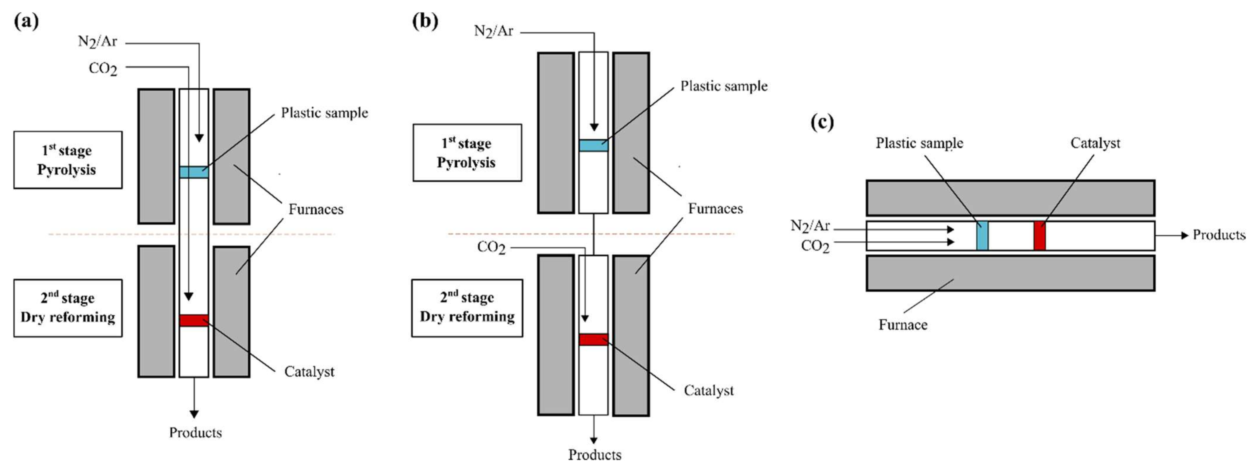
4. Pyrolysis-Catalytic Dry Reforming

Currently, the pyrolysis-catalytic dry reforming (PCDR) process is gaining increasing attention. The process implements the pyrolysis of hydrocarbon sources, such as plastic waste, and the in-line dry reforming of pyrolysis gases in the presence of a catalyst. As a result, high-value-added synthesis gas and liquid chemicals are produced. Three main reactor configuration systems have been already proposed for PCDR processes and tested in the laboratory scale (see Figure 2a–c). The most commonly described are two-stage reactor systems, shown in Figure 2a,b. The first one consists of one tubular reactor divided into two stages, each heated by separate heating units. In the first stage, the pyrolysis process takes place, while in the second stage, the catalytic dry reforming is processed. An inert gas, such as nitrogen or argon, is fed into the first stage to provide an anaerobic atmosphere, while a CO2 stream is fed into the second stage [65,66]. The second two-stage reactor system (Figure 2b) differs by separating the two stages into two tubular reactors [10,12,13,14,15]. Another less common reactor system for PCDR is shown in Figure 2c. In this case, there is only one reactor and heating unit. The hydrocarbon source is pyrolyzed in the presence of CO2, thus, in fact, partial gasification takes place. Then, the mixture of pyrolysis gases, inert gas and carbon dioxide are directly transferred into the catalyst bed, where the dry reforming reaction takes place. In the literature, it is described as a one-stage reactor system [17]. For PCDR processes, the reactors used to date have been fixed bed reactors; however, there are many types of pyrolysis reactors that could potentially be implemented for the first stage of the PCDR process. The different types of pyrolysis reactors are shown in Figure 3 [67]. Reactors are classified depending on how the plastic feedstock is forced to move inside the reactor: pneumatically (fluidized bed reactor and fixed bed reactor), mechanically (auger reactor, rotary reactor, ablative reactor and reactor with stirrer) and gravitationally (column type reactor). Fixed bed reactors are the main type of reactors for large-scale chemical syntheses, used also in laboratory scale configurations for PCDR processes. It is a tube filled with a plastic feedstock with a gaseous stream flowing through the bed and being converted into pyrolytic products. In the fluidized bed reactor, the gaseous stream is passed through a plastic feedstock at speeds that are high enough to suspend the solid and cause it to behave as though it were a fluid [68]. Auger reactors are mechanical reactors where a screw is used to convey the feedstock down the length of a tube [69]. The rotary reactor is a tube inclined slightly on the horizontal position, which is rotated slowly about its longitudinal axis. The feedstock is fed into the upper end of the cylinder and gradually moves down toward the lower end and undergoes mixing [68]. The ablative reactor consists of a chamber, inside of which is a spinning bowl where the feedstock is placed, and a hot plate at the top that moves vertically and applies pressure against the feedstock. The heat is conducted to the plastic feedstock by direct contact with a hot surface, and pyrolysis takes place within a thin layer in contact with the hot surface rather than the entire feed. This provides an opportunity to use large pieces of plastics [70]. The mechanical forces associated with mechanical reactors enhance particle mixing and heat transfer, which are key to successful pyrolysis.
Commonly, PCDR processes proceed at atmospheric pressure and the temperature is different for each stage. The pyrolysis step is carried out in temperature within the range of 673–773 K and DR in the range of 900–1100 K, due to DR reactions being favored in higher temperatures. When the process is carried out in the reactor system that is shown in Figure 2c, the operating temperature is the same for both stages and typically is in the range of 823–1123 K. Pyrolysis-catalytic dry reforming is a promising method in the valorization of waste plastics. By separating pyrolysis and DR, the process is more controllable than conventional one-stage thermo-chemical processes. In addition, pyrolysis solid residues containing contaminants remain in the pyrolysis unit, thus do not affect the catalyst. The gaseous products obtained in the PCDR process are free of tars, and therefore avoid the major problem involving gasification processes [16,71]. The catalysts used to date in PCDR processes are mainly nickel-based catalysts, containing various metals promoters, including Co, Mg, Ce, Cu, Ca, La, Mn, Ru, and Fe, as well as supports, including Al2O3, molecular sieves, activated carbon and zeolites [10,12,17,65]. The most common PCDR catalysts are Ni–Mg/Al2O3 and Ni–Co/Al2O3, due to their high catalytic activity and stability in the dry reforming of hydrocarbons [15,65]. To the best of our knowledge, there are no reports regarding the use of a catalyst in the pyrolysis stage of the PCDR process; only the reforming stage is catalytic.

4.1. Influence of Process Parameters

Product yield and quality heavily depend on numerous variables, including process conditions, type of feedstock, reactor configuration, catalyst type and catalyst:plastic ratio. Active metal, promoter, support and preparation method affect the catalytic activity of the catalyst and carbon deposition. In this section, the influence of those variables over the efficiency of syngas production in PCDR processes is discussed. The list of parameters of pyrolysis processes combined with dry reforming reported in the literature is presented in Table 3.

4.1.1. Feedstock Composition
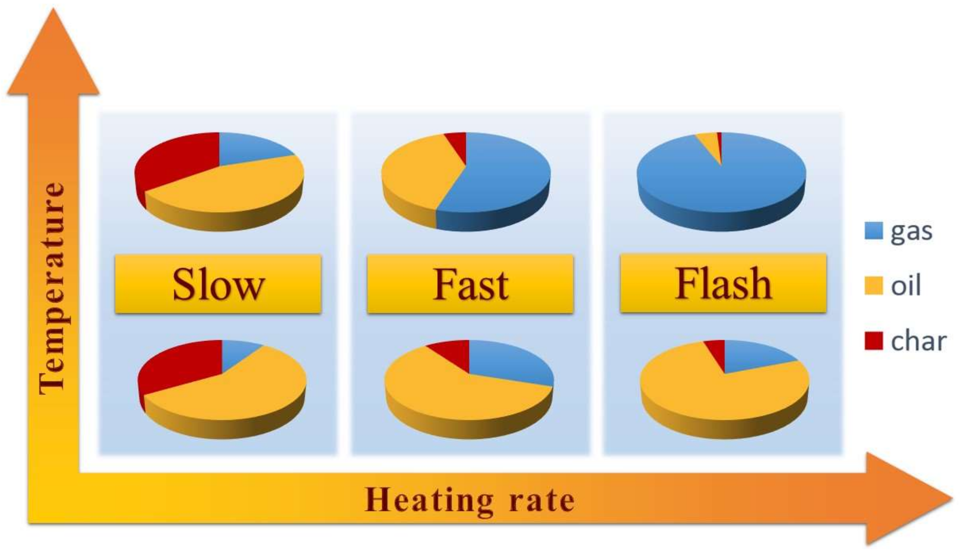
The composition of waste plastic used as a feedstock is of great importance considering the yield and distribution of the products. The chemical structure of the polymer influences the mechanism of thermal degradation at the pyrolysis stage, thus the distribution of the product. Therefore, depending on the polymer raw material and solid residue, the liquid and gas yields will be different [4,73]. Furthermore, the mechanism for the dry reforming of hydrocarbons of varying chain length is quite different. Shah et al. [60] proposed that the mechanism for the C1–C3 hydrocarbon fraction differs from that of the higher hydrocarbons. For C1–C3 alkanes, the dissociation of the carbon–hydrogen bond followed by the oxidation of carbon fragments takes place. The rate controlling step in these cases is the activation of the C–H bonds in the hydrocarbon. Considering higher hydrocarbons, the first step is the direct dehydrogenation of alkanes to alkenes (Equation (3)). The hydrogen formed reacts with carbon dioxide (Equation (4)), thus the equilibrium of the dehydrogenation reaction is shifted. In these cases, the activation of CO2 is the rate controlling step.
CnH2n+2 + nCO2 ⇌ CnH2n + H2
CO2 + H2 ⇌ CO + H2O
The pyrolysis of different waste plastic gives a different distribution of gas, liquid and solid products as well as their compositions. According to the literature[74], alkenes gases represent the small molecular weight range of the scission process coupled with the stabilization of the resultant radical, which leads to the formation of carbon double bonds. Therefore, the pyrolysis of polyalkene plastics, such as PP and PE, leads to the formation of alkenes of the major products. On the other hand, the thermal degradation of PET, which has a high oxygen content, may lead to the formation of CO2 and CO, due to decarboxylation of PET [75]. Moreover, CO may be formed due to the reaction between CO2 and char. Encinar et al. [44] evaluated the products of the pyrolysis of polystyrene (PS), low density polyethylene (LDPE), acrylonitrile butadiene styrene (ABS), polyenterophthalate of ethylene (PET) and polypropylene (PP) at 1073 K under a heating rate of 20 K/min. In addition to the PET, for all plastics, the biggest fraction was composed of liquid/wax, followed by gases and the solid fraction. The two polyalkene plastics (PP and LDPE) produced very similar product yields, with high yields of oil (~79% and ~73%), followed by gas (~21% and ~25%) and negligible char yields. In the case of ABS and PS, the oil yield was also high (~92% and ~95%), but the gas yield was lower (~7% and ~4%), and the char yield was also negligible. During PET pyrolysis, a higher percentage of gases (~59%), followed by wax (~33%), and a significant solid fraction (~8%) are produced. Considering the composition of gases derived from pyrolysis, there are differences between plastics as well. Again, PE and PP were similar in relation to the principal gases formed and they formed mainly ethene and propene. Methane, ethane and propane were also present at lower concentrations. The PS and ABS are the plastics that, subjected to pyrolysis, produce a small quantity of gases. The derived gas consisted mainly of ethene and methane. In the case of PET, much lower concentrations of hydrocarbons are produced, mainly carbon dioxide and carbon monoxide. The results obtained by Encinar et al. [44] are consistent with the results obtained by Williams [45] and co-workers. They studied the pyrolysis of LDPE, PP, PS and PET in similar conditions (heating rate of 25 K/min and temperature of 973 K). It has to be taken into the account that, when the conditions are different, the percentage of the fractions can vary substantially. For example, Mastral et al. [76] carried out the fast pyrolysis of HDPE in various conditions: temperature in the range of 923–1123 K and residence time in the range of 0–2.3 s. In the pyrolysis process at 923 K, HDPE mainly formed liquid products (~76%) and a much lower yield of gaseous products (~24%). In contrast, when the pyrolysis process was carried out at 1123 K, the main products were gases (~87%), followed by liquid products (~14%).
Saad et al. [10] studied the two-stage pyrolysis-catalytic dry reforming of various types of waste plastics (LDPE, HDPE, PS, PET, and PP) over a Ni–Co–Al catalyst. The temperature was 773 K and 1073 K for pyrolysis and dry reforming, respectively. The highest yield of gas products was observed for LDPE (98.3 wt %) and HDPE (94.8 wt %) with no solid residue. In the case of PET, the highest yield of the solid residue equal to 4.0 wt % was noted. The differences in the phases of product distribution resulted from the different PET chemical structures compared to the polyalkene plastics and consequently, the different thermal behavior. This is in agreement with the results obtained by Alvarez et al. [77]. They investigated the co-pyrolysis/gasification of wood sawdust mixtures with different plastics over a Ni/Al2O3 catalyst at 873 K and 1073 K temperatures, for the pyrolysis and gasification steps, respectively. They also reported a high content (5.6 wt %) of solid residue resulting from the pyrolysis–gasification process of the biomass/plastic mixture containing 20 wt % PET. The highest gas and hydrogen production for the pyrolysis-catalytic CO2 reforming of LDPE and HDPE might be due to their high thermal degradation rate during the pyrolysis stage [78]. According to Ray et al. [21], different plastics are characterized by different thermal stability, hence their thermal degradation takes place under different temperature conditions. They reported that the thermal degradation of PP, under a heating rate of 10 K/min in an inert atmosphere, occurred at the temperature of about 623 K, while the thermal degradation of PE and PET occurred above 673 K. Furthermore, it can be concluded that the aliphatic alkanes and alkenes produced during the pyrolysis step are reformed to syngas more easily compared to aromatic compounds, which are the main products of the pyrolysis of PET and PS [16,46]. This is consistent with the data reported by Wu et al. [71], who studied the pyrolysis–gasification of PP, PS and HDPE at temperatures 773 K and 1123 K for the pyrolysis and gasification stage, respectively. Likewise, the highest hydrogen production equal to 0.303 g/gplastic was obtained in the case of HDPE.
The chemical structure of waste plastic affects also the type, formation mechanism and amount of carbon deposited on the catalysts [14,71,79]. Saad and co-workers [8] investigated the properties of coked catalysts using scanning electron microscopy and temperature-programed oxidation. They found that the developed structure of carbon deposits on the surface of each investigated catalyst is strictly dependent on the type of used plastic. The pyrolysis of PP and PS resulted in the deposition of carbon particles with a size within the range of 0.3–0.45 µm and with an oval shape, whereas, in the case of LDPE, a whisker-type structure and a size within the range of 0.15–0.3 µm was observed. In the case of the simulated waste plastic mixture—consisting of 42 wt % LDPE, 20 wt % HDPE, 16 wt % PS, 12 wt % PET, and 10 wt % PP—smaller (below 0.15 µm), more uniform, oval particles were observed. They suggested that, in the case of PS, the layered carbon formation is a result of the reformation of the heavier hydrocarbon compounds derived from the pyrolysis of PS. Wu et al. [71] showed similar results in the pyrolysis–gasification of waste plastics (PP, PS and HDPE). They indicated that more layered carbons were generated when PS was used as feedstock, whereas, for HDPE and PP, mainly filamentous carbons were generated. Filamentous carbon formation is affected and retarded when higher amounts of layered carbon (precursors of filamentous carbons) are generated during the pyrolysis–gasification of PS, which leads to the faster deactivation of the catalyst and, consequently, to a lower syngas and hydrogen production.
Regarding real-world waste plastics, due to their different composition depending on the source of the waste, product distribution and yields may differ. Some of them contain contaminants, such as S, Cl, N and other polymers at lower concentrations, such as polyvinyl chloride (PVC), polyamide (PA) as well as paper, biomass, metals and additives for plastics [80,81]. They may inhibit the process or promote additional coke deposition on the catalyst surface. Saad et al. [14] demonstrated that the pyrolysis-catalytic dry reforming of a wide range of municipal, commercial and industrial waste plastics can be successfully implemented to produce significant amounts of syngas. They demonstrated that a high yield of syngas can be generated from plastic origin, from household waste packaging, building construction sites, agriculture, electrical and electronics equipment waste plants. They carried out PCDR processes over Ni/Al2O3 and Ni–Co/Al2O3 catalysts at the temperatures of 773 K and 1073 K for the pyrolysis and DR stage, respectively. The lowest yield of syngas produced (41 mmol/gplastic) was from refuse-derived fuel, representing processed municipal solid waste mainly composed of plastics, paper, board, wood and textile materials without metals and glass. Carbon deposition during the catalytic dry reforming of plastics from waste refrigerator and freezer equipment (~5 wt %), mixed plastics recovered from old style cathode ray tube television sets and computer monitors (~7 wt %) and plastics from electrical and electronic equipment (~3 wt %) was higher compared to that during the processing of the other types of wastes (<1%). In addition, they indicated that different metal promoters may be required depending on the composition of waste plastics, due to the mixed outcome of the Co promoter in relation to syngas production. For example, in the case of household waste packaging plastics (mainly HDPE and PET), the addition of the Co promoter to the Ni/Al2O3 increased syngas yield from 146.32 mmol/gplastic to 156.45 mmol/gplastic, whereas in the case of plastics originating from agriculture (consisting of HDPE, LDPE and PP), syngas yield decreased from 153.67 mmol/gplastic to 121.26 mmol/gplastic. Considering the effect of contaminants present in real-world waste plastics, Wu et al. [71] observed a lower gas (87.1 wt %) and hydrogen production (0.196 g/gplastic) for the pyrolysis–gasification of municipal solid waste mixed plastic (containing mainly HDPE and PET) compared to PP and HDPE feedstocks. Gas yield was equal to 91.7 wt % and 98.8 wt %, whereas hydrogen production was equal to 0.241 g/gplastic and 0.303 g/gplastic for PP and HDPE, respectively. Moreover, the highest amount of coke formation on the catalyst was observed in the case of real-world waste plastic. It was explained by the deactivation of the catalyst, which resulted from the presence of contaminants and toxic elements, such as Cl, derived from small fractions of polymers, such as polyvinyl chloride, in the waste plastic.

4.1.2. Temperature

Temperature is an important process parameter affecting product yield and distribution, CO2 conversion, H2/CO ratio as well as catalyst activity. The PCDR process requires high temperatures due to the highly endothermic character of the reactions, for example, ΔH = 120–260 kJ/mol for different plastic pyrolysis [82], ΔH = 247 kJ/mol for the DR of methane [83] and ΔH = 170–430 kJ/mol for the DR of ethane [60]. Commonly, PCDR processes involve two different temperatures for the pyrolysis and for the catalytic dry reforming stages. For pyrolysis, the temperature is usually within the range of 673–773 K, while for reforming, it is within the range from 900 to 1100 K [10,12,13,14,15]. There are a few literature reports on PCDR processes carried out under the same temperature conditions for both stages. In this case, the maintained temperature was in the range of 823–1123 K [17,72].
Saad et al. [13] investigated the effect of the catalytic reforming temperature (873 K, 973 K, 1073 K and 1173 K) on synthesis gas production in the two-stage pyrolysis-catalytic dry reforming of waste plastics. The syngas yield increased as the catalyst temperature was raised from 873 K to 1073 K from 116.2 g/gplastic to 148.6 g/gplastic, respectively. CO2 conversion increased from 1.43 g/gplastic to 2.07 g/gplastic. At 1173 K, syngas yield and CO2 conversion decreased to 125.8 g/gplastic and 1.58 g/gplastic, respectively. They also observed the change in H2/CO molar ratio along with the increased process temperature equal to 0.55, 0.48, 0.49, and 0.66 for 873 K, 973 K, 1073 K and 1173 K, respectively. The authors indicated that the reduction in CO yield and increase in H2 yield at 1173 K may be due to the retarding of water gas shift reaction occurring at higher temperatures (Equation (5)). The researchers found that, with increased temperatures, the amount of pyrolysis hydrocarbon gases were reduced from 0.02 g/gplastic to 0.0 g/gplastic for C2–C4 and from 0.08 g/gplastic to 0.01 g/gplastic for CH4. However, simultaneously higher temperatures led to the sintering of the catalyst’s metal active particles. The concentration of carbon deposition was also dependent on the process temperature. The highest carbon deposition on the catalyst (Ni–Co–Al2O3) was observed at the temperature of 1173 K and was equal 5.50 wt.%. They suggested that the greater rate of the hydrocarbon decomposition reaction (Equation (6)), compared to the carbon gasification reaction (Equation (7)), may be the reason behind the carbon build-up on the catalyst surface at 1173 K.
CO2 + H2 → CO + H2O
CmHn → mC + (n/2)H2
C + CO2→ 2CO
Yamada et al. [9] examined the influence of the temperature of the catalyst as well as the temperature of pyrolysis in the PCDR process. They used a two-stage reactor system and the feedstock was polyethylene (PE). The investigated temperature range was of 900–1120 K and 680–720 K for the catalytic and pyrolysis steps, respectively. They observed that syngas yield increased with the increase in catalyst temperature and PE was completely reformed to CO and H2, when the catalyst temperature was 1120 K. Considering the effect of pyrolysis temperature on the PCDR process, they reported that a temperature higher than 680 K negatively affected syngas yield, due to the excessively high thermal decomposition rate of the polymers and the reaction on catalyst surface being too slow to reform all reactants to CO and H2. Lowering the pyrolysis temperature to 680 K resulted in a low pyrolysis rate, thus a low rate of reagents was supplied into the catalyst bed. Therefore, the time factor at the catalyst bed was increased and the pyrolysis products were completely converted to H2 and CO. However, a long time was required for the consumption of all the PE.
Al-Asadi et al. [17] studied the dry reforming of the mixture of real-world waste polymers (LDPE, HDPE, PP and PET) in a one-stage horizontal reactor into syngas. They carried out the processes at 823 K and 1123 K over Ni/ZSM-5 catalysts with different metal promoters (Ca, Ce, La, Mg and Mn). The results showed that the syngas yield increases with the increase in the reaction temperature. The average syngas yield for all catalysts was 57.1 mmol/g and 113.4 mmol/g for 823 K and 1123 K, respectively. A higher temperature favors the more intensive cracking of the C–C bond, leading to the dominant formation of gases over other pyrolysis phases. Moreover, the increase in syngas yields under 1123 K was attributed to the dry reforming reaction, which requires a high temperature to occur. Considering the carbon deposition on the catalyst surface, the authors demonstrated that the temperature increase to 1123 K resulted in the decreasing in the carbon deposited yields, from 11–17% to 5–7%, due to its gasification by CO2. These results are in accordance with another work of Al-Asadi and co-workers [72], in which they also investigated the dry reforming of waste polymers in a one-stage horizontal reactor over the same catalysts, but CO2 was produced in situ using dolomite. Again, increasing the temperature from 823 K to 1123 K enhanced syngas yield and decreased carbon deposition on the catalyst. The average syngas yield for all the catalysts in the presence of dolomite was 12.3 mmol/g and 102.7 mmol/g for 823 K and 1123 K, respectively. When they carried out the process without dolomite, the average syngas production was 11.8 mmol/g and 64.8 mmol/g for 823 K and 1123 K, respectively. This means that the dolomite presence did not affect significantly the gas formation at 823 K. In addition, the higher pyrolysis temperature led to a lower amount of deposited carbon on the catalyst surface, which was in the range of 12–16% at 823 K and decreased to a range of 6–10% at 1123 K.

4.1.3. Catalysts

Catalysts play a key role in the process of the pyrolysis-catalytic dry reforming of waste plastics, thus requiring an optimum design. Nickel-based catalysts are the most common catalysts used for syngas production from plastics by thermo-chemical conversion and are considered to be the most viable catalysts due to their high activity, selectivity, stability and competitively low cost [60,84,85]. Nickel-based catalysts show high efficiency in the catalytic dry reforming of pyrolysis gases due to their higher capacity to break C–C chemical bonds, which results in the high amounts of hydrogen produced [86]. The beneficial properties of nickel-based catalysts are affected by many parameters, including co-catalysts, promoters and the support. Their structure and properties affect the size and shape of Ni particles. The effect of co-catalysts, promoters and the support properties result from the enhancement or deterioration of the Ni dispersion stability through affecting the metal active-support interactions, nucleation and particle’s formation. Moreover, the introduction of additives to the nickel catalysts may retard or improve the catalysts’ properties, such as basicity and mechanical properties. To date, many types of nickel-based catalysts have been investigated. Al2O3 [13,15,66] and ZSM-5 [17,72] have been used as supports. Co, Mg, Cu, Ru, Ca, Ce, La and Mn have been examined as promoter and co-catalysts [12,14,15,65]. The list of the selected catalyst examined in PCDR processes is shown in Table 2.
The method of catalyst preparation influences its physicochemical properties, thus catalytic activity and stability. The preparation of the catalyst via a suitable method can result in a higher surface area, better particle dispersion and stronger metal–support interaction, which are factors responsible for high activity, stability and resistance against carbon formation and sintering [55]. The conventional catalysts for dry reforming processes are mainly prepared by several methods, including sol–gel, impregnation and co-precipitation [53]. Saad et al. [13] compared the effect of two methods of Ni–Co–Al2O3 catalyst preparation, the co-precipitation technique and the impregnation technique, on its performance in the dry reforming of waste plastics. The co-precipitation method involved the dissolution of Co(NO3)2·6H2O, Ni(NO3)2·6H2O and Al(NO3)3·9H2O in deionized water at 40 °C, and the addition of 1 M ammonium solution to pH 8.3 until the precipitate was formed. The impregnation method involved the dissolution of Ni(NO3)2·6H2O in deionized water at 80 °C, the addition of Co(NO3)2·6H2O and, after 30 min, the addition of γ-Al2O3 to form a slurry. Both precipitates were filtered, dried, and then calcined at a temperature of 750 °C for 3 h. All the catalysts were crushed and screened to a particle size in the range of 50–212 µm. An increase of 17% of the synthesis gas yield was achieved from the experiment with the catalyst prepared by the co-precipitation technique compared to the preparation via the impregnation method. On the other hand, they observed a slightly increased carbon deposition on the catalyst prepared via the co-precipitation technique (1.7 wt %) compared to the catalyst prepared via the impregnation technique (1.5 wt %). Aghamohammadi et al. [87] conducted a similar research comparing the catalyst Ni/Al2O3–CeO2 prepared by the sol–gel and impregnation methods for the dry reforming of methane. The preparation of the catalyst via the impregnation method involved two steps: the first step was ceria doping over alumina and the second step was the addition of Ni to the composite support of Al2O3–CeO2. In the first step, Ce(NO3)3·6H2O and γ-Al2O3 were added to deionized water to prepare a sample with 10 wt % of CeO2 in the support. The obtained sample was stirred for 5 h at 60 °C. The composite Al2O3–CeO2 material was collected via filtration and dried at 110 °C for 12 h followed by calcination at 550 °C for 4 h. In the second step, the synthesized support was impregnated with an aqueous solution of Ni(NO3)2, while stirring for 5 h at 60 °C to yield 10 wt % Ni on the Al2O3–CeO2 support. The solid was filtered and dried at 110 °C for 12 h followed by calcination at 550 °C for 4 h. For the synthesis of the Ni/Al2O3–CeO2 catalyst via the sol–gel method, appropriate proportions of Al and Ce precursors were separately dissolved in deionized water at 60 °C for 5 h, followed by the addition of the Ni precursor as an active phase and by stirring for another 5 h. During the synthesis, citric acid as gelling agent was added drop wise into the solution under continuously stirring. After this, the mixture was held in a water bath at 65 °C to form a wet gel. The obtained gel was dried at 110 °C for 12 h and calcined for 6 h at 550 °C under static air. They reported a higher distribution of the active phase with a smaller particle size (average particle size of 35.9 nm) in the sol–gel method than the impregnation method (average particle size of 55.7 nm), which resulted in an enhanced catalytic performance. The dry reforming of methane at 1023 K over the catalyst prepared via the impregnation method resulted in an 18% H2 yield and a 28% CO yield. When the catalyst prepared via the sol–gel method was used, the H2 yield increased to 84%, whereas the CO yield increased to 90%. Moreover, the CH4 conversion was equal to 90% and 35% for the catalyst prepared via the sol–gel method and the impregnation method, respectively.
The introduction of promoters, such as Co, Mg, Ce, and Ru, to nickel catalysts may improve stability and catalytic activity by improving the physical and chemical properties [12,15,17,66,88]. Moreover, a better structure and uniformity of the catalyst particles can be obtained by adding metal promoters, which improve the metal dispersion. Al-Asadi et al. [17] studied the effect of the addition of different catalyst promoters (Ca, Ce, La, Mg and Mn) on a Ni-based catalyst in the pyrolysis dry reforming of waste plastic mixtures (HDPE, PP and PET). They demonstrated that the composition of the catalysts affects the composition of the products, for example, they increase the yields of gaseous products or promote isomerization, cyclization and aromatization reactions. The results showed that, among the other catalysts, Ce/Ni/ZSM-5 had the highest syngas yields equal to 61.1 mmol/g and 132.0 mmol/g at 823 K and 1123 K, respectively. The relation of syngas yields for the Ni/ZSM-5 catalyst with other metal promoters at 823 K were as follows: Ca (58.0 mmol/g) > Mn (57.4 mmol/g) > La (53.7 mmol/g) > Mg (51.9 mmol/g). At 1123 K, the relation of syngas yields for different metal promoters was quite different: La (119.2 mmol/g) > Ca (112.2 mmol/g) > Mg (103.8 mmol/g) > Mn (100.3 mmol/g). Moreover, Ren et al. [88] reported that a Ni-based catalyst modified by Ce exhibited excellent anti-coking ability and stability due to the presence of Ce, promoting coke elimination. Saad et al. [65] studied the catalytic performances of nickel-based catalysts modified by Cu, Mg and Co in the CO2 reforming of HDPE at 1073 K. The addition of the Mg and Co metal promoters to the Ni–Al catalyst increased the syngas production from 138.81 mmol/g to 146.96 mmol/g and 149.42 mmol/g, respectively. However, the Cu metal promoter reduced the syngas production to 130.56 mmol/g, which was attributed to the very weak Cu metal–support interaction, resulting in a low catalytic activity. The Ni–Co–Al catalyst performed the highest CO2 conversion (58%) compared to the Ni–Cu–Al (46%) and Ni–Mg–Al (52%) catalysts. The CO2 conversion for the Ni–Al catalyst was equal to 54%. They also observed the reduction in the carbon deposited on the catalyst surface after the catalytic process for the Co-modified catalyst from 1.0 wt % to 0.0 wt %. Furthermore, the investigation of the effect of the Co concentration showed that the higher the Co content, the higher the CO2 conversion and syngas production. Along with the increment in cobalt content from 25 wt % to 50 wt %, the syngas yield was enhanced from 139.74 mmol/g to 155.13 mmol/g, respectively. The promotional effect of cobalt as a promoter/cocatalyst was reported by [56,64,89,90]. The improved activity was attributed to the strengthening of the metal–support interaction. Other metals, such as magnesium, have been reported to exhibit a higher activity compared to cobalt. Saad et al. [15] investigated pyrolysis dry reforming combined with steam addition over Ni–Mg–Al and Ni–Co–Al catalysts. For the Ni–Mg–Al catalyst, a higher syngas yield (146 mmol/g) was observed than for Ni–Co–Al (135 mmol/g) within a CO2/steam ratio of 4:1. In addition, the H2/CO molar ratio was higher for Ni–Mg–Al, which was equal to 1.41, whereas for Ni–Co–Mg, it was equal to 0.94. The authors concluded that the Ni–Mg–Al catalyst promotes the process towards the steam reforming (Equation (8)) and water gas shift (Equation (9)) reactions and the Ni–Co–Al catalyst promotes the process towards the dry reforming reaction (Equation (10)) and the Boudouard reaction (Equation (11)).
CnHm + nH2O → nCO + (n + m/2)H2
CO + H2O → CO2 + H2
CxHy + xCO2 → 2xCO + y/2H2
C + CO2 → 2CO
Noble metal catalysts were also investigated to promote dry reforming processes [48,54,55,59,60]. The attractiveness of the noble-metal-based catalysts results from their high resistance to coke deposition, stability and high catalytic activity. Noble metal particles are not susceptible to sintering and thus provide a high dispersion. Moreover, they retard the formation of coke. Therefore, there is a significant difference in the performance of the noble-metal-based catalysts compared to their non-noble counterparts. However, the use of noble-metal-based catalysts is hindered by their high cost and limited availability. In this regard, alloy catalysts are preferable for industrial uses, where noble metals are added to the primary metal, which enhances the properties of the catalyst, while maintaining a comparatively low price. Younis et al. [12] performed the dry reforming of polypropylene over RuNi/Al2O3 catalysts. The addition of a small amount of ruthenium (1 wt %) as a metal promoter to the Ni/Al2O3 catalyst (15 wt % Ni) enhanced the production of hydrogen from 0.03 mol/g to 0.04 mol/g. In addition, they indicated that the promoted catalyst with Ru is less prone to deactivation since less carbon is deposited on the catalyst surface in the presence of Ru (4 wt %) compared to the Ni/Al2O3 catalyst without the promoter (6 wt %). Yamada et al. [9] evaluated the effect of Pd/Al2O3 for the pyrolysis dry reforming of polyethylene. In the case of the dry reforming stage carried out at 910 K, the addition of the catalyst increased the hydrogen and carbon monoxide yields, from 1.7% to 35.4% and from 0% to 24.5%, respectively. When the temperature was increased to 1120 K, the polyethylene was completely reformed to CO and H2.
Transition metal carbide (TMC) catalysts are attracting increasing attention in DRH processes due to their high catalytic activity and thermal stability [63,91,92,93,94,95]. The molybdenum and tungsten carbides have very comparable catalytic activity to the noble metal catalysts and are stable at elevated pressures. Furthermore, TMCs are attractive due to their ability to prevent carbon deposition on the catalyst surface in the dry reforming process, due to the reaction mechanism based on carburization–oxidation cycles. In the dry reforming of methane, carbon dioxide is reduced to carbon monoxide with the simultaneous oxidation of carbide to metal oxide, followed by carburization, in which carbon atoms are obtained from methane cracking and carbon monoxide disproportionation. Therefore, the formation of carbon deposits on the catalyst surface is inhibited. The most commonly used carbide catalyst in the dry reforming of hydrocarbons is Mo2C. Brungs et al. [96] studied the dry reforming of methane at an elevated pressure over the supported Mo2C catalysts. The results showed that the relation in the stability of the catalysts is as follows: Mo2C/Al2O3 > Mo2C/ZrO2 > Mo2C/SiO2 > Mo2C/TiO2. The highest conversion of methane was in the case of the Mo2C catalyst supported on SiO2, followed by Mo2C/ZrO2, which reached 91% and 90%, respectively. Although both Mo2C/SiO2 and Mo2C/ZrO2 lead to the higher conversion of methane, Mo2C/γ–Al2O3, unlike them, showed no appreciable sign of deactivation after dry reforming for 40 h, with a conversion of methane close to 90%. On the other hand, the catalytic properties of tungsten carbide are similar to those of platinum catalysts, but its cost is much lower. Therefore, WC is widely studied for use in catalysis research, due to its potential to reduce the cost of the process by partially or completely replacing noble metals. Moreover, the literature reports indicate that WC catalysts are highly resistant to acid solutions and to CO poisoning, which results in a longer catalytic life [97,98]. However, attention should be paid to the fact that, at atmospheric pressure, metal carbide catalysts tend to deactivation due to CO2 oxidation of MxC to MO2. Therefore, with the aim to improve the catalytic properties of metal carbides, the addition of metals, such as Ni, Co and Fe, was investigated [89,91,99,100,101]. Guo et al. [95] fabricated a catalyst composed of metallic nickel and molybdenum carbide for the CO2 reforming of CH4. They demonstrated that the Ni–Mo2C catalyst is superior to conventional metal carbide catalysts as verified by its stable activity at atmospheric pressure. The role of Ni is to enhance the dissociation of CH4 for the regeneration of Mo2C. In the established unique oxidation and carburization cycle, MoO2 is carburized back to Mo2C, allowing for its stable performance. Zhang et al. [102] investigated the catalytic activity of the Ni–WCx catalysts for the DRM reaction at atmospheric pressure. Similarly, they demonstrated that Ni-modified WCx are active and stable catalysts for the DRM reaction. In addition, Lalsare and co-workers reported that the modification of the Mo2C catalyst with Fe results in enhanced catalyst stability and a better particle size distribution [100].
To the best of our knowledge, there are no reports regarding the use of transition metal carbide catalysts in the processes of the pyrolysis-catalytic dry reforming of plastics. TMC have great potential as catalysts in this area, due to their catalytic activity in the dry reforming not only of methane, but also of other hydrocarbons. TMC-based catalysts have been investigated in the dry reforming of ethane [103], propane [50,104] and butane [105]. The dry reforming of ethane (DRE) proceeds through the reduction of ethane and oxidative dehydrogenation (ODH), leading to the formation of ethylene, as presented in Equations (12) and (13) [103]:
C2H6 + 2CO2 = 4CO + 3H2
C2H6 + CO2 → C2H4 + CO + 3H2O
Porosoff et al. [103] investigated the Mo2C/Al2O3 catalyst in the dry reforming of ethane. They reported that the catalyst promoted the formation of ethylene, rather than the production of syngas through the DRE path. For propane, ODH processes are illustrated by Equations (14)–(18). CO2 oxidizes the surface of the TMC catalysts to produce oxycarbides. Propane forms a surface complex with the active oxygen from oxycarbide (Equation (14)), then the C–H bond is broken in the reduced centers (Equation (15)) or another active oxygen (Equation (16)). As a result, mainly propylene is formed.
C3H8(g) + O(a) ↔ C3H8O(g)
C3H8O(a) = C3H7O(g) + H(a)
C3H8O(a) + O(a) ↔ C3H7O(g) + OH(a)
C3H7O(a) = C3H6(g) + OH(a)
2OH(a) = H2O(g) + O(a)
Ronda-Lloret et al. [105] reported the catalytic activity of Co3O4/Ti2AlC in the dry reforming of butane. The level of butane conversion was 20% after 18 h of testing. The efficiency of the butane conversion was higher compared to Co3O4/TiO2, which exhibited only 5%. However, it was lower than that for Co3O4/Al2O3 (42%). Despite the lower activity, the Co3O4/Ti2AlC catalyst exhibited a higher stability and anticoking properties compared to the metal oxide-supported catalysts.
Deactivation and the possibility of regeneration of the deactivated catalyst is an important aspect of PCDR processes. Catalyst deactivation can occur by series of physicochemical phenomena, including metal sintering, metallic phase oxidation, the thermal degradation of the support and coke deposition [106]. The type of deactivation depends on the catalyst composition, structure, feedstock and operating conditions. The catalyst regeneration strategy involves reaction/regeneration cycles. The common way to regenerate a catalyst is to use an oxidizing medium at high temperatures, which causes the coke to burn out. According to the literature [107,108], Ni-based catalysts do not fully recover their activity after the first reaction/regeneration cycle, but, after several cycles, the sintering of Ni particles no longer occurs; hence, the catalysts gain more stability. Moreover, a more stable behavior during the reaction/regeneration cycles of Ni-based catalysts can be achieved by using spinel-like NiAl2O4, alloys of Ni–Fe or by incorporating compounds to support basicity regulation, such as MgO, CeO2, and MnO, to the Ni-supported catalyst [109,110,111].

4.1.4. Catalyst-to-Plastic-Feedstock Ratio

The ratio of catalyst to plastic feedstock is another important factor that affects the selectivity and yields of PCDR. From the point of view of the potential implementation of PCDR technology, efforts should be made to minimize the amount of catalyst in relation to plastic. There are few reports investigating the influence of the catalyst-to-plastic-feedstock ratio and its effect on syngas production for the pyrolysis dry reforming of waste plastics. Saad et al. [13] studied the catalyst:plastic ratios of 0.25, 0.5, 1.0 and 1.5 in the pyrolysis-catalytic dry reforming of simulated waste plastic mixtures (42 wt % LDPE, 20 wt % HDPE, 16 wt % PS, 12 wt % PET, and 10 wt % PP). The syngas yield gradually increased from 141.3 mmol/gplastic for a ratio equal 0.25 to 148.6 mmol/gplastic with a Ni–Co–Al2O3-to-plastic ratio of 0.5, followed by a slight decrease to 139.9 mmol/gplastic as the catalyst:plastic ratio was increased to 1.5. The addition of the catalyst reduced the deposition of carbon from 5.5 wt.% to 1.8 wt.% at a catalyst-to-plastic ratio of 0.25, which steadily decreased to 1.7 wt.% at a catalyst:plastic ratio of 0.5. Further increasing the catalyst:plastic ratio resulted in no carbon deposition on the catalyst surface. It was suggested that the additional loading of the catalyst allows for more pyrolysis gases to react with the catalyst, resulting in a lower carbon deposition on the catalyst and a higher gas production. Wu and Williams [112] reported that increasing the Ni–CeO2–Al2O3-catalyst-to-plastic ratio (0.25–2.0) resulted in an increased production of hydrogen from 48 wt % to 62 wt % in the catalytic reforming of polypropylene. However, in another work by Wu and Williams, no significant difference was observed upon increasing the catalyst:plastic ratio of the Ni–Mg–Al catalyst between the range 0.5 and 2.0 in the pyrolysis-catalytic steam reforming of municipal solid-waste-derived plastic [113]. It was assumed that a 0.5 catalyst:plastic ratio is adequate enough due to the effective catalytic activity of the Ni–Mg–Al catalyst. Wu et al. [114] investigated the effect of the catalyst:plastic ratio (1.0–3.0) in the pyrolysis–gasification of polyethylene plastic waste into hydrogen. Similarly, they demonstrated that 0.5 g of the Ni–Ce@SiO2 catalyst is effective enough per 0.5 g waste plastics. In addition, they found that increasing the loading of the catalyst in a range of 1.0–3.0 resulted in a slight drop (~5%) of H2 yield. This was attributed to the aggregation of the catalyst under high temperature conditions.
It should be noted that, in the above-mentioned works on PCDR processes, the catalyst/plastic ratio is considered as a continuous catalyst feed. Taking into account the fact that a given amount of catalyst can be used multiple times, while only the plastic feed is replaced by the subsequent amount, the process costs can vary significantly. Therefore, additional studies on the reuse and stability of the catalysts as well as possibility of their regeneration are necessary.

4.1.5. Steam Addition

Currently, the combination of dry and steam reforming is gaining increasing attention. The interest of the combined process lies in the results from the higher efficiency of the H2 production, thus a higher H2/CO ratio, which is the key factor in syngas quality [52,115,116] and the possibility to control the composition of the outlet stream. Moreover, the steam in the inlet gas can result in a decrease in the carbon deposition on the catalyst surface due to the gasification of coke, and therefore it allows to avoid the major problem involving catalyst deactivation [117]. The H2/CO ratio of synthesis gas is of significant importance in regard to the end-use application, due to different products requiring syngas with different H2 and CO content. Song and Guo [52] described a wide range of possible syntheses using syngas with different H2/CO ratios, including the production of liquid fuels through the Fischer–Tropsch process, the production of methanol through catalytic reactions with syngas and the production of various aldehydes and alcohols via the hydroformylation reaction. According to their study, for Fischer–Tropsch syntheses, the desirable syngas composition is best characterized by a H2/CO ratio of about 2.0, but for the hydroformylation reaction, the optimum H2/CO ratio is around 1.0. Synthetic gas, rich in hydrogen, with a H2/CO ratio equal to 3 or greater, is dedicated for processes that require high contents of H2, e.g., ammonia synthesis. The required H2/CO ratios of synthesis gas for selected products are summarized in Table 4.
As shown in Table 3, in the pyrolysis-catalytic dry reforming of waste plastics, depending on the process conditions, catalyst and feedstock, syngas with different H2/CO ratios can be obtained. However, in most of the presented results, the H2/CO ratio is less than the unity, thus the product of the dry reforming of waste plastics should be dedicated to units in which a carbon-monoxide-rich substrate is needed. For applications of syngas with a higher H2/CO ratio, the supplemental addition of H2 would be required to adjust the H2/CO ratio or, instead, the addition of steam in the feed gas. Feeding the inlet gas with the appropriate CO2/H2O ratio to the reforming unit is a promising approach for controllable redeeming units. There are many investigations on the beneficial effects of steam addition on product yields and the reduction in the carbon deposition on the surface of the catalyst. When steam is introduced into the dry reforming system, both the steam and dry reforming reactions (Equations (19) and (20)) occur simultaneously [120]. In addition, the H2 production is also improved due to steam enhancing the water–gas shift (Equation (21)) equilibrium [16]. In general, the kinetics associated with the steam reforming reaction are more favorable compared to the dry reforming reaction [60]. CO2 and H2O compete for the same adsorption sites. Guilhaume et al. [120] in their work reporting combined reforming, reported that, at high temperatures, the surface of the Ni–Rh/MgAl2O4 catalyst was covered mainly by strongly adsorbed H2O species. The introduction of steam into the system in a non-stoichiometric quantity allows to manipulate the H2/CO molar ratio. Furthermore, steam may also act as a char gasifier in the reforming process. Char steam gasification (Equation (22)) kinetics is between two and five times faster than under a CO2 atmosphere (Equation (23)), thus the enhanced reduction in carbon deposition under steam input [117].
CnHm + nH2O → nCO + (n + m/2)H2
CxHy + xCO2 → 2xCO + y/2H2
H2O + CO ⇌ H2 + CO2
C + H2O → CO + H2
C + CO2 → 2CO
Saad et al. [15] investigated a range of different CO2/steam ratios of the inlet gas for the pyrolysis-catalytic reforming of a mixture of plastics: 4:0, 4:0.5, 4:1, 4:1.5 and 4:2 for the Ni–Co/Al2O3 catalyst and 4:0, 4:0.5, 4:1, 4:2 and 4:3 for the Ni–Mg/Al2O3 catalyst. Their results showed that, by manipulating the CO2/steam input ratio, the syngas H2/CO ratio can be manipulated between 0.74 and 0.94 for the Ni–Co/Al2O3 catalyst and between 0.6 and 1.4 for the Ni–Mg/Al2O3 catalyst. The optimum CO2/steam ratio was observed at 4:1 for both catalysts due to the highest H2/CO molar with an acceptable syngas yield at 133.87 mmolsyngasg−1plastic for Ni–Co/Al2O3 and 146 mmolsyngasg−1plastic for Ni–Mg/Al2O3. Moreover, they observed a decrease in the carbon deposited on the catalyst from 23.50 wt%, in the experiment without steam addition, to 0.50 wt% at the CO2/steam ratio of 4:2. Increasing the reduction in carbon deposits on the catalyst with the increase in the steam content in inlet gas indicates that a carbon gasification with steam occurred (Equation (22)).
In another work, Saad and co-workers [66] carried out further investigations on syngas production from the non-catalytic pyrolysis dry reforming of HDPE with the addition of steam. Carbon dioxide and steam were introduced to the system at different CO2:H2O ratios: 1:0, 3:1 and 1:3. Similarly, the addition of steam enhanced hydrogen production and reduced carbon deposition. The highest amount of hydrogen produced and the lowest carbon deposition was achieved at a CO2:H2O ratio of 1:3 and was 66.47 mmol/gplastic and 0.11 g/gplastic, respectively. The addition of steam to the non-catalytic system also resulted in high amounts hydrocarbons, such as methane, which increased with further steam addition. They suggested that the addition of steam may affect the reaction conditions inside the reactor and may consume some energy in the reactor, hence limiting the hydrocarbon-cracking efficiency. It is in accordance with the results obtained by Wu and co-workers [71], in which the hydrocarbon concentration of the non-catalytic pyrolysis–gasification of HDPE was higher when steam was introduced. However, with the addition of the Ni–Mg–Al catalyst in that study, the efficiency of the cracking of methane and other hydrocarbons was enhanced and resulted in lower concentrations of hydrocarbons and a higher hydrogen yield.
According to Wysocka et al. [115], the addition of steam in the combined reforming of methane resulted in a higher efficiency of hydrogen production as well, thus a higher H2:CO ratio. The introduction of a feed composition CH4:CO2:H2O = 1:0.8:0.4 and CH4:CO2:H2O = 1:0.6:0.6 resulted in an increase in the average value of hydrogen-to-carbon-monoxide ratio to about 1.5, while CH4:CO2:H2O = 1:0.4:0.8 resulted in a H2:CO ratio of around 2. On the other hand, combined reforming resulted in a lower CO2 conversion compared to dry reforming. A similar tendency was also reported in the previously mentioned works regarding the pyrolysis-catalytic dry reforming of waste plastics [15,66].

4.2. The Strategies and Challenge on Carbon Disposal

Scaling up the PCDR process always brings with it additional challenges, such as the need to manage waste. One of the main challenges in the plant scale is the post-process carbon disposal. The main product of PCDR processes is synthesis gas; however, depending on the process parameters, by-products, such as liquid oil or char, can be formed. These products can also be valuable, so, on an industrial scale, their separation and further use should be considered.
Liquid oil generated in the pyrolysis of waste plastics, which is rich in liquid hydrocarbons (aromatic, olefin, and naphthalene), can be used as a recovered resource in energy-related applications, such as heating purposes, electricity generation, transportation fuel or feedstock for the generation of chemicals. Miandad et al. [73] studied the conversion of different types of plastic waste (PS, PE, PP and PET) into valuable liquid oil via pyrolysis process. The obtained liquid oil had higher heating values (HHV) in the range of 41.7–44.2 MJ/kg, which is close to conventional diesel. Therefore, the liquid oil generated in the PCDR process could be used as an alternative energy source and as transportation fuel after refining/blending with conventional fuels. Nileshkumar et al. [121] used plastic pyrolysis oil generated from waste HDPE, LDPE and PP as transportation fuel after mixing it with diesel fuel. They concluded that a blend containing 20 vol. % of pyrolytic oil exhibited an engine performance equivalent to conventional diesel fuel. Rehan et al. [122] proposed the application of the liquid oil generated in the pyrolysis of municipal plastic waste as fuel in a diesel engine to produce electrical energy, due to its similar characteristics to conventional diesel (density 0.8 kg/m3, viscosity up to 2.96 mm2/s, flash point 30.5 °C and energy content 40 MJ/kg). Saptoadi et al. [123] demonstrated that plastic waste (PE, PP, PS, and PET)-derived oil can be used as a partial substitute for kerosene in pressurized cookstoves. They indicated that the thermal efficiency of pyrolytic oils blended with kerosene in a volumetric ratio of 1:3 do not differ significantly (~3%) from pure kerosene. Furthermore, liquid oil can be also processed to recover chemicals, such as styrene, benzene, toluene or polymeric monomers, which can be transferred to an established market [124].
A solid by-product that remains after the pyrolysis stage is char. Char also has a wide list of its potential applications: adsorbent in the water treatment [125], activated carbon production [126], reducing agent [127], fuel briquettes [128], raw materials for fabrication of graphene [124], supercapacitors [129], nanocatalysts and nanofillers for composite applications [130].
An important aspect that should be taken into account is also the composition of the synthesis gas obtained in the PCDR processes. According to the literature reports on PCDR processes summarized in Table 3, the obtained synthesis gas was rich in carbon monoxide (H2/CO ratio around 1). Therefore, as obtained, syngas is suitable for several processes, such as the synthesis of dimethyl ether or oxo-synthesis process in aldehyde and alcohol production [52,119]. If the synthesis gas produced were to be used in processes requiring a higher content of hydrogen, such as methanol production or the Fisher–Tropsch syntheses, the strategy discussed in Section 4.1.5 involving the addition of steam to the input stream could be followed, resulting in a higher H2/CO ratio. On an industrial scale, it is also worth implementing stream recirculation, which would allow to maximize the use of carbon dioxide feedstock and enhance the efficiency of synthesis gas production.

5. Concluding Remarks and Prospects

In recent years, the pyrolysis-catalytic dry reforming of waste plastic to syngas has gained more attention and is increasingly being advanced, as regard to environment considerations in terms of emissions of CO2 and waste management. It is well known that syngas can then serve as a feedstock for further chemical processes, such as in the Fischer–Tropsch synthesis, to produce a number of subsequent chemical products and fuels.
In this work, we discussed the influence of many process parameters, such as operating conditions, catalyst, feedstock on the efficiency of the PCDR (pyrolysis-catalytic dry reforming) process, and their optimization is a challenge for further research. Despite the variability of the studies, a joint analysis of the results allows to establish the state of the art in relation to the process variables studied. The type of feedstock is of great importance as, depending on its composition and the chemical structure of constituents, different product distribution and composition can be obtained, as well as it may affect carbon deposition on the catalyst. In general, it was found that the pyrolysis of polyalkene plastics mainly leads to the formation of alkenes, such as ethene and propene; PET generates a high amount of gaseous fraction, composed mainly of CO2 and CO due to its high oxygen content, while PS forms a high liquid fraction composed mainly of styrene. In PCDR processes, LDPE and HDPE were found to produce the highest content of gaseous products and the solid residue is negligible. PET, due to its different thermal behavior, generates relatively high amounts of solid residues compared to polyalkene plastics. Moreover, from the same raw material, different products depending on the thermal degradation conditions, such as temperature, heating rate or residue time, are produced. Gaseous products have been found to be favored under conditions of higher temperature and higher heating rate, while under conditions of lower temperature and lower heating rate, more liquid and solid products are produced. In the available reports on PCDR, there are no comprehensive studies on the conversion of a specific type of polymer waste in a wide range of conditions and the impact on the obtained product to date. No attempts were made to apply the conditions corresponding to fast/flash pyrolysis in PCDR, which according to the literature, may allow to obtain a greater partition of gases in the pyrolysis stage. Thus, future studies should also be conducted to understand the impact of pyrolysis technology in PCDR on the various output products. Furthermore, the type of plastic feedstock affects the type and amount of carbon deposited on the catalysts, hence its deactivation. The deactivation of the catalyst due to carbon deposition regards mainly PS feedstock. The pyrolysis of PS generates heavier hydrocarbon compounds, and their reformation results in the formation of layered carbon, which leads to the faster deactivation of the catalyst than the filamentous carbon formed in the case of polyalkene plastics. In addition, few researchers used real plastic waste in their research. Instead, pure plastics or simulated mixtures were used. It should be noted that real wastes are not free of various contaminants and have diverse compositions, which may adversely affect the quality of the obtained synthesis gas. Hence, the scope of further research should also be expanded to include real wastes.
Mainly nickel-based catalysts have been used to date in PCDR processes; however, there is a need to overcome the problem of catalyst deactivation while maintaining a high catalytic activity. Considering industrial applications and the commercialization of syngas production via the pyrolysis-catalytic dry reforming process, it is necessary to develop cheap and robust catalysts with a high performance and long-term stability. The properties exhibited by catalysts depend strictly on the extent and manner with which its constituent components interact with one another. In this regard, it is imperative to conduct in-depth research on the synergistic interactions of catalyst components, such as active sites, basicity and metal–support interactions. The strong interactions between metal and support, metal and promoter and other components of the catalyst are crucial for the enhanced catalytic activity and resistance towards deactivation at high reaction temperatures. Understanding these interactions will allow the production of catalysts with requisite selectivity, stability and conversions. In addition, there is insufficiently little research into the catalyst:plastic ratio and the possibilities of regeneration of catalysts; hence, it is also an important area for further research.
Typically, the synthesis gas obtained in the PCDR process of waste plastics has a H2/CO ratio of less than the unity, which is unsuitable from the perspective of its industrial application. Therefore, researchers should seek for new methods to improve the quality of the produced syngas. Recently, the combination of dry reforming with the addition of steam has been attempted and a positive impact on the H2/CO ratio was reported. Moreover, the presence of steam had a positive effect on the efficiency of the process and the carbon deposition on the catalyst was reduced.
Overall, despite the promising potential of conversion waste plastics in pyrolysis-catalytic dry reforming and the reported successful attempts to produce high-quality syngas, this is still an under-explored area. As mentioned earlier, many process parameters require more detailed investigation to optimize the process further. Moreover, the implementation of PCDR processes on an industrial scale includes the demand to obtain high yields and product quality, while maintaining a low cost of the process. PCDR processes are highly endothermic, thus a high energy demand can be considered as another challenge for researchers, who should search for attempts to reduce it, for example, by properly designed catalysts, which can lower activation energy of the reaction.
In conclusion, this review provides the starting point for further research on PCDR processes and developments in these technologies may emerge as a promising and sustainable approach to address the growing requirements for the management of plastic waste and new opportunities for environmental protection by the utilization of one of the greenhouse gases.

Author Contributions

Conceptualization, I.W.; methodology, I.W.; writing—original draft preparation, E.P. and I.W.; writing—review and editing, I.W. and J.G.; supervision, I.W. and J.G.; project administration, I.W.; funding acquisition, J.G. All authors have read and agreed to the published version of the manuscript.

Funding

The financial support for this study from Gdańsk University of Technology by the DEC-23/2020/IDUB/I.3.3 grant under the ARGENTUM—”Excellence Initiative—Research University” program is gratefully acknowledged.

Data Availability Statement

Not applicable.

Conflicts of Interest

The authors declare no conflict of interest.

References

  1. Plastics Europe. Plastics—The Facts 2021; Plastics Europe: Brussels, Belgium, 2021. [Google Scholar]
  2. Al-Salem, S.M.; Lettieri, P.; Baeyens, J. Recycling and recovery routes of plastic solid waste (PSW): A review. Waste Manag. 2009, 29, 2625–2643. [Google Scholar] [CrossRef] [PubMed]
  3. Geyer, R.; Jambeck, J.R.; Law, K.L. Production, use, and fate of all plastics ever made. Sci. Adv. 2017, 3, 19–24. [Google Scholar] [CrossRef] [PubMed] [Green Version]
  4. Anuar Sharuddin, S.D.; Abnisa, F.; Wan Daud, W.M.A.; Aroua, M.K. A review on pyrolysis of plastic wastes. Energy Convers. Manag. 2016, 115, 308–326. [Google Scholar] [CrossRef]
  5. European Parliament; The Council of the European Union. Official Journal of the European Union L 150: Legislation. Off. J. Eur. Union 2018, 2018, 26–42. [Google Scholar]
  6. Yoro, K.O.; Daramola, M.O. CO2 Emission Sources, Greenhouse Gases, and the Global Warming Effect; Elsevier Inc.: Amsterdam, The Netherlands, 2020; ISBN 9780128196571. [Google Scholar]
  7. Lamb, W.F.; Wiedmann, T.; Pongratz, J.; Andrew, R.; Crippa, M.; Olivier, J.G.J.; Wiedenhofer, D.; Mattioli, G.; Al Khourdajie, A.; House, J.; et al. A review of trends and drivers of greenhouse gas emissions by sector from 1990 to 2018. Environ. Res. Lett. 2021, 16, 073005. [Google Scholar] [CrossRef]
  8. Moe, E.; Røttereng, J.-K.S. The post-carbon society: Rethinking the international governance of negative emissions. Energy Res. Soc. Sci. 2018, 44, 199–208. [Google Scholar] [CrossRef]
  9. Yamada, H.; Mori, H.; Tagawa, T. CO2 reforming of waste plastics. J. Ind. Eng. Chem. 2010, 16, 7–9. [Google Scholar] [CrossRef]
  10. Saad, J.M.; Williams, P.T. Pyrolysis-Catalytic-Dry Reforming of Waste Plastics and Mixed Waste Plastics for Syngas Production. Energy Fuels 2016, 30, 3198–3204. [Google Scholar] [CrossRef]
  11. Al-Asadi, M.; Miskolczi, N. High temperature pyrolysis of municipal plastic waste using Me/Ni/ZSM-5 catalysts: The effect of metal/nickel ratio. Energies 2020, 13, 1284. [Google Scholar] [CrossRef] [Green Version]
  12. Younis, A.; Gennequin, C.; Aad, E.A.; Estephane, J.; Aouad, S. Valorization of plastics in the presence of Ru-Ni/Al2O3 catalysts to produce syngas. In Proceedings of the 2021 12th International Renewable Energy Congress (IREC), Hammamet, Tunisia, 26–28 October 2021; pp. 1–6. [Google Scholar] [CrossRef]
  13. Saad, J.M.; Williams, P.T. Pyrolysis-catalytic dry (CO2) reforming of waste plastics for syngas production: Influence of process parameters. Fuel 2017, 193, 7–14. [Google Scholar] [CrossRef]
  14. Saad, J.M.; Williams, P.T. Catalytic dry reforming of waste plastics from different waste treatment plants for production of synthesis gases. Waste Manag. 2016, 58, 214–220. [Google Scholar] [CrossRef] [PubMed]
  15. Saad, J.M.; Williams, P.T. Manipulating the H2/CO ratio from dry reforming of simulated mixed waste plastics by the addition of steam. Fuel Process. Technol. 2017, 156, 331–338. [Google Scholar] [CrossRef]
  16. Lopez, G.; Artetxe, M.; Amutio, M.; Alvarez, J.; Bilbao, J.; Olazar, M. Recent advances in the gasification of waste plastics. A critical overview. Renew. Sustain. Energy Rev. 2018, 82, 576–596. [Google Scholar] [CrossRef]
  17. Al-Asadi, M.; Miskolczi, N.; Gombor, L. Dry reforming of waste polymers in horizontal reactor to syngas production. Chem. Eng. Trans. 2019, 76, 1429–1434. [Google Scholar] [CrossRef]
  18. Martín-Lara, M.A.; Piñar, A.; Ligero, A.; Blázquez, G.; Calero, M. Characterization and use of char produced from pyrolysis of post-consumer mixed plastic waste. Water 2021, 13, 1188. [Google Scholar] [CrossRef]
  19. Barbarias, I.; Lopez, G.; Alvarez, J.; Artetxe, M.; Arregi, A.; Bilbao, J.; Olazar, M. A sequential process for hydrogen production based on continuous HDPE fast pyrolysis and in-line steam reforming. Chem. Eng. J. 2016, 296, 191–198. [Google Scholar] [CrossRef]
  20. Moldoveanu, S.C. Chapter 2 Thermal decomposition of polymers. In Analytical Pyrolysis of Synthetic Organic Polymers; Elsevier Science: Amsterdam, The Netherlands, 2005. [Google Scholar]
  21. Ray, S.; Cooney, R.P. Thermal Degradation of Polymer and Polymer Composites, 3rd ed.; Elsevier Inc.: Amsterdam, The Netherlands, 2018; ISBN 9780323524735. [Google Scholar]
  22. Rasaq, W.A.; Golonka, M.; Scholz, M.; Białowiec, A. Opportunities and challenges of high-pressure fast pyrolysis of biomass: A review. Energies 2021, 14, 5426. [Google Scholar] [CrossRef]
  23. Suresh, A.; Alagusundaram, A.; Kumar, P.S.; Vo, D.V.N.; Christopher, F.C.; Balaji, B.; Viswanathan, V.; Sankar, S. Microwave pyrolysis of coal, biomass and plastic waste: A review. Environ. Chem. Lett. 2021, 19, 3609–3629. [Google Scholar] [CrossRef]
  24. Dhahak, A.; Grimmer, C.; Neumann, A.; Rüger, C.; Sklorz, M.; Streibel, T.; Zimmermann, R.; Mauviel, G.; Burkle-Vitzthum, V. Real time monitoring of slow pyrolysis of polyethylene terephthalate (PET) by different mass spectrometric techniques. Waste Manag. 2020, 106, 226–239. [Google Scholar] [CrossRef]
  25. Williams, P.T.; Besler, S. The Influence of Temperature and Heating Rate on the Slow Pyrolysis of Biomass. Renew. Energy 1996, 1481, 6–7. [Google Scholar] [CrossRef]
  26. Phan, A.N.; Ryu, C.; Sharifi, V.N.; Swithenbank, J. Characterisation of slow pyrolysis products from segregated wastes for energy production. J. Anal. Appl. Pyrolysis 2008, 81, 65–71. [Google Scholar] [CrossRef]
  27. Das, P.; Tiwari, P. The effect of slow pyrolysis on the conversion of packaging waste plastics (PE and PP) into fuel. Waste Manag. 2018, 79, 615–624. [Google Scholar] [CrossRef] [PubMed]
  28. Grieco, E.M.; Baldi, G. Pyrolysis of polyethylene mixed with paper and wood: Interaction effects on tar, char and gas yields. Waste Manag. 2012, 32, 833–839. [Google Scholar] [CrossRef] [PubMed]
  29. Cárdenas-Aguiar, E.; Gascó, G.; Paz-Ferreiro, J.; Méndez, A. Thermogravimetric analysis and carbon stability of chars produced from slow pyrolysis and hydrothermal carbonization of manure waste. J. Anal. Appl. Pyrolysis 2019, 140, 434–443. [Google Scholar] [CrossRef] [Green Version]
  30. Ronsse, F.; van Hecke, S.; Dickinson, D.; Prins, W. Production and characterization of slow pyrolysis biochar: Influence of feedstock type and pyrolysis conditions. GCB Bioenergy 2013, 5, 104–115. [Google Scholar] [CrossRef]
  31. Kloss, S.; Zehetner, F.; Dellantonio, A.; Hamid, R.; Ottner, F.; Liedtke, V.; Schwanninger, M.; Gerzabek, M.H.; Soja, G. Characterization of Slow Pyrolysis Biochars: Effects of Feedstocks and Pyrolysis Temperature on Biochar Properties. J. Environ. Qual. 2012, 41, 990–1000. [Google Scholar] [CrossRef] [PubMed]
  32. Tokmurzin, D.; Kuspangaliyeva, B.; Aimbetov, B.; Abylkhani, B.; Inglezakis, V.; Anthony, E.J.; Sarbassov, Y. Characterization of solid char produced from pyrolysis of the organic fraction of municipal solid waste, high volatile coal and their blends. Energy 2020, 191, 116562. [Google Scholar] [CrossRef]
  33. Waheed, Q.M.K.; Nahil, M.A.; Williams, P.T. Pyrolysis of waste biomass: Investigation of fast pyrolysis and slow pyrolysis process conditions on product yield and gas composition. J. Energy Inst. 2013, 86, 233–241. [Google Scholar] [CrossRef] [Green Version]
  34. Hall, W.J.; Williams, P.T. Fast pyrolysis of halogenated plastics recovered from waste computers. Energy Fuels 2006, 20, 1536–1549. [Google Scholar] [CrossRef] [Green Version]
  35. Kannan, P.; Al Shoaibi, A.; Srinivasakannan, C. Temperature effects on the yield of gaseous olefins from waste polyethylene via flash pyrolysis. Energy Fuels 2014, 28, 3363–3366. [Google Scholar] [CrossRef]
  36. Singh, R.K.; Ruj, B.; Sadhukhan, A.K.; Gupta, P. Impact of fast and slow pyrolysis on the degradation of mixed plastic waste: Product yield analysis and their characterization. J. Energy Inst. 2019, 92, 1647–1657. [Google Scholar] [CrossRef]
  37. Ibrahim, H.A. Introductory chapter: Pyrolysis. In Recent Advances in Pyrolysis; IntechOpen: London, UK, 2020; pp. 1–12. [Google Scholar]
  38. Hang, J.; Haoxi, B.; Ying, L.; Rui, W. Catalytic Fast Pyrolysis of Poly (Ethylene Terephthalate) (PET) with Zeolite and Nickel Chloride. Polymers 2020, 12, 705. [Google Scholar]
  39. Lim, S.; Kim, Y.M. Catalytic pyrolysis of waste polyethylene terephthalate over waste concrete. Appl. Chem. Eng. 2019, 30, 707–711. [Google Scholar] [CrossRef]
  40. Diaz-Silvarrey, L.S.; McMahon, A.; Phan, A.N. Benzoic acid recovery via waste poly(ethylene terephthalate) (PET) catalytic pyrolysis using sulphated zirconia catalyst. J. Anal. Appl. Pyrolysis 2018, 134, 621–631. [Google Scholar] [CrossRef] [Green Version]
  41. Lin, X.; Zhang, Z.; Zhang, Z.; Sun, J.; Wang, Q.; Pittman, C.U. Catalytic fast pyrolysis of a wood-plastic composite with metal oxides as catalysts. Waste Manag. 2018, 79, 38–47. [Google Scholar] [CrossRef]
  42. Bagri, R.; Williams, P.T. Catalytic pyrolysis of polyethylene. J. Anal. Appl. Pyrolysis 2002, 63, 29–41. [Google Scholar] [CrossRef]
  43. Klaimy, S.; Lamonier, J.F.; Casetta, M.; Heymans, S.; Duquesne, S. Recycling of plastic waste using flash pyrolysis–Effect of mixture composition. Polym. Degrad. Stab. 2021, 187, 109540. [Google Scholar] [CrossRef]
  44. Encinar, J.M.; González, J.F. Pyrolysis of synthetic polymers and plastic wastes. Kinetic study. Fuel Process. Technol. 2008, 89, 678–686. [Google Scholar] [CrossRef]
  45. Williams, P.T.; Williams, E.A. Interaction of plastics in mixed-plastics pyrolysis. Energy Fuels 1999, 13, 188–196. [Google Scholar] [CrossRef]
  46. Williams, P.T.; Slaney, E. Analysis of products from the pyrolysis and liquefaction of single plastics and waste plastic mixtures. Resour. Conserv. Recycl. 2007, 51, 754–769. [Google Scholar] [CrossRef]
  47. Berrueco, C.; Mastral, E.J.; Esperanza, E.; Ceamanos, J. Production of waxes and tars from the continuous pyrolysis of high density polyethylene. Influence of operation variables. Energy Fuels 2002, 16, 1148–1153. [Google Scholar] [CrossRef]
  48. Lavoie, J.M. Review on dry reforming of methane, a potentially more environmentally-friendly approach to the increasing natural gas exploitation. Front. Chem. 2014, 2, 1–17. [Google Scholar] [CrossRef] [PubMed] [Green Version]
  49. Rostrup-Nielsen, J.R.; Bak Hansen, J.H. CO2-reforming of methane over transition metals. J. Catal. 1993, 144, 38–49. [Google Scholar] [CrossRef]
  50. Sullivan, M.M.; Bhan, A. Effects of oxygen coverage on rates and selectivity of propane-CO2 reactions on molybdenum carbide. J. Catal. 2018, 357, 195–205. [Google Scholar] [CrossRef]
  51. Yan, B.; Yang, X.; Yao, S.; Wan, J.; Myint, M.N.Z.; Gomez, E.; Xie, Z.; Kattel, S.; Xu, W.; Chen, J.G. Dry Reforming of Ethane and Butane with CO2 over PtNi/CeO2 Bimetallic Catalysts. ACS Catal. 2016, 6, 7283–7292. [Google Scholar] [CrossRef]
  52. Song, X.; Guo, Z. Technologies for direct production of flexible H2/CO synthesis gas. Energy Convers. Manag. 2006, 47, 560–569. [Google Scholar] [CrossRef]
  53. Abdulrasheed, A.; Jalil, A.A.; Gambo, Y.; Ibrahim, M.; Hambali, H.U.; Shahul Hamid, M.Y. A review on catalyst development for dry reforming of methane to syngas: Recent advances. Renew. Sustain. Energy Rev. 2019, 108, 175–193. [Google Scholar] [CrossRef]
  54. Aramouni, N.A.K.; Touma, J.G.; Tarboush, B.A.; Zeaiter, J.; Ahmad, M.N. Catalyst design for dry reforming of methane: Analysis review. Renew. Sustain. Energy Rev. 2018, 82, 2570–2585. [Google Scholar] [CrossRef]
  55. Jang, W.J.; Shim, J.O.; Kim, H.M.; Yoo, S.Y.; Roh, H.S. A review on dry reforming of methane in aspect of catalytic properties. Catal. Today 2019, 324, 15–26. [Google Scholar] [CrossRef]
  56. Zhang, J.; Wang, H.; Dalai, A.K. Development of stable bimetallic catalysts for carbon dioxide reforming of methane. J. Catal. 2007, 249, 300–310. [Google Scholar] [CrossRef]
  57. Usman, M.; Wan Daud, W.M.A.; Abbas, H.F. Dry reforming of methane: Influence of process parameters—A review. Renew. Sustain. Energy Rev. 2015, 45, 710–744. [Google Scholar] [CrossRef] [Green Version]
  58. Serrano-Lotina, A.; Daza, L. Influence of the operating parameters over dry reforming of methane to syngas. Int. J. Hydrog. Energy 2014, 39, 4089–4094. [Google Scholar] [CrossRef]
  59. Arora, S.; Prasad, R. An overview on dry reforming of methane: Strategies to reduce carbonaceous deactivation of catalysts. RSC Adv. 2016, 6, 108668–108688. [Google Scholar] [CrossRef]
  60. Shah, Y.T.; Gardner, T.H. Dry reforming of hydrocarbon feedstocks. Catal. Rev. Sci. Eng. 2014, 56, 476–536. [Google Scholar] [CrossRef]
  61. Abdullah, B.; Abd Ghani, N.A.; Vo, D.V.N. Recent advances in dry reforming of methane over Ni-based catalysts. J. Clean. Prod. 2017, 162, 170–185. [Google Scholar] [CrossRef] [Green Version]
  62. Guo, J.; Lou, H.; Zhao, H.; Chai, D.; Zheng, X. Dry reforming of methane over nickel catalysts supported on magnesium aluminate spinels. Appl. Catal. A Gen. 2004, 273, 75–82. [Google Scholar] [CrossRef]
  63. Silva, C.G.; Passos, F.B.; da Silva, V.T. Influence of the support on the activity of a supported nickel-promoted molybdenum carbide catalyst for dry reforming of methane. J. Catal. 2019, 375, 507–518. [Google Scholar] [CrossRef]
  64. José-Alonso, D.S.; Illán-Gómez, M.J.; Román-Martínez, M.C. Low metal content Co and Ni alumina supported catalysts for the CO2 reforming of methane. Int. J. Hydrog. Energy 2013, 38, 2230–2239. [Google Scholar] [CrossRef]
  65. Saad, J.M.; Nahil, M.A.; Wu, C.; Williams, P.T. Influence of nickel-based catalysts on syngas production from carbon dioxide reforming of waste high density polyethylene. Fuel Process. Technol. 2015, 138, 156–163. [Google Scholar] [CrossRef]
  66. Saad, J.M.; Nahil, M.A.; Williams, P.T. Influence of process conditions on syngas production from the thermal processing of waste high density polyethylene. J. Anal. Appl. Pyrolysis 2015, 113, 35–40. [Google Scholar] [CrossRef]
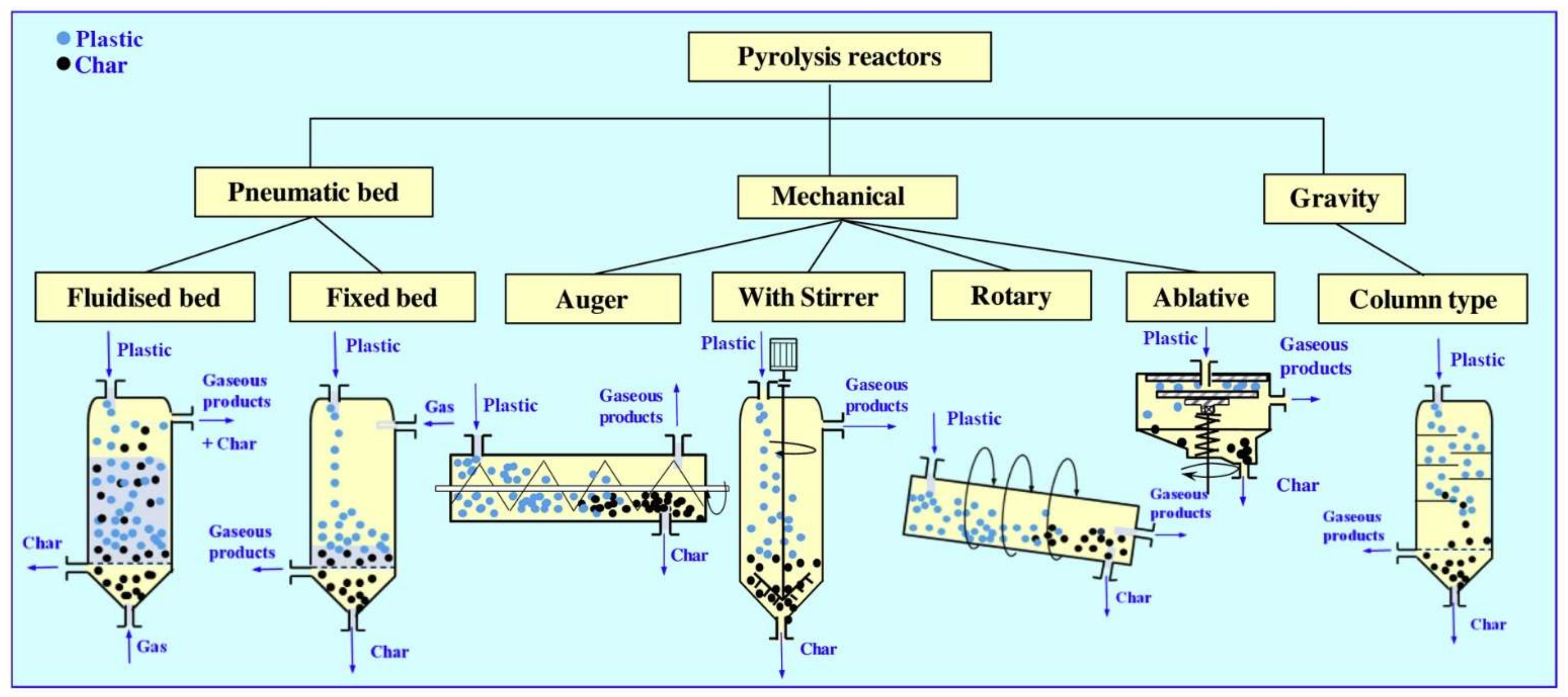
  67. Lewandowski, W.M.; Januszewicz, K.; Kosakowski, W. Efficiency and proportions of waste tyre pyrolysis products depending on the reactor type—A review. J. Anal. Appl. Pyrolysis 2019, 140, 25–53. [Google Scholar] [CrossRef]
  68. Hita, I.; Arabiourrutia, M.; Olazar, M.; Bilbao, J.; Arandes, J.M.; Castaño Sánchez, P. Opportunities and barriers for producing high quality fuels from the pyrolysis of scrap tires. Renew. Sustain. Energy Rev. 2016, 56, 745–759. [Google Scholar] [CrossRef]
  69. Campuzano, F.; Brown, R.C.; Martínez, J.D. Auger reactors for pyrolysis of biomass and wastes. Renew. Sustain. Energy Rev. 2019, 102, 372–409. [Google Scholar] [CrossRef]
  70. Luo, G.; Chandler, D.S.; Anjos, L.C.A.; Eng, R.J.; Jia, P.; Resende, F.L.P. Pyrolysis of whole wood chips and rods in a novel ablative reactor. Fuel 2017, 194, 229–238. [Google Scholar] [CrossRef] [Green Version]
  71. Wu, C.; Williams, P.T. Pyrolysis-gasification of plastics, mixed plastics and real-world plastic waste with and without Ni-Mg-Al catalyst. Fuel 2010, 89, 3022–3032. [Google Scholar] [CrossRef]
  72. Al-asadi, M.; Miskolczi, N. Hydrogen rich products from waste HDPE/LDPE/PP/PET over Me/Ni-ZSM-5 catalysts combined with dolomite. J. Energy Inst. 2021, 96, 251–259. [Google Scholar] [CrossRef]
  73. Miandad, R.; Barakat, M.A.; Rehan, M.; Aburiazaiza, A.S.; Ismail, I.M.I.; Nizami, A.S. Plastic waste to liquid oil through catalytic pyrolysis using natural and synthetic zeolite catalysts. Waste Manag. 2017, 69, 66–78. [Google Scholar] [CrossRef]
  74. Wampler, T.P. Thermometric behavior of polyolefins. J. Anal. Appl. Pyrolysis 1989, 15, 187–195. [Google Scholar] [CrossRef]
  75. Day, M. Influence of temperature and environment on the thermal decomposition of poly(ethylene terephthalate) fibres with and without the flame retardant tris(2,3-dibromopropyl) phosphate. J. Anal. Appl. Pyrolysis 1984, 7, 65–82. [Google Scholar] [CrossRef] [Green Version]
  76. Mastral, F.J.; Esperanza, E.; Garciía, P.; Juste, M. Pyrolysis of high-density polyethylene in a fluidised bed reactor. Influence of the temperature and residence time. J. Anal. Appl. Pyrolysis 2002, 63, 1–15. [Google Scholar] [CrossRef]
  77. Alvarez, J.; Kumagai, S.; Wu, C.; Yoshioka, T.; Bilbao, J.; Olazar, M.; Williams, P.T. Hydrogen production from biomass and plastic mixtures by pyrolysis-gasification. Int. J. Hydrog. Energy 2014, 39, 10883–10891. [Google Scholar] [CrossRef]
  78. Lee, K.H.; Jeon, S.G.; Kim, K.H.; Noh, N.S.; Shin, D.H.; Park, J.; Seo, Y.; Yee, J.J.; Kim, G.T. Thermal and Catalytic Degradation of Waste High-density Polyethylene (HDPE) Using Spent FCC Catalyst. Korean J. Chem. Eng. 2003, 20, 693–697. [Google Scholar] [CrossRef]
  79. Sehested, J. Sintering of nickel steam-reforming catalysts. J. Catal. 2003, 217, 417–426. [Google Scholar] [CrossRef]
  80. Fekhar, B.; Gombor, L.; Miskolczi, N. Pyrolysis of chlorine contaminated municipal plastic waste: In-situ upgrading of pyrolysis oils by Ni/ZSM-5, Ni/SAPO-11, red mud and Ca(OH)2 containing catalysts. J. Energy Inst. 2019, 92, 1270–1283. [Google Scholar] [CrossRef]
  81. Borsodi, N.; Miskolczi, N.; Angyal, A.; Bartha, L. Hydrocarbons obtained by pyrolysis of contaminated waste plastics. In Proceedings of the 45th International Petroleum Conference, Bratislava, Slovakia, 13 June 2011; pp. 1–9. [Google Scholar]
  82. Palmay, P.; Puente, C.; Barzallo, D.; Bruno, J.C. Determination of the Thermodynamic Parameters of the Pyrolysis Process of Post-Consumption Thermoplastics by Non-Isothermal Thermogravimetric Analysis. Polymers 2021, 13, 4379. [Google Scholar] [CrossRef]
  83. Er-rbib, H.; Bouallou, C.; Werkoff, F. Dry reforming of methane—Review of feasibility studies. Chem. Eng. Trans. 2012, 29, 163–168. [Google Scholar] [CrossRef]
  84. Muradov, N.Z.; Veziroǧlu, T.N. From hydrocarbon to hydrogen-carbon to hydrogen economy. Int. J. Hydrog. Energy 2005, 30, 225–237. [Google Scholar] [CrossRef]
  85. Goodman, D.W.; Company, C.; Centre, B.T. Methane Decomposition: Production of Hydrogen and Carbon Filaments. Catalysis 2007, 19, 164–183. [Google Scholar] [CrossRef]
  86. Yao, D.; Wu, C.; Yang, H.; Hu, Q.; Nahil, M.A.; Chen, H.; Williams, P.T. Hydrogen production from catalytic reforming of the aqueous fraction of pyrolysis bio-oil with modified Ni-Al catalysts. Int. J. Hydrog. Energy 2014, 39, 14642–14652. [Google Scholar] [CrossRef] [Green Version]
  87. Aghamohammadi, S.; Haghighi, M.; Maleki, M.; Rahemi, N. Sequential impregnation vs. sol-gel synthesized Ni/Al2O3-CeO2 nanocatalyst for dry reforming of methane: Effect of synthesis method and support promotion. Mol. Catal. 2017, 431, 39–48. [Google Scholar] [CrossRef]
  88. Ren, J.; Cao, J.P.; Zhao, X.Y.; Wei, F.; Zhu, C.; Wei, X.Y. Extension of catalyst lifetime by doping of Ce in Ni-loaded acid-washed Shengli lignite char for biomass catalytic gasification. Catal. Sci. Technol. 2017, 7, 5741–5749. [Google Scholar] [CrossRef]
  89. Xu, J.; Zhou, W.; Li, Z.; Wang, J.; Ma, J. Biogas reforming for hydrogen production over nickel and cobalt bimetallic catalysts. Int. J. Hydrog. Energy 2009, 34, 6646–6654. [Google Scholar] [CrossRef]
  90. Rahemi, N.; Haghighi, M.; Babaluo, A.A.; Jafari, M.F.; Khorram, S. Non-thermal plasma assisted synthesis and physicochemical characterizations of Co and Cu doped Ni/Al2O3 nanocatalysts used for dry reforming of methane. Int. J. Hydrog. Energy 2013, 38, 16048–16061. [Google Scholar] [CrossRef]
  91. Czaplicka, N.; Rogala, A.; Wysocka, I. Metal (Mo, W, Ti) carbide catalysts: Synthesis and application as alternative catalysts for dry reforming of hydrocarbons—A review. Int. J. Mol. Sci. 2021, 22, 2337. [Google Scholar] [CrossRef] [PubMed]
  92. Ma, Y.; Guan, G.; Hao, X.; Cao, J.; Abudula, A. Molybdenum carbide as alternative catalyst for hydrogen production—A review. Renew. Sustain. Energy Rev. 2017, 75, 1101–1129. [Google Scholar] [CrossRef]
  93. Du, X.; France, L.J.; Kuznetsov, V.L.; Xiao, T.; Edwards, P.P.; AlMegren, H.; Bagabas, A. Dry reforming of methane over ZrO2-supported Co–Mo carbide catalyst. Appl. Petrochem. Res. 2014, 4, 137–144. [Google Scholar] [CrossRef] [Green Version]
  94. Takeda, K.; Yamaguchi, A.; Cho, Y.; Anjaneyulu, O.; Fujita, T.; Abe, H.; Miyauchi, M. Metal Carbide as A Light-Harvesting and Anticoking Catalysis Support for Dry Reforming of Methane. Glob. Chall. 2020, 4, 1900067. [Google Scholar] [CrossRef] [Green Version]
  95. Guo, J.; Zhang, A.J.; Zhu, A.M.; Xu, Y.; Au, C.T.; Shi, C. A carbide catalyst effective for the dry reforming of methane at atmospheric pressure. ACS Symp. Ser. 2010, 1056, 181–196. [Google Scholar] [CrossRef]
  96. Brungs, A.J.; York, A.P.E.; Claridge, J.B.; Márquez-Alvarez, C.; Green, M.L.H. Dry reforming of methane to synthesis gas over supported molybdenum carbide catalysts. Catal. Lett. 2000, 70, 117–122. [Google Scholar] [CrossRef]
  97. Zhang, Q.; Pastor-Pérez, L.; Gu, S.; Reina, T.R. Transition metal carbides (TMCS) catalysts for gas phase CO2 upgrading reactions: A comprehensive overview. Catalysts 2020, 10, 955. [Google Scholar] [CrossRef]
  98. Mounfield, W.P.; Harale, A.; Román-Leshkov, Y. Impact of morphological effects on the activity and stability of tungsten carbide catalysts for dry methane reforming. Energy Fuels 2019, 33, 5544–5550. [Google Scholar] [CrossRef]
  99. Zhang, L.; Yang, Y.; Yao, Z.; Yan, S.; Kang, X. Finding of a new cycle route in Ni/Mo2C catalyzed CH4-CO2reforming. Catal. Sci. Technol. 2021, 11, 479–483. [Google Scholar] [CrossRef]
  100. Lalsare, A.D.; Leonard, B.; Robinson, B.; Sivri, A.C.; Vukmanovich, R.; Dumitrescu, C.; Rogers, W.; Hu, J. Self-regenerable carbon nanofiber supported Fe–Mo2C catalyst for CH4-CO2 assisted reforming of biomass to hydrogen rich syngas. Appl. Catal. B Environ. 2021, 282, 119537. [Google Scholar] [CrossRef]
  101. Shao, H.; Kugler, E.L.; Ma, W.; Dadyburjor, D.B. Effect of temperature on structure and performance of in-house cobalt-tungsten carbide catalyst for dry reforming of methane. Ind. Eng. Chem. Res. 2005, 44, 4914–4921. [Google Scholar] [CrossRef]
  102. Zhang, Y.; Zhang, S.; Zhang, X.; Qiu, J.; Yu, L.; Shi, C. Ni modified WC x catalysts for methane dry reforming. In Advances in CO2 Capture, Sequestration, and Conversion; American Chemical Society: Washington, DC, USA, 2015; pp. 171–189. [Google Scholar]
  103. Porosoff, M.D.; Myint, M.N.Z.; Kattel, S.; Xie, Z.; Gomez, E.; Liu, P.; Chen, J.G. Identifying Different Types of Catalysts for CO2 Reduction by Ethane through Dry Reforming and Oxidative Dehydrogenation. Angew. Chem. Int. Ed. 2015, 54, 15501–15505. [Google Scholar] [CrossRef] [PubMed]
  104. Solymosi, F.; Németh, R.; Oszkó, A. The oxidative dehydrogenation of propane with CO2 over supported Mo2C catalyst. Stud. Surf. Sci. Catal. 2001, 136, 339–344. [Google Scholar] [CrossRef]
  105. Ronda-Lloret, M.; Marakatti, V.S.; Sloof, W.G.; Delgado, J.J.; Sepúlveda-Escribano, A.; Ramos-Fernandez, E.V.; Rothenberg, G.; Shiju, N.R. Butane Dry Reforming Catalyzed by Cobalt Oxide Supported on Ti2AlC MAX Phase. ChemSusChem 2020, 13, 6401–6408. [Google Scholar] [CrossRef]
  106. Ochoa, A.; Bilbao, J.; Gayubo, A.G.; Castaño, P. Coke formation and deactivation during catalytic reforming of biomass and waste pyrolysis products: A review. Renew. Sustain. Energy Rev. 2020, 119, 109600. [Google Scholar] [CrossRef]
  107. Ferella, F.; Stoehr, J.; De Michelis, I.; Hornung, A. Zirconia and alumina based catalysts for steam reforming of naphthalene. Fuel 2013, 105, 614–629. [Google Scholar] [CrossRef]
  108. Barbarias, I.; Artetxe, M.; Lopez, G.; Arregi, A.; Santamaria, L.; Bilbao, J.; Olazar, M. Catalyst performance in the HDPE pyrolysis-reforming under reaction-regeneration cycles. Catalysts 2019, 9, 414. [Google Scholar] [CrossRef] [Green Version]
  109. Arandia, A.; Remiro, A.; García, V.; Castaño, P.; Bilbao, J.; Gayubo, A.G. Oxidative steam reforming of raw bio-oil over supported and bulk Ni catalysts for hydrogen production. Catalysts 2018, 8, 322. [Google Scholar] [CrossRef] [Green Version]
  110. Li, D.; Koike, M.; Wang, L.; Nakagawa, Y.; Xu, Y.; Tomishige, K. Regenerability of hydrotalcite-derived nickel-iron alloy nanoparticles for syngas production from biomass tar. ChemSusChem 2014, 7, 510–522. [Google Scholar] [CrossRef] [PubMed]
  111. Li, D.; Nakagawa, Y.; Tomishige, K. Development of Ni-based catalysts for steam reforming of tar derived from biomass pyrolysis. Cuihua Xuebao/Chin. J. Catal. 2012, 33, 583–594. [Google Scholar] [CrossRef]
  112. Wu, C.; Williams, P.T. Effects of gasification temperature and catalyst ratio on hydrogen production from catalytic steam pyrolysis-gasification of polypropylene. Energy Fuels 2008, 22, 4125–4132. [Google Scholar] [CrossRef]
  113. Wu, C.; Williams, P.T. Pyrolysis-gasification of post-consumer municipal solid plastic waste for hydrogen production. Int. J. Hydrog. Energy 2010, 35, 949–957. [Google Scholar] [CrossRef]
  114. Wu, S.L.; Kuo, J.H.; Wey, M.Y. Thermal degradation of waste plastics in a two-stage pyrolysis-catalysis reactor over core-shell type catalyst. J. Anal. Appl. Pyrolysis 2019, 142, 104641. [Google Scholar] [CrossRef]
  115. Wysocka, I.; Mielewczyk-Gryń, A.; Łapiński, M.; Cieślik, B.; Rogala, A. Effect of small quantities of potassium promoter and steam on the catalytic properties of nickel catalysts in dry/combined methane reforming. Int. J. Hydrog. Energy 2021, 46, 3847–3864. [Google Scholar] [CrossRef]
  116. Gangadharan, P.; Kanchi, K.C.; Lou, H.H. Evaluation of the economic and environmental impact of combining dry reforming with steam reforming of methane. Chem. Eng. Res. Des. 2012, 90, 1956–1968. [Google Scholar] [CrossRef]
  117. Di Blasi, C. Combustion and gasification rates of lignocellulosic chars. Prog. Energy Combust. Sci. 2009, 35, 121–140. [Google Scholar] [CrossRef]
  118. York, A.P.E.; Xiao, T.C.; Green, M.L.H.; Claridge, J.B. Methane oxyforming for synthesis gas production. Catal. Rev. Sci. Eng. 2007, 49, 511–560. [Google Scholar] [CrossRef]
  119. Azizi, Z.; Rezaeimanesh, M.; Tohidian, T.; Rahimpour, M.R. Dimethyl ether: A review of technologies and production challenges. Chem. Eng. Process. 2014, 82, 150–172. [Google Scholar] [CrossRef]
  120. Guilhaume, N.; Bianchi, D.; Wandawa, R.A.; Yin, W.; Schuurman, Y. Study of CO2 and H2O adsorption competition in the combined dry/steam reforming of biogas. Catal. Today 2021, 375, 282–289. [Google Scholar] [CrossRef]
  121. Nileshkumar, K.D.; Patel, T.M.; Rathod, G.P. Effect of Blend Ratio of Plastic Pyrolysis Oil and Diesel Fuel on the Performance of Single Cylinder CI Engine. Int. J. Sci. Technol. Eng. 2015, 1, 195–203. [Google Scholar]
  122. Rehan, M.; Nizami, A.S.; Shahzad, K.; Ouda, O.K.M.; Ismail, I.M.I.; Almeelbi, T.; Iqbal, T.; Demirbas, A. Pyrolytic liquid fuel: A source of renewable electricity generation in Makkah. Energy Sources Part A Recover. Util. Environ. Eff. 2016, 38, 2598–2603. [Google Scholar] [CrossRef]
  123. Saptoadi, H.; Pratama, N.N. Utilization of Plastics Waste Oil as Partial Substitute for Kerosene in Pressurized Cookstoves. Int. J. Environ. Sci. Dev. 2015, 6, 363–368. [Google Scholar] [CrossRef] [Green Version]
  124. Miandad, R.; Rehan, M.; Barakat, M.A.; Aburiazaiza, A.S.; Khan, H.; Ismail, I.M.I.; Dhavamani, J.; Gardy, J.; Hassanpour, A.; Nizami, A.S. Catalytic pyrolysis of plastic waste: Moving toward pyrolysis based biorefineries. Front. Energy Res. 2019, 7, 27. [Google Scholar] [CrossRef] [Green Version]
  125. Ravenni, G.; Cafaggi, G.; Sárossy, Z.; Rohde Nielsen, K.T.; Ahrenfeldt, J.; Henriksen, U.B. Waste chars from wood gasification and wastewater sludge pyrolysis compared to commercial activated carbon for the removal of cationic and anionic dyes from aqueous solution. Bioresour. Technol. Rep. 2020, 10, 100421. [Google Scholar] [CrossRef]
  126. Doumer, M.E.; Arízaga, G.G.C.; Da Silva, D.A.; Yamamoto, C.I.; Novotny, E.H.; Santos, J.M.; Dos Santos, L.O.; Wisniewski, A.; De Andrade, J.B.; Mangrich, A.S. Slow pyrolysis of different Brazilian waste biomasses as sources of soil conditioners and energy, and for environmental protection. J. Anal. Appl. Pyrolysis 2015, 113, 434–443. [Google Scholar] [CrossRef]
  127. Suopajärvi, H.; Pongrácz, E.; Fabritius, T. The potential of using biomass-based reducing agents in the blast furnace: A review of thermochemical conversion technologies and assessments related to sustainability. Renew. Sustain. Energy Rev. 2013, 25, 511–528. [Google Scholar] [CrossRef]
  128. Harussani, M.M.; Sapuan, S.M.; Rashid, U.; Khalina, A.; Ilyas, R.A. Pyrolysis of polypropylene plastic waste into carbonaceous char: Priority of plastic waste management amidst COVID-19 pandemic. Sci. Total Environ. 2022, 803, 149911. [Google Scholar] [CrossRef]
  129. Garg, K.K.; Pandey, S.; Kumar, A.; Rana, A.; Sahoo, N.G.; Singh, R.K. Graphene nanosheets derived from waste plastic for cost-effective thermoelectric applications. Results Mater. 2022, 13, 100260. [Google Scholar] [CrossRef]
  130. Sogancioglu, M.; Yel, E.; Ahmetli, G. Behaviour of waste polypropylene pyrolysis char-based epoxy composite materials. Environ. Sci. Pollut. Res. 2020, 27, 3871–3884. [Google Scholar] [CrossRef] [PubMed]
Figure 1. Types of pyrolysis and the impact of process parameters on product distribution.
Catalysts 12 00362 g001
Figure 2. Different reactor configurations used in the laboratory scale pyrolysis-catalytic dry reforming process: (a) Two-stage reactor; (b) Two-stage reactor system consisting of two separate reactors; (c) One-stage reactor.
Catalysts 12 00362 g002
Figure 3. Different types of pyrolysis reactors. Reproduced with copyright permission from [67] (Elsevier).
Catalysts 12 00362 g003
Table 1. Typical technological parameters of different types of pyrolysis [23].
Pyrolysis TypeProcess DurationTemperature [K]Heating Rate [K/min]
Conventional/slow10 min–10 h500–9005–10
Fast10–20 min700–90050–100
Flash/ultra-fast<10 min1000–1300>100
Table 2. Selected process parameters of the pyrolysis of plastics and obtained product distribution.
Plastic FeedstockPyrolysis TypeTemperature [K]Heating Rate CatalystCat.:Plastic Mass RatioProduct DistributionRef.
[wt %]
[K/min]GasOilChar
Mixed plastic waste 1Slow77310--14.275.810.0[36]
Mixed plastic waste 1Slow77320--10.582.08.5[36]
Mixed plastic waste 1Flash773Isothermal--91.07.02.0[36]
ABSFast773Isothermal--5.291.03.8[34]
PVCFast773Isothermal--44.335.919.8[34]
PEFlash1273Isothermal-->99n.d.n.d.[35]
PPFlash873Isothermal--61390[43]
PEFlash873Isothermal--67330[43]
PSFlash873Isothermal--65350[43]
PETFlash873Isothermal--484012[43]
PSSlow10735--2.2895.771.95[44]
PSSlow107310--3.4095.791.81[44]
PSSlow107315--5.6592.751.60[44]
PSSlow107320--6.3192.651.04[44]
PESlow10735--18.1781.650.18[44]
PESlow107310--18.5781.330.10[44]
PESlow107315--27.3672.630.01[44]
PESlow107320--38.7661.240.00[44]
ABSSlow10735--2.8995.991.12[44]
ABSSlow107310--5.9192.661.43[44]
ABSSlow107315--8.0690.471.47[44]
ABSSlow107320--8.8689.571.57[44]
PETSlow10735--51.6139.029.37[44]
PETSlow107310--56.3235.408.28[44]
PETSlow107315--64.5429.715.75[44]
PETSlow107320--65.2129.165.63[44]
PPSlow10735--16.5583.340.11[44]
PPSlow107310--17.2082.670.13[44]
PPSlow107315--17.8882.020.10[44]
PPSlow107320--31.8468.060.10[44]
PESlow77310--n.d.95%n.d.[42]
PESlow773; TC = 67310ZSM-5n.d.58411[42]
PESlow773; TC = 72310ZSM-5n.d.10828[42]
PESlow773; TC = 77310ZSM-5n.d.18766[42]
PESlow773; TC = 82310ZSM-5n.d.22735[42]
PESlow773; TC = 87310ZSM-5n.d.28675[42]
PESlow773; TC = 67310Y -zeoliten.d.58411[42]
PESlow773; TC = 72310Y -zeoliten.d.107911[42]
PESlow773; TC = 77310Y -zeoliten.d.117712[42]
PESlow773; TC = 82310Y -zeoliten.d.117613[42]
PESlow773; TC = 87310Y -zeoliten.d.197011[42]
PETFast723Isothermal--205921[38]
PETFast873Isothermal--196714[38]
PETFast723IsothermalZSM-52:1552124[38]
PETFast723IsothermalZSM-54:1631225[38]
PETFast723IsothermalZSM-56:169922[38]
PETFast873IsothermalZSM-52:1512920[38]
PETFast873IsothermalZSM-54:1602614[38]
PETFast873IsothermalZSM-56:1661410[38]
PETFast723IsothermalNiCl21:227658[38]
PETFast723IsothermalNiCl21:118775[38]
PETFast873IsothermalNiCl21:242553[38]
PETFast873IsothermalNiCl21:129692[38]
HDPESlow97325--18.079.70.0[45]
LDPESlow97325--15.184.30.0[45]
PPSlow97325--15.384.40.2[45]
PSSlow97325--3.483.83.5[45]
PVCSlow97325--2.584.6213.8[45]
PETSlow97325--38.741.315.6[45]
LDPESlow7736--9.190.90.0[28]
LDPEFast77360--13.786.20.0[28]
LDPESlow6731--16.8882.680.44[27]
HDPESlow6731--16.7882.660.56[27]
PPSlow6731--16.5383.160.31[27]
LDPE, HDPE, PP mixture 2Slow6731--17.0482.250.71[27]
Packaging plastic waste 3Slow6731--21.3674.983.66[27]
HDPESlow7735--7930[46]
PPSlow7735--5950[46]
PSSlow7735--27127[46]
PETSlow7735--321553[46]
HDPEFlash923Isothermal--21.178.90.0[47]
HDPEFlash1003Isothermal--79.320.70.0[47]
HDPEFlash1123Isothermal--83.816.20.0[47]
1 Mixture consisted of 58.6% PE, 26.9% PP, 5.6% PET, 8.8% PS, 0.1% thermosets. 2 Mixture of equal quantities of each plastic. 3 Mixture of equal quantities of waste LDPE, HDPE, and PP. n.d.—no data. Tc—temperature of the catalyst bed.
Table 3. PCDR processes reported in the literature with different process parameters and the yield and H2/CO ratio of obtained syngas.
FeedstockReactor ConfigurationOperating ConditionsCatalystCat.:Plastic Mass RatioProduct YieldH2/CO Molar RatioRef.
PETwo-stage fixed bed reactor systemTPyr = 720 KPd/Al2O311.2YH2 = 35.4%n.d.[9]
TDR = 910 KYCO = 24.5% 1
LDPETwo-stage fixed bed reactor systemTPyr = 773 KNi–Co–Al0.5Ysyngas = 154.7 mmol g−1plastic0.6[10]
HDPEYsyngas = 149.4 mmol g−1plastic0.5
PPYsyngas = 136.0 mmol g−1plastic0.5
PSTDR = 1073 KYsyngas = 126.3 mmol g−1plastic0.3
PETYsyngas = 63.0 mmol g−1plastic0.2
SWP 2Ysyngas = 148.6 mmol g−1plastic0.5
SWP 2Two-stage fixed bed reactor systemTPyr = 773 KNi–Co–Al2O30.5Ysyngas = 116.2 mmol g−1plastic0.55[13]
TDR = 873 K
TPyr = 773 KYsyngas = 144.0 mmol g−1plastic0.48
TDR = 973 K
TPyr = 773 KYsyngas = 148.6 mmol g−1plastic0.49
TDR = 1073 K
TPyr = 773 KYsyngas = 125.8 mmol g−1plastic0.66
TDR = 1173 K
SWP 2Two-stage fixed bed reactor systemTPyr = 773 KNi–Co–Al2O30.25Ysyngas = 141.3 mmol g−1plastic0.48[13]
0.5Ysyngas = 148.6 mmol g−1plastic0.49
TDR = 1073 K1Ysyngas = 143.9 mmol g−1plastic0.49
1.5Ysyngas = 139.9 mmol g−1plastic0.51
SWP 2Two-stage fixed bed reactor systemTPyr = 773 KNi–Co/Al2O30.5Ysyngas = 96 mmol g−1plastic0.72[15]
TDR = 1073 K
Steam addition:
CO2:steam = 4:0
TPyr = 773 KYsyngas = 107 mmol g−1plastic0.88
TDR = 1073 K
Steam addition:
CO2:steam = 4:0.5
TPyr = 773 KYsyngas = 136 mmol g−1plastic0.93
TDR = 1073 K
Steam addition:
CO2:steam = 4:1
TPyr = 773 KYsyngas = 159 mmol g−1plastic0.85
TDR = 1073 K
Steam addition:
CO2:steam = 4:1.5
TPyr = 773 KYsyngas = 156 mmol g−1plastic0.83
TDR = 1073 K
Steam addition:
CO2:steam = 4:2
SWP 2Two-stage fixed bed reactor systemTPyr = 773 KNi–Mg/Al2O30.5Ysyngas = 108 mmol g−1plastic0.69[15]
TDR = 1073 K
Steam addition:
CO2:steam = 4:0
TPyr = 773 KYsyngas = 113 mmol g−1plastic0.60
TDR = 1073 K
Steam addition:
CO2:steam = 4:0.5
TPyr = 773 KYsyngas = 147mmol g−1plastic0.75
TDR = 1073 K
Steam addition:
CO2:steam = 4:1
TPyr = 773 KYsyngas = 144 mmol g−1plastic1.09
TDR = 1073 K
Steam addition:
CO2:steam = 4:2
TPyr = 773 KYsyngas = 132 mmol g−1plastic1.41
TDR = 1073 K
Steam addition:
CO2:steam = 4:3
HDPETwo-stage fixed bed reactor systemTPyr = 773 KNi–Mg/Al2O30.5Ysyngas = 132 mmol g−1plastic0.5[66]
TDR = 1073 K
HDPETwo-stage fixed bed reactor systemTPyr = 773 KNi-Al0.5Ysyngas = 138.81 mmol g−1plastic0.47[65]
Ni–Cu–AlYsyngas = 130.56 mmol g−1plastic0.51
TDR = 1073 KNi–Mg–AlYsyngas = 146.96 mmol g−1plastic0.49
Ni–Co–AlYsyngas = 149.42 mmol g−1plastic0.47
PPTwo-stage fixed bed reactor systemTPyr = 773 KNi/Al2O30.5Ysyngas = 170 mmol g−1plastic0.41[12]
TDR = 1073 KRu–Ni/Al2O3Ysyngas = 160 mmol g−1plastic0.35
Mixture of real waste plastics 3One-stage horizontal tubular reactorT = 823 KNi/ZSM-50.5Ysyngas = 60.2 mmol g−1plastic1.80[17]
Ca/Ni/ZSM-5Ysyngas = 58.0 mmol g−1plastic2.03
Ce/Ni/ZSM-5Ysyngas = 61.1 mmol g−1plastic1.83
La/Ni/ZSM-5Ysyngas = 53.7 mmol g−1plastic2.23
Mg/Ni/ZSM-5Ysyngas = 51.9 mmol g−1plastic2.18
Mn/Ni/ZSM-5Ysyngas = 57.4 mmol g−1plastic2.12
Mixture of real waste plastics 3One-stage horizontal tubular reactorT = 1123 KNi/ZSM-50.5Ysyngas = 112.6 mmol g−1plastic1.81[17]
Ca/Ni/ZSM-5Ysyngas = 112.2 mmol g−1plastic2.03
Ce/Ni/ZSM-5Ysyngas = 132.0 mmol g−1plastic1.89
La/Ni/ZSM-5Ysyngas = 119.2 mmol g−1plastic2.23
Mg/Ni/ZSM-5Ysyngas = 103.8 mmol g−1plastic2.19
Mn/Ni/ZSM-5Ysyngas = 100.3 mmol g−1plastic2.09
Mixture of real waste plastics 3One-stage horizontal tubular reactorT = 823 K;Ni/ZSM-50.5Ysyngas = 12.7 mmol g−1plastic1.70[72]
Ca/Ni/ZSM-5Ysyngas = 11.7 mmol g−1plastic1.93
Ce/Ni/ZSM-5Ysyngas = 15.1 mmol g−1plastic2.08
In situ CO2 generation using dolomiteLa/Ni/ZSM-5Ysyngas = 13.8 mmol g−1plastic2.07
Mg/Ni/ZSM-5Ysyngas = 10.5 mmol g−1plastic2.00
Mn/Ni/ZSM-5Ysyngas = 9.8 mmol g−1plastic1.80
Mixture of real waste plastics 3One-stage horizontal tubular reactorT = 1123 K;Ni/ZSM-50.5Ysyngas = 95.2 mmol g−1plastic1.83[72]
Ca/Ni/ZSM-5Ysyngas = 96.3 mmol g−1plastic2.01
Ce/Ni/ZSM-5Ysyngas = 115.6 mmol g−1plastic1.78
In situ CO2 generation using dolomiteLa/Ni/ZSM-5Ysyngas = 111.8 mmol g−1plastic2.11
Mg/Ni/ZSM-5Ysyngas = 90.8 mmol g−1plastic1.99
Mn/Ni/ZSM-5Ysyngas = 106.3 mmol g−1plastic1.98
Mixed plastics from household packaging 4Two-stage fixed bed reactor systemTPyr = 773 KNi/Al2O30.5Ysyngas = 146.32 mmol g−1plastic0.46[14]
TDR = 1073 KNi–Co/Al2O3Ysyngas = 156.45 mmol g−1plastic0.48
Mixed plastics from building construction 5Two-stage fixed bed reactor systemTPyr = 773 KNi/Al2O30.5Ysyngas = 143.85 mmol g−1plastic0.50
TDR = 1073 KNi–Co/Al2O3Ysyngas = 141.47 mmol g−1plastic0.47
Mixed plastics from agriculture 6Two-stage fixed bed reactor systemTPyr = 773 KNi/Al2O30.5Ysyngas = 153.67 mmol g−1plastic0.48
TDR = 1073 KNi–Co/Al2O3Ysyngas = 121.26 mmol g−1plastic0.54
Mixed plastics from freezer and refrigerator
equipment
Two-stage fixed bed reactor systemTPyr = 773 KNi/Al2O30.5Ysyngas = 72.51 mmol g−1plastic0.46
TDR = 1073 KNi–Co/Al2O3Ysyngas = 72.12 mmol g−1plastic0.42
Mixed plastic from cathode ray tubeTwo-stage fixed bed reactor systemTPyr = 773 KNi/Al2O30.5Ysyngas = 79.84 mmol g−1plastic0.50
TDR = 1073 KNi–Co/Al2O3Ysyngas = 92.63 mmol g−1plastic0.46
Mixed plastics from electrical and electronic equipmentTwo-stage fixed bed reactor systemTPyr = 773 KNi/Al2O30.5Ysyngas = 85.49 mmol g−1plastic0.34
TDR = 1073 KNi–Co/Al2O3Ysyngas = 87.26 mmol g−1plastic0.37
Refuse-derived fuelTwo-stage fixed bed reactor systemTPyr = 773 KNi/Al2O30.5Ysyngas = 41.24 mmol g−1plastic0.32
TDR = 1073 KNi–Co/Al2O3Ysyngas = 41.49 mmol g−1plastic0.34
SWP 2Two-stage fixed bed reactor systemTPyr = 773 KNi/Al2O30.5Ysyngas = 140.53 mmol g−1plastic0.48
TDR = 1073 KNi–Co/Al2O3Ysyngas = 148.56 mmol g−1plastic0.50
1 PE was completely reformed to CO and H2 when the catalyst temperature was increased to 1120 K. 2 The simulated waste plastic (SWP) mixture consisted of 42 wt % LDPE, 20 wt % HDPE, 16 wt % PS, 12 wt % PET, and 10 wt % PP. 3 Mixture from municipal sources consisted of LDPE (14 wt %), HDPE (17 wt %), PP (19 %), PET (45 wt %) and other polymers (5 wt %). 4 Mixture mainly consisted of HDPE and PET. 5 Mixture mainly consisted of PS, PU, PE and PP. 6 Mixture mainly consisted of HDPE, LDPE and PP. n.d.—no data; TPyr—temperature of pyrolysis; TDR—temperature of dry reforming.
Table 4. Synthesis gas end-use applications depending on the H2/CO ratio [52,60,118,119].
H2/CO Molar RatioEnd-Use Application
1Formaldehyde, polycarbonates, iron ore reduction, dimethyl ether
2Methanol, Fisher–Tropsch syntheses
3 or greaterNH3, H2
Publisher’s Note: MDPI stays neutral with regard to jurisdictional claims in published maps and institutional affiliations.

