Article

Clarification of Catalytic Effect on Large Stretchable and Compressible Rubber Dye-Sensitized Solar Cells

1
Faculty of Symbiotic Systems Sciences, Fukushima University, 1 Kanayagawa, Fukushima 960-1296, Japan
2
Institute of Innovative Research, Tokyo Institute of Technology, 2-12-1 Ookayama, Meguro-ku, Tokyo 152-8550, Japan
*
Author to whom correspondence should be addressed.
Energies 2020, 13(24), 6658; https://doi.org/10.3390/en13246658
Submission received: 9 November 2020 / Revised: 7 December 2020 / Accepted: 14 December 2020 / Published: 17 December 2020

Abstract

:
Rubber involving magnetic compound fluid (MCF) and TiO2 is effective in dye-sensitized solar cells (DSSCs) to create large efficacy. Wearable and portable solar cells made of MCF rubber are the most desirable as soft materials in robots or flexible devices, and they are further desirable because they have self-generated power and power supply with sensing. Therefore, we investigated the effect of TiO2 catalysts on the photovoltaic effect of MCF rubber DSSCs under large tension and compression. The characteristics of the built-in electricity and photoelectricity were clarified experimentally. The experimental results were explained by a chemical–photovoltaic mechanism involving the behavior of dye, electrolytes, water, and rubber molecules, as well as a catalytic effect of the metal component of the MCF on Ni, Fe3O4, and TiO2. Once we are able to produce solar cells that have large tension and compression, the present experimental results and the model of the chemical–photovoltaic mechanism will be of great interest.

1. Introduction

The problem of global energy consumption is being addressed in order to resolve the continuously ascending consumption of energy that boosts global warming and acid rain. Therefore, solar cells are receiving remarkable attention as a renewable energy technology. Organic solar cells have become expectable, including various types structured with organic or inorganic materials [1,2,3] or with organic or inorganic materials including liquids [4] such as ionic liquid [5,6,7,8,9,10] and dielectric liquid [11]. Above all, dye-sensitized solar cells (DSSCs) [12,13] such as Gratzel-type solar cells [14] and Perovskite-type solar cells [15] are well known to be lightweight low-cost cells. These organic solar cells are viable materials in the creation of flexible engineering instruments that lead to wearable and portable electronic devices, as opposed to rigid-type solar cells made of solid semiconductors such as silicon and metal glass. The wearable and portable devices may include self-powered supply or health monitors [16] and electronic devices embedded in clothes, watches, or glasses [17]. In order to achieve flexibility, not only polymers [18,19,20,21,22] but also thin films [23,24] have been commonly utilized, and fibers [25,26], cloth, or textiles [27] through which electrolytes or dye may be percolated have been proposed. The utilization of rubber is another effective method. However, there have been few studies on the use of rubber, and investigations of silicone rubber (Q) sheets are rare [28,29]. Q in solar cells has been utilized as a substrate of layered materials for photovoltaics, in which case it is not metamorphosed to bring about the photovoltaics [28]. Neither the effects of tension and compression on photovoltaic properties nor experimental data on their correlation have been elucidated [29], due in large part to the lack of clarity regarding the chemical–photovoltaic mechanism and the lack of a high-efficiency profile. In contrast, Shimada proposed suitable solar cells made of rubber involving DSSCs and addressed the cardinal chemical–photovoltaic mechanism [30,31,32,33]. By applying a magnetic compound fluid (MCF), which is a magnetic-responsive fluid compounded with 10 nm sphere magnetite (Fe3O4) particles coated with oleic acid and 1 μm metal particles such as Ni or Fe to the rubber, and with electrolytic polymerization under the application of a magnetic field, the MCF rubber is solidified, producing many needle-like magnetic clusters that are aligned along the magnetic field lines, which have the same direction as the electric field [34,35,36,37,38,39]. The magnetic clusters efficiently induce an exchange of ions and electrons between the Fe3O4 metal particles and rubber molecules because they have a bulk hetero-type structure inside the rubber. Although DSSCs have dye and electrolytes, even if the MCF rubber does not involve dye and electrolytes, the photovoltaic effect can be created. The rubber must be water-soluble rubber with C=C bonds in order for electrolytic polymerization. Therefore, natural rubber (NR) and chloroprene rubber (CR), which are categorized as diene rubber involving C=C bonds, are optimal. If the rubber is non-diene rubber or a water-insoluble rubber such as Q, the MCF rubber needs to include polyvinyl alcohol (PVA) and a water-soluble rubber such as NR or CR [40,41,42]. For example, if we use Q, which is structured as the basis of dimethylpolysiloxane (PDMS), PVA combines PDMS and isoprene molecules of NR or CR via emulsion polymerization so that the non-diene rubber or water-insoluble rubber can be electrolytically polymerized. The photovoltaic effect is created because Fe3O4 metal particles, rubber, and water molecules have p-type and n-type semiconductor-like roles in the form of ionized A (A is the acceptor) and D+ (D is the donor) [30,31]. Naturally, when the MCF rubber involves dye and electrolytes to be electrolytically polymerized, the photovoltaic effect can also manifest as materialized DSSCs. The MCF rubber not only has a photovoltaic effect, but also has sensing capabilities [30,31,32,33] and serves as a capacitor [32]. In addition, the brilliant peculiarity of MCF rubber is that it is largely stretchable and compressible [31]. Regarding previous studies on flexible solar cells utilizing polymers or thin films, the solar cells bend but do not stretch and are, therefore, considered solid films [23,24]. Alternatively, the deformation of the solar cells is so small that the tensile and compressive rates are not comparatively very large. However, MCF rubber can be stretched to twice its original length or compressed to half its initial size. Therefore, wearable and portable solar cells made of MCF rubber are highly promising for use as soft materials in robots and flexible devices, especially because of their self-generated power and power supply with sensing.
As a general technique that has been seen in the case of ordinary solar cells, involving a catalyst is an effective way of enhancing the high efficiency of solar cells. In water-soluble solar cells such as DSSCs, a number of different effective catalysts have been proposed, such as graphite, carbon black, SnO2 [43], Pt [44], MoSx [45], MnWO4, ZnWO4, and CuWO4 [46]. TiO2 is one of many useful catalysts and is effective enough to enhance the photovoltaic effect. Because of the relevant reaction of water on photovoltaics, the chemical–photovoltaic mechanism can be explained by the Honda–Fujishima effect [47]. MCF rubber involving TiO2 is effective in the type of DSSCs that contain MCF in order to achieve large efficacy. However, the effect of TiO2 on DSSCs with MCF remains to be clarified, and the chemical–photovoltaic mechanism involving the catalytic effect has not been dealt with.
In the present study, we investigated the effect of TiO2 as a catalyst on the photovoltaic effect of MCF rubber DSSCs under tension and compression. The experimental results were investigated by using a chemical–photovoltaic mechanism that induces the Honda–Fujishima effect.

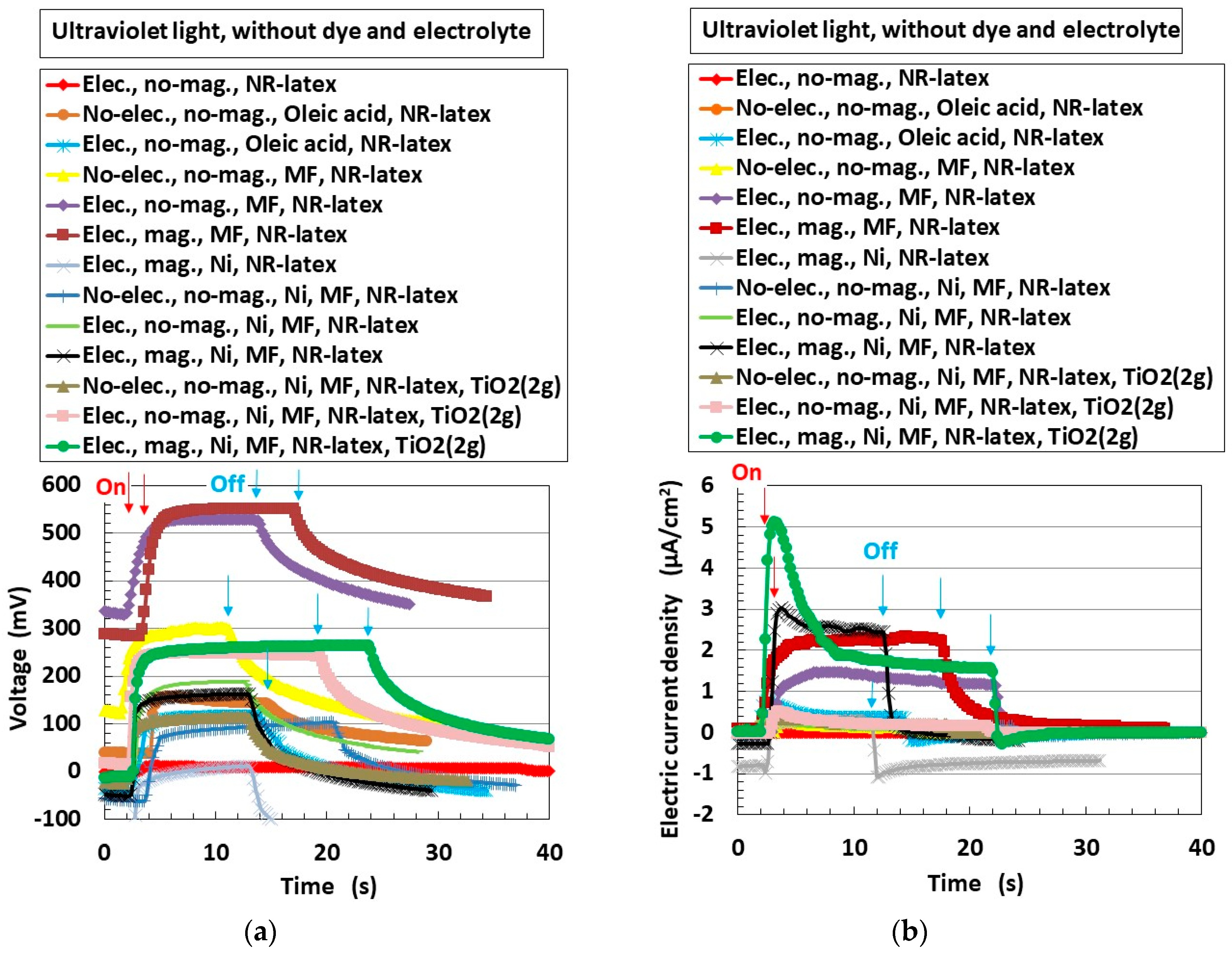
2. Effect of TiO2 on Photovoltaics

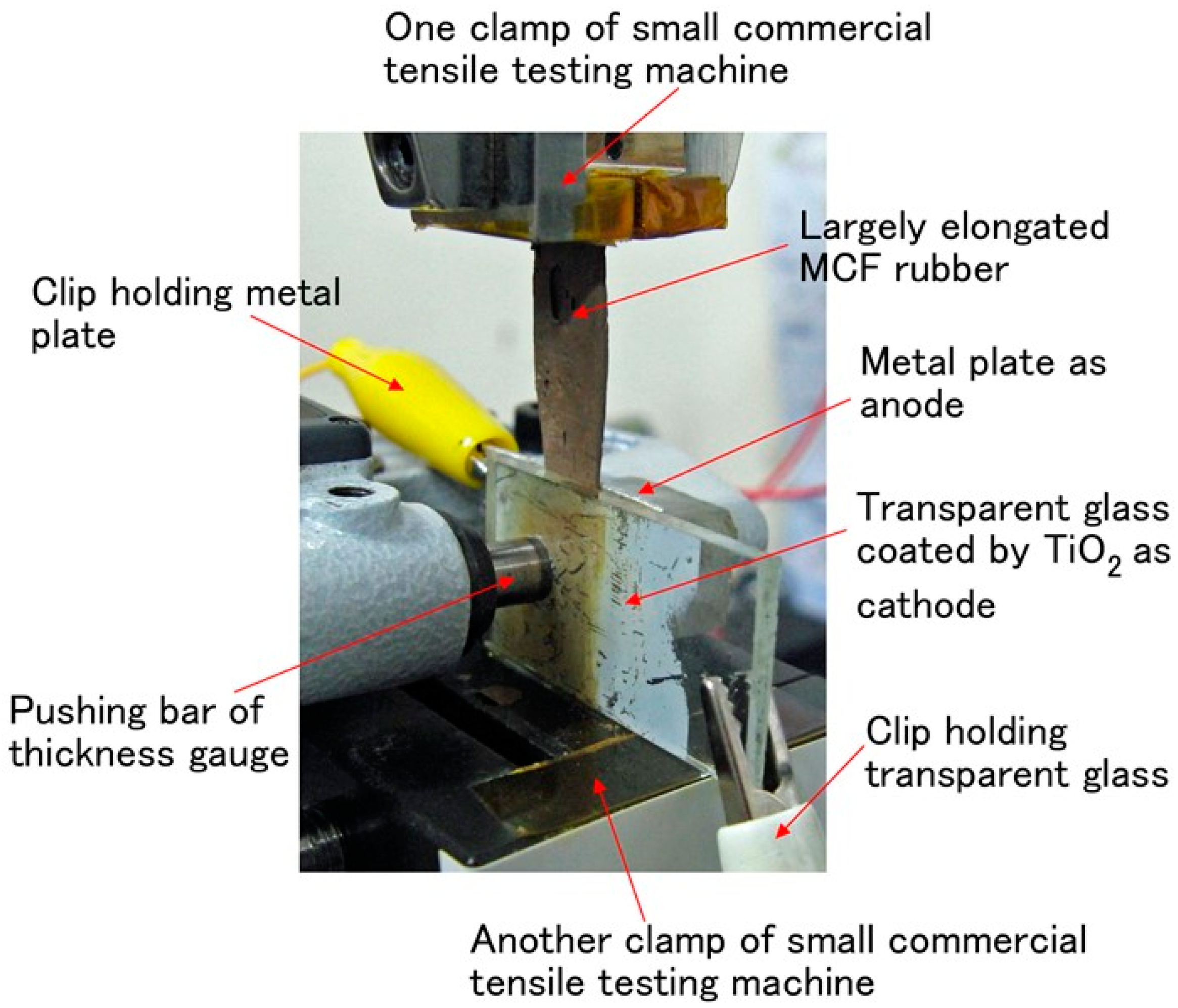
2.1. Experimental Procedure

The experimental procedure of fabricating the MCF rubber DSSCs is shown in Figure A1 in Appendix A. As the first step, we fabricated the MCF rubber. The MCF rubber included the n-type semiconductor TiO2 (titanium with a 10–50 nm particle size, anatase form, Fujifilm Wako Pure Chemical Co., Ltd., Osaka, Japan), 6 g of carbonyl Ni powder with µm ordered and pimple-shaped particles (No. 123, Yamaishi Co., Ltd., Noda, Japan), 4.5 g of water-based magnetic fluid (MF) with 40 wt.% Fe3O4 (W-40 with 10 nm ordered sphere particles, Ichinen Chemicals Co., Ltd., Shibaura, Japan), and 9 g of NR latex (Rejitex Co., Ltd., Atsugi, Japan), mixed using a supersonic stirrer (UR-20P, Tomy Seiko Co., Ltd., Tokyo, Japan) for 5 min and with air evacuated for 15 min. During electrolytic polymerization, an electric field with constant 6 V and 2.7 A was applied between stainless-steel plates with a 1 mm gap for 10 min under atmospheric conditions under the application of a constant 188 mT magnetic field created by neodymium permanent magnets between the electrodes. Therefore, the directions of the electric and magnetic fields were the same. The electrolytically polymerized MCF rubbers had an area of almost 20 mm × 23 mm and a thickness of 1 mm. Next, we constructed the MCF rubber DSSCs. First, 0.17 g of electrolytes and 0.06 g of liquid dye were poured onto the surface of the MCF rubber. The electrolytes took the form of a KI + I2 solution, a mixture of potassium iodide (KI) and iodine (I2) (both from Fujifilm Wako). KI contains 3.3 g of iodine I2 in a solution of 40 g of potassium iodide KI and 60 g of water. The dye is based on ruthenium complexes PEC-TOM-P04 (Peccell Technologies Co., Ltd., Yokohama, Japan). The use of ruthenium dye is ordinary in DSSCs [48]. As shown in Figure A1 (Appendix A), the electrolyte solution was deposited on one side of the MCF rubber at the cathode during electrolytic polymerization (a in Figure A1, Appendix A), and the dye on the other side was deposited at the anode (b in Figure A1, Appendix A). The surface of side a in Figure A1 (Appendix A) was in contact with a transparent glass to serve as an anode of the solar cells, and the surface of side b in Figure A1 (Appendix A) was in contact with a transparent glass coated with TiO2 as a cathode of the solar cell; the MCF rubber was sandwiched between the transparent glasses (20 mm × 30 mm), as shown in Figure 1. The transparent electrode coated with TiO2 was illuminated by visible light (238 Lux) or ultraviolet light (227 Lux). The voltage, electric current, and electrical resistance between the electrodes were measured using a digital multimeter (PC710, Sanwa Supply Co., Ltd., Okayama, Japan).
The surface of the electrolytically polymerized MCF rubber is shown in Figure 2. The cathode side (Figure 2b,d) is typical and shows that the more TiO2 the MCF rubber has, the harder it is to compound TiO2. The compounded condition of TiO2 affects the photovoltaics, as shown in the later figures in the next section.
The MCF rubber involving TiO2 has larger stretchability than commercial pressure-sensitive electrically conductive rubber (PSECR), as shown in our previous study [31]. DSSCs made of MCF rubber involving TiO2 are the most desirable as soft materials in robots or flexible devices, enough to be wearable and portable.

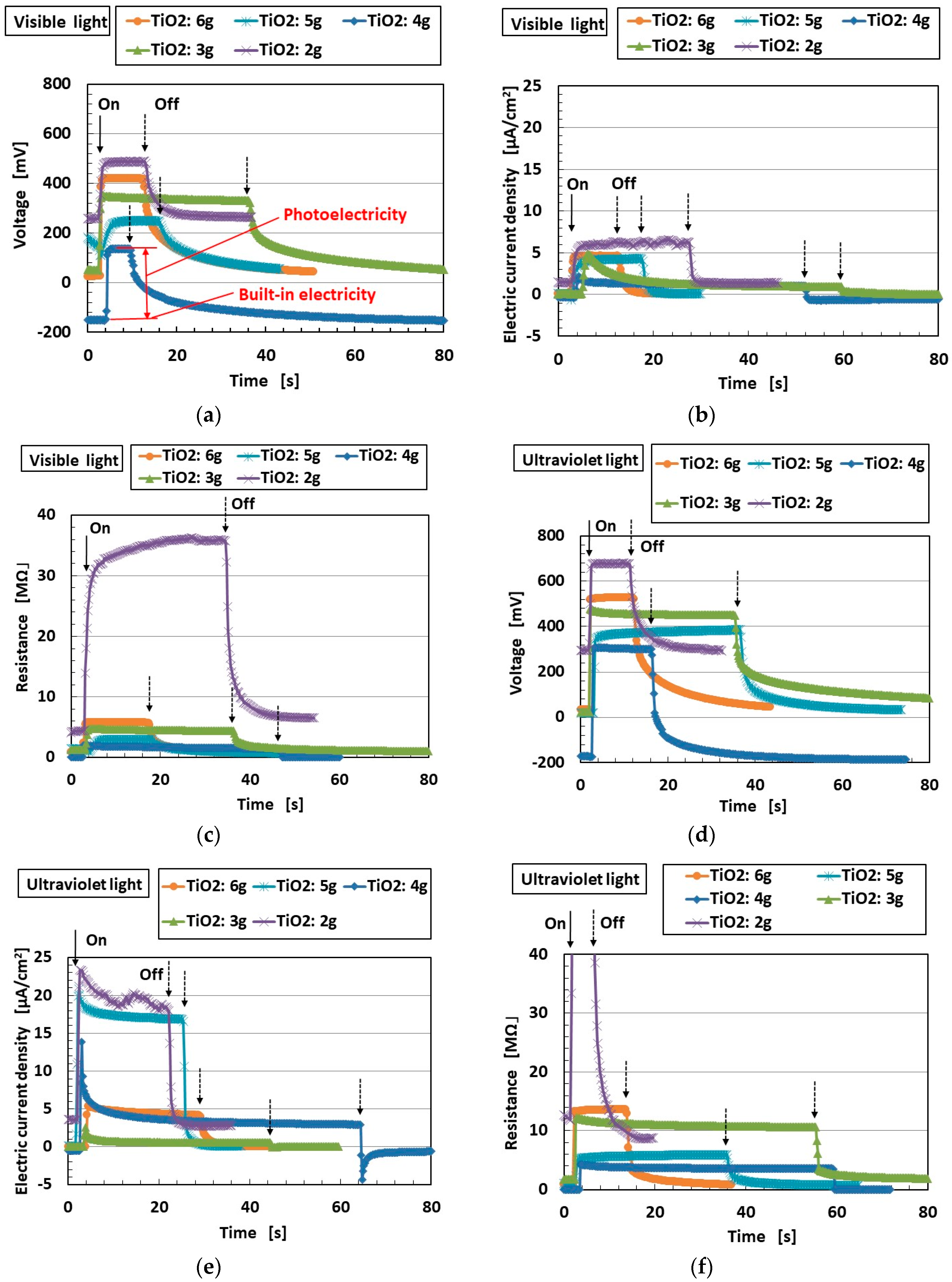
2.2. Experimental Photovolatics

Figure 3 shows the voltage, electric current, and electrical resistance as a function of the amount of TiO2. In the images, “on” with a solid arrow indicates the onset of illumination and “off” with a dotted arrow indicates the termination of illumination. Voltage, electric current, and electrical resistance were measured separately. However, the tendencies of their correlation were obtained and were found to be larger with ultraviolet light than with visible light; that is, MCF rubber DSSCs reacted largely to ultraviolet light.
Under illumination, the electrical resistance increased at the same time that the voltage and electric current increased as a photovoltaic effect. When the illumination was turned off, the electrical resistance decreased at the same time that the voltage and electric current decreased. The electrical resistance under illumination is relevant to microscopic behavior; extraneous electrons cannot be transferred among ionized particles and molecules. Therefore, when photoelectricity was enhanced by illumination, the electrical resistance increased. This behavior is further discussed below.
In some cases, when the sample was first illuminated and the illumination was then turned off, it can be seen that the electric current changed rapidly and then returned smoothly to constant values; this occurred, for example, with the 3 g TiO2 sample under visible light and the 4 g TiO2 sample under ultraviolet light. This was due to dark current or leak current of the solar cells. The incidence of this phenomenon is subject to the varied conditions of the surface of the transparent glass and the MCF rubber during the fabrication of the solar cells, the ambience during fabrication, etc. Furthermore, it is impossible to predict the incidence; thus, certain precautionary measures must be considered. However, since this problem is often seen in ordinary solar cells, the same preemptive methods might be carried out.
Incidentally, the surface of MCF rubber is dark brown, as shown in Figure 1, so that it can absorb light more effectively.
Figure 4 shows the relationship between the electric current I and voltage V measured using a potentiostat (HA-151B, Hokuto Denko Co., Ltd., Tokyo, Japan) at 50 mHz scan rates in the potential domain of −1.5 to 1.5 V. As TiO2 increased, the area surrounded by I and V decreases, and I in particular became larger at the largest V. This means that the MCF rubber solar cell was close to the IV curve of a photodiode [49,50]. On the other hand, our previous study [32] clarified the characteristics of the photodiode under greater tension or compression. MCF rubber solar cells can typically be used as photodiodes. In order to make the characteristics of MCF rubber solar cells more similar to those of photodiodes, more TiO2 might be used, as shown in Figure 4.
The area of the I–V curve connotes the excited-charge regeneration. We can guess the effect of TiO2 on the rate of excited-charge regeneration in the MCF rubber DSSCs. The capacity of the excited-charge regeneration might have an optimal amount of TiO2.
Regarding the general aspects of ordinary photodiodes and solar cells, photodiodes have a longer response time to light scattering than solar cells. In addition, photodiodes might involve dark current. Therefore, dark current also occurs in MCF rubber, as indicated for the 3 g TiO2 in Figure 3b and the 2–5 g TiO2 in Figure 3e.
As shown in Figure 5, focusing on the correlation among the particles of Fe3O4, Ni, and TiO2, and the molecules of rubber, water, and a mixture of potassium iodide (KI) and iodine (I2) electrons were transferred so that the particles and molecules were ionized, corresponding to A and D+ [30,31]. The electrons and holes induced by the transfer of the electrons were mobile such that photoelectricity (photocurrent and photovoltage) was generated by a short circuit created by the photocurrent induced by the transfer of the electrons and holes and the photovoltage induced between the electrons and holes [30,31,34]. On the other hand, the ionized particles and molecules were static and without a mobile state, with the result that the built-in electricity (built-in voltage and built-in current) was created; the voltage between them induced the built-in voltage, while the apparent moving distance between them induced the built-in current. Therefore, MCF rubber also exhibited sensing as a piezo element whose excitement was generated by the built-in voltage reacting to pressure, such that it was a hybrid with both sensor material and solar cell material [31].
The built-in electricity is relevant to the electrical resistance inasmuch as extraneous electrons cannot transfer among ionized particles and molecules via the application of voltage from an outer power supply. In general, in the case of the application of extraneous voltage, electricity as voltage and electric current is categorized in the field of piezo-resistivity, as is built-in electricity. We investigated the relationships among photoelectricity, built-in electricity, and piezo-resistivity in order to clarify the relationship between sensor and solar cells in MCF rubber. Figure 6a shows the changes in electrical resistance by pressure, which corresponds to piezo-resistivity. The state at the initial zero pressure corresponds to built-in electricity. As pressure increases, the electrical resistance decreases because electrons transfer easily between the ionized particles and molecules by decreasing the distance between them. Under the greatest pressure, the electrical resistance is saturated and constant because the distance has reached its finite limit. The electrical resistance values at the initial zero pressure and at the greatest pressure, as well as their difference, are shown in Figure 6b. The experimental apparatus was the same as that in our previous studies [34,35,36,37]. The voltage under the electrical resistance of 1.8 kΩ was measured under the application of a 10 V electric field via the power supply to the electric circuit with the MCF rubber solar cells connected to the 1.8 kΩ resistance. The MCF rubber solar cells were pushed between the two 7 mm stainless-steel square plates. The upper plate was moved to touch the lower plate via an actuator at a pressing speed of 10 mm/min. The actuator was operated by a small SL-6002 automatic measuring tensile testing machine (IMADA-SS Co., Ltd., Toyohashi, Japan). As TiO2 increased, the electrical resistance at the initial zero pressure decreased. However, the electrical resistance under the greatest pressure increased. Therefore, their difference decreased. Thus, the electrical resistance depended on the amount of TiO2.
In Figure 6c,d, the built-in electricity and photoelectricity are those shown in Figure 3a. As TiO2 increased, the built-in electricity decreased and the photoelectricity increased. The electrical resistance values of both the built-in electricity and the photoelectricity are shown in Figure 6e. As TiO2 increased, the electrical resistance of the built-in electricity decreased, while that of the photoelectricity first decreased and then increased. Thus, the catalyst TiO2 affected photoelectricity.
Lastly, we compared the MCF rubber to PSECRs that have been used in the fields of robot sensing and sensors and were the same as those used in our previous studies [31,34]. These rubbers were made of NR and had an area of almost 28 mm × 21 mm and a thickness of 1 mm. The KI + I2 electrolyte solution and PEC-TOM-P04 dye were poured onto the surface of the rubbers following the same procedure as that described for the MCF rubber (Figure 1). In Figure 7, as in Figure 3, the solid and dotted arrows indicate the onset and termination of illumination, respectively. In contrast to the present study, there was a unique investigation of DSSCs with Q compounded by carbon black or graphite powder [29]; however, it presented only experimental data on the IV relationship without clarifying the photovoltaic characteristics.
The voltage, electric current, and electrical resistance in the case of PSECR were smaller than those in the case of MCF rubber under both visible and ultraviolet light. This indicates that the photovoltaic effect of MCF rubber was larger than that of PSECR.

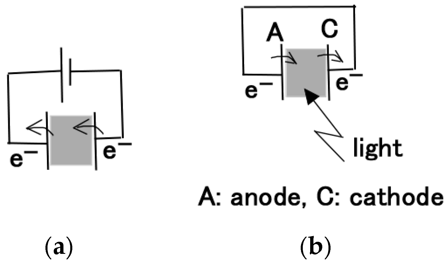
2.3. Chemical–Photovoltaic Mechanism

2.3.1. Case of Photovoltaic Mechanism by Dye and Electrolyte

The ordinary chemical–photovoltaic mechanism of DSSCs is well known and can be expressed as Equations (1)–(5).
At the cathode, the dye (Dye) is ionized to Dye+ with TiO2 coated on the transparent glass by illumination. Electrons from the dye enter the cathode through TiO2, which serves as an electron transport body.
At the anode, the electrolyte reacts as shown in Equation (1) by obtaining electrons from the anode. A part of I 3 reacts as shown in Equation (2).
3 I 2 + 2 e 2 I 3
2 I 3 + 2 e 3 I .
I 3 on the right side of Equation (1) transfers to the cathode and reduces the ionized Dye+ at the cathode as shown in Equation (3). The dye on the right side of Equation (3) is ionized to Dye+ at the cathode again as above. I2 on the right side of Equation (3) transfers to the anode and reacts as shown in Equation (1).
2 D y e + + 2 I 3 2 D y e + 3 I 2 .
On the other hand, at the cathode, I on the right side of Equation (2) reacts via photoexcitation as shown in Equations (4) and (5) such that the electrons enter the cathode. I2 on the right hand of Equation (5) transfers to the anode and reacts as shown in Equation (1).
3 I I 3 +   2 e .
2 I 3 3 I 2 + 2 e .
The above chemical–photovoltaic mechanism can be applied to ordinary DSSCs which are wet-type solar cells with liquid electrolyte and dye without any solid material. However, we can obtain the photovoltaic effect even if we use a conventional rubber sandwiched between the dye and the electrolyte solution, as shown in Figure 7 and in a previous study by Muller [29]. As a liquid, in general, cannot be percolated through a rubber, the creation of the photovoltaics might be due to the electrons and ions transferring over the rubber surface. In contrast, in the case of the MCF rubber DSSCs, a liquid can be percolated through MCF rubber as shown in Figure A2 in Appendix A, as presented in our previous study [41]. Therefore, the above chemical–photovoltaic mechanism occurs within the MCF rubber.

2.3.2. Case of Electrical–Chemical Mechanism before Electrolytic Polymerization and without Light Scattering

From our water-soluble rubber in the form of NR or CR structured by polyisoprene molecules in the MCF rubber, one unit of isoprene molecules is defined as SH with presenting S, as shown in Equation (6).
Energies 13 06658 i001.
Without electrolytic polymerization, SH is anionized to S, as shown in Equation (7), via the Honda–Fujishima effect [30,47].
S H ( S H ) * ( S H + ) * ( S H + ) S + H + .
S generates a radical as shown in Equation (8) via some influences such as illumination.
S S + e .
Water molecules are ionized as shown in Equation (9) [51].
H 2 O H + + O H .
The generated radical OH becomes a hydroxyl radical OH as shown in Equation (10) due to certain influences.
O H O H + e .

2.3.3. Case of Electrical–Chemical Mechanism by Electrolytic Polymerization and without Light Scattering

The reaction occurs as shown in Equation (11) at the anode via electrolytic polymerization [38].
S H + S S S + H + e .
SS denotes cross-linking between isoprene molecules. The reaction occurs as shown in Equation (12) at the cathode, when the oleic acid coating around Fe3O4 is defined by P as shown in Equation (13) [38].
P + H + + S + e S P H + e .
Energies 13 06658 i002
The electrons on the right side of Equations (10) and (11) transfer into the anode. The electron on the left side of Equation (12) transfers from the cathode and that on the right side transfers into the anode. Their transfers are delineated as shown in Figure 8a, which shows the electrical–chemical model of electrolytic polymerization. SPH denotes cross-linking between isoprene and oleic acid molecules. The hydroxyl radical OH is unstable enough to have a powerful oxidizing effect and, therefore, reacts with radical hydrogen H, as shown in Equation (14).
O H + H H 2 O .

2.3.4. Case of Photovoltaic Mechanism after Electrolytic Polymerization and with Light Scattering

In the case of solar cells under scattered light, reverse reactions of Equations (11) and (12) are generated as shown in Equations (15) and (16) under the outer-sphere electron transfer reaction (OSETR), which means that the structural coordination of molecules is not deformed and only the electrons are transferred by the tunneling effect [30].
S S + H + e S H + S .
S P H + e P + H + + S + e .
The electron on the left side of Equation (15) transfers from the anode. The electron on the left side of Equation (16) transfers from the anode and that on the right transfers into the cathode. S on the right side of Equations (15) and (16) generates the reaction shown in Equation (8), and then the electron on the right side of Equation (8) transfers into the cathode. These transfers are delineated as shown in Figure 8b, which depicts the chemical–photovoltaic mechanism of solar cells.

2.3.5. Case of Photovoltaic Mechanism by Catalyst Effect of TiO2, Ni, and Fe3O4.

Next, let us consider the catalyst effect of TiO2, Ni, and Fe3O4. Due to these catalysts, Equations (17) and (18) are created.
4 H + + H 2 O 2 H 2 + O 2 + 4 H + .
2 S + 2 H 2 O 2 S + H 2 + 2 O H .
H+ on the right side of Equation (17) creates Equation (19) and then Equation (14). The electron on the left side of Equation (19) transfers from the anode. OH on the right side of Equation (18) creates Equation (10).
H + + e H .
Additionally, upon electrolytic polymerization, the hydroxyl group of the oleic acid reacts with Ni as shown in Equations (20) and (21).
Energies 13 06658 i003.
Energies 13 06658 i004.
SPH is created from the right side of Equation (21) through Equation (12), and Ni2+ on the right side of Equation (20) is generated as shown in Equation (22) [52].
2 N i 2 + + 2 H 2 O 2 N i + O 2 + 4 H + .
H+ on the right side of Equation (22) creates Equation (19) and then Equation (14); the electron on the left side of Equation (19) transfers from the cathode via electrolytic polymerization and without light scattering; the electron on the left side of Equation (19) transfers from the anode via electrolytic polymerization and with light scattering.
On the other hand, upon electrolytic polymerization, Fe3O4 is generated as shown in Equations (23)–(27), where Fe (II) is FeO, Fe (III) is Fe2O3, and O2●− indicates superoxide radicals [53].
F e ( II ) + H 2 O 2 F e ( III ) + O H + O H .
F e ( III ) + H 2 O 2 F e ( O O H ) 2 + + H + .
F e ( III ) + H 2 O [ F e O H ] 2 + + H + .
F e ( II ) + O H F e ( III ) + O H .
F e ( II ) + O 2 F e ( III ) + O 2 .
In cases in which ultraviolet light is applied, Equation (28) is generated, followed by Equation (25). Then, Equation (26) is generated.
[ F e O H ] 2 + F e ( II ) + O H .
OH in Equations (23) and (26) creates Equation (14) through Equation (10); the electron on the right side of Equation (10) transfers into the anode via electrolytic polymerization and without light scattering; the electron on the left side of Equation (19) transfers into the cathode via electrolytic polymerization and with light scattering. H+ in Equations (24) and (25) creates Equations (12) and (19). H generated by Equation (19) creates Equation (14); the electron on the left side of Equation (19) transfers from the cathode via electrolytic polymerization and without light scattering; the electron on the left side of Equation (19) transfers from the anode via electrolytic polymerization and with light scattering.
Regarding other aspects, when the light is irradiated, the reactions below are generated with the TiO2 catalyst [54,55,56,57,58,59]. First, hole h+ and an electron are created from TiO2 as shown in Equation (29) [60].
T i O 2 h + + e .
This electron is scavenged by oxygen, and then superoxide radicals O2 are generated as shown in Equation (30) [61,62].
e + O 2 O 2 .
Hole h+ oxidizes molecules such as rubber or oleic acid, which are defined as R or R-H, as shown in Equation (31), and reacts with water as shown in Equations (32) and (33).
h + +   R R + .
4 h + + H 2 O 1 2 O 2 + 2 H + .
h + + H 2 O O H + H + .
Hydroxyl radical OH in Equation (33) oxidizes R-H and reacts with H as shown in Equation (14). As a result, molecules such as rubber or oleic acid are oxidized as shown in Equations (31) and (34) [63].
O H +   R   H   R + H 2 O .
The superoxide radicals O2 on the right side of Equation (30) are protonated, which means that proton H+ is ionized, thereby generating hydroperoxyl radicals HO2 as shown in Equation (35).
O 2 + H + H O 2 .
Hydrogen peroxide H2O2 is generated as shown in Equation (36) from the hydroperoxyl radicals HO2 on the right side of Equation (35).
2 H O 2 H 2 O 2 + O 2 .
In addition, hydrogen peroxide H2O2 is generated as shown in Equation (37) from the hydroperoxyl radicals O2 on the right side of Equation (30); the electron in Equation (37) is scavenged by O2.
2 N i 2 + + 2 H 2 O 2 N i + O 2 + 4 H + .
Summarizing from the above electrochemical reactions in Equations (4) and (5), in the case of light scattering, the creation of the photocurrent can be considered to correspond to the generating electrons as follows:
(a)
As shown in Equations (15) and (16), electrons transfer. Electrons are generated not only as shown in Equation (8) through S in Equations (15) and (16) but also as shown in Equation (19) through H+ in Equation (16). This chemical–photovoltaic mechanism is irrelevant to the behavior of the rubber molecule.
(b)
The operations expressed in Equations (19) and (21) are facilitated by the catalyst effect of TiO2, Ni, and Fe3O4 through the operations shown in Equations (17), (20), and (22). The ones expressed in Equation (10) are also facilitated through the one shown in Equation (18). This chemical–photovoltaic mechanism is irrelevant to the catalyst behavior of TiO2, Ni, and Fe3O4.
(c)
Equations (30) and (37) show that electrons are scavenged. This induces the reduction of photovoltaic current. In addition, not only Equations (17) and (18) but also Equations (9), (10), (14), and (19) show that the electrons are generated by water with an aiding catalyst. These summarized results provide the complicated changes in photovoltaic current. This chemical–photovoltaic mechanism is relevant to the behavior of correlation between TiO2 catalyst and H2O.
Thus, the photocurrent is created by summarizing the abovementioned operations (a–c) so that the photoelectricity is created as shown in the experimental data (e.g., Figure 7).
Incidentally, the photovoltaics of MCF rubber DSSCs are related to the integrated correlation as shown in many equations. The behavior of redox reactions of iodide and triiodide as shown in Equations (1) and (2) with respect to the overall reactions can be guessed via the comparison between Figure 3d,e and the results in our previous study [30] without using dye and electrolyte, as shown in Figure A3 in Appendix A. The role of iodide and the triiodide redox reaction is not diminutive.
Furthermore, concerning the chemical–photovoltaic mechanism, we could proceed with the photovoltaic theorem by using the theoretical formula of an equivalent electric circuit and tunneling theory as shown in our previous study [32] with conjugating Equations (1)–(37) in order to clarify the catalyst effect of TiO2, Ni, and Fe3O4, although we do not present that here.

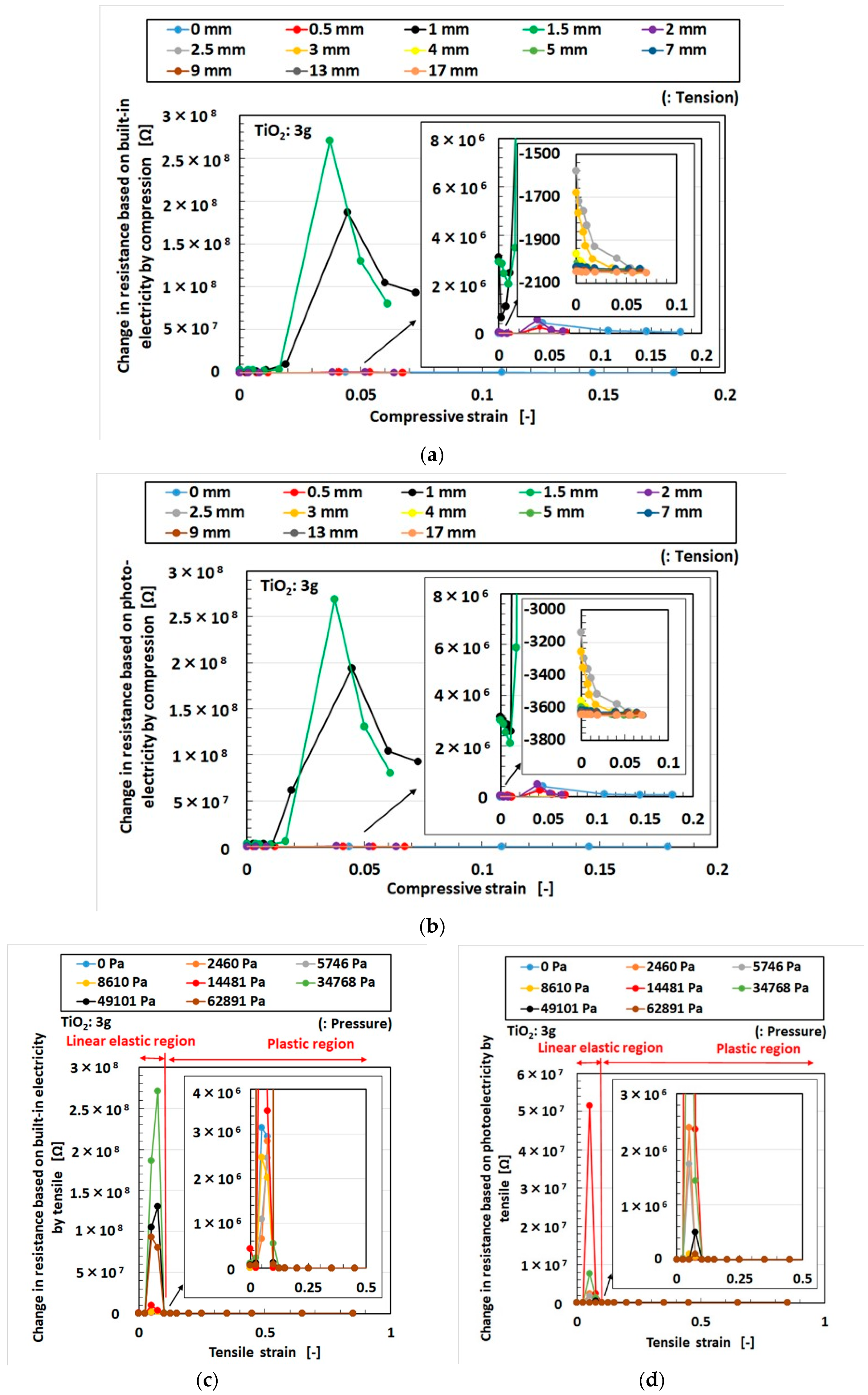
3. Effect of Tension and Compression

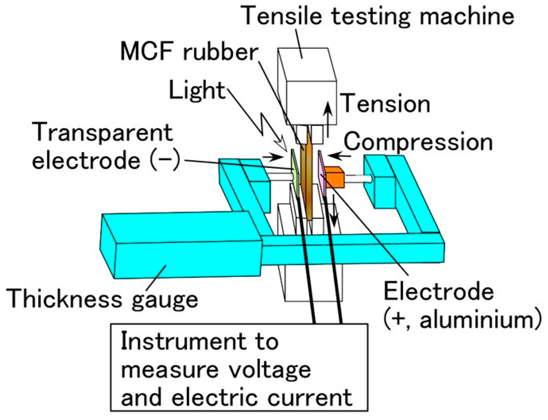
3.1. Experimental Procedure under Tension and Compression

We used the same experimental apparatus as in our previous studies [31] and as shown in Figure A4 in Appendix A. This apparatus provides tension and compression of MCF rubber DSSCs, as shown in Figure A1 (Appendix A), with 0.17 g of poured electrolyte solution and 0.06 g if poured liquid dye. The MCF rubber was elongated vertically by a small SL-6002 automatic measuring tensile testing machine (IMADA-SS) and, at the same time, was compressed by a thickness gauge transverse to the rubber, which was sandwiched by pieces of transparent glass (20 mm × 30 mm). For the compression, the irradiated glass coated with TiO2 was compressed by a cylinder with a φ 6.5 mm connected to the thickness gauge. Therefore, the irradiated area of the MCF rubber was the area that remained outside its circular area. The irradiation light was ultraviolet (40 Lux). The voltage and electric current between the electrodes were measured using a PC710 digital multimeter (Sanwa). The set-up is depicted in Figure 9. In the experiment, the MCF rubber was elongated not more than twice by tension and not more than half as many times by compression.

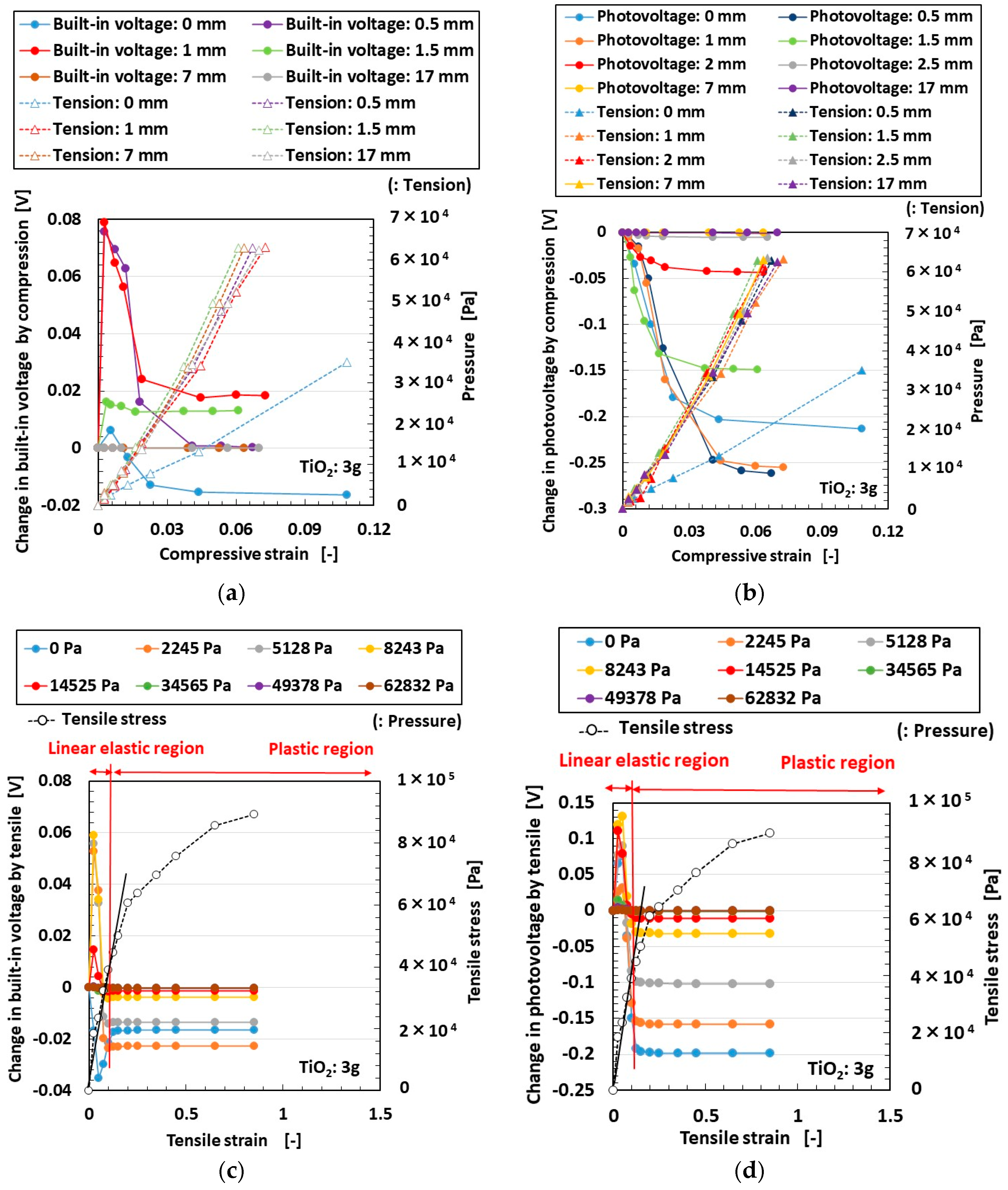
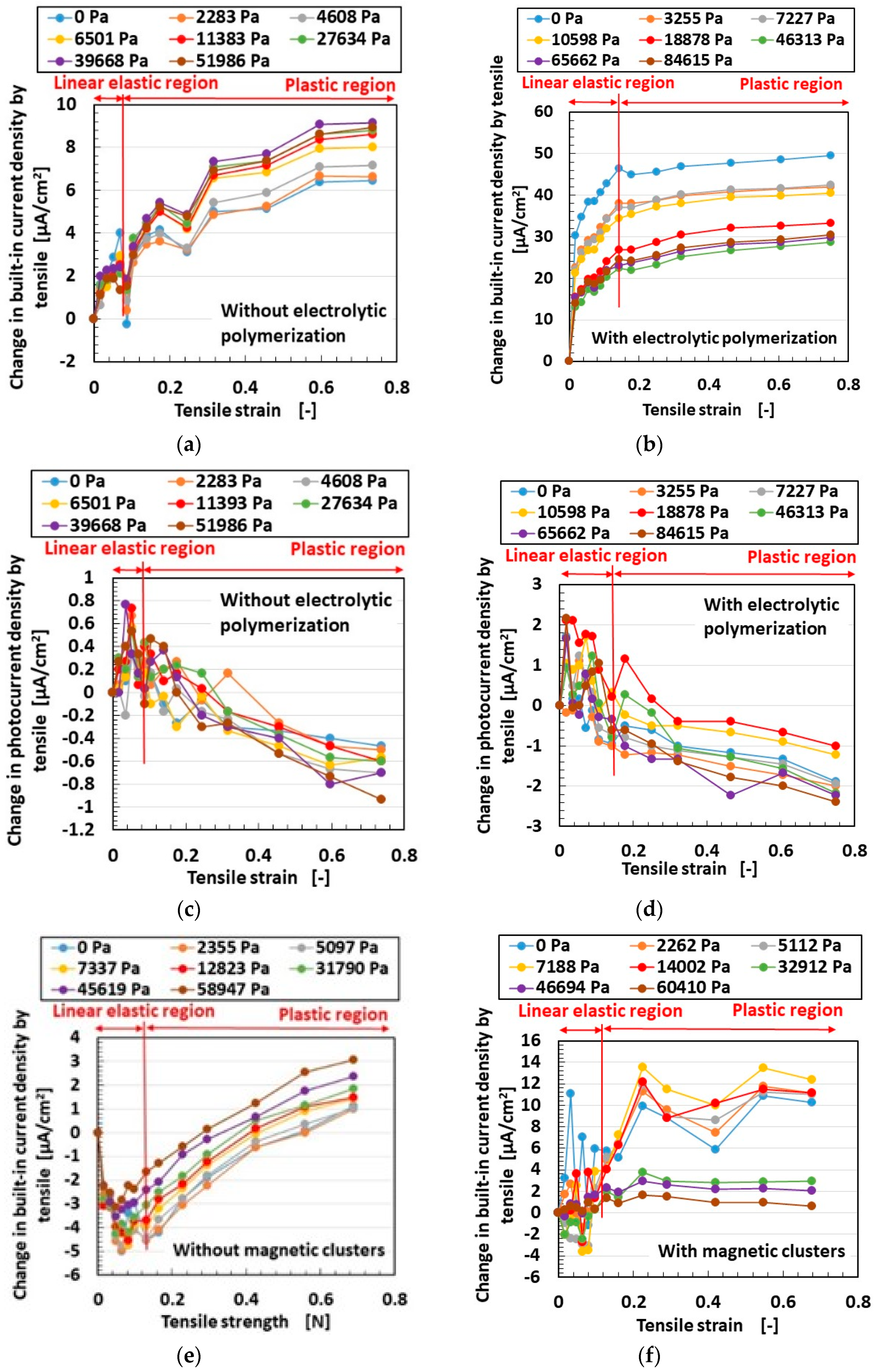
3.2. Results and Discussion

First of all, we clarified the length of conjugated double bond of MCF in our previous studies [34,38] as shown in Figure A5 in Appendix A, which is an example of electric current and tension. The length of the conjugated double bond lengthens via electrolytic polymerization and the application of a magnetic field. Therefore, through these factors, the photovoltaics are enhanced.
The effects of compression and tension on the built-in electricity and photoelectricity (for voltage and current density, respectively) and the electrical resistance corresponding to the built-in electricity and photoelectricity are shown in Figure 10, Figure 11 and Figure 12. These effects are presented as changes from the initial state (with neither compression nor tension) due to compression or tension. Here, the MCF rubber contained 3 g of TiO2, 6 g of Ni, 4.5 g of MF, and 9 g of NR latex. Where the compressive strain changed, the tension or tensile strain remained constant under the compression. Where the tensile strain changed, the pressure remained steady under the tension. If we consider the effect of either compression or tension individually, the case at 0 mm tensile stress or 0 Pa pressure is indicated in the figures. In the cases of voltage and electric current, the compressive strain–pressure relationship and the tensile strain–stress relationship are also shown (Figure 10 and Figure 11). While the former was only a linear relation, the latter had linear elastic and plastic regions.
Built-in voltage and current under increasing compression and tension tended to first increase and then decrease and remain constant. The enhancement occurred with the smallest compression or tension, and, in the case of tension, it occurred in the inner linear elastic region. On the other hand, while photovoltage and current under increasing tension showed the same tendency, under increasing compression, they showed a different tendency, without the initial increase. In contrast, regardless of condition, electrical resistance tended to show the first pattern, that is, an initial increase, followed by a decrease, after which values held constant. Figure 13 shows a microscopic model that explains these results, with electrons and holes bringing about photoelectricity and ions bringing about built-in electricity (Figure 5). The behaviors of the particles of Fe3O4, Ni, and TiO2, and the molecules of rubber, water, a mixture of potassium iodide (KI) and iodine (I2), and electrons as shown in Figure 5 are presented in Figure 13, and their configurations are different from those of ceramic and metal. Although the rubber prevented the particles and the molecules in Figure 13 from moving, the position of the particles and the molecules could move elastically in accordance with the rubber’s deformation via compression or tension. In the case of compression, as shown in Figure 13a, because the distance between the electron and the hole or between ions was narrowed, the voltage and electric current were increased. Under sequentially greater compression, the electron and hole became contiguous such that the voltage and electric current were zero, and, at further compression, the situation of the electron and hole was inverse such that the voltage and electric current attained negative values. On the other hand, in the case of tension (Figure 13b), because the distance between the electron and the hole or between ions was widened, the voltage and electric current decreased. However, the opposite situation could be considered to exist; that is, an adjacent electron and hole (“A” in Figure 13b) moved closer to each other due to reduced deformation transverse to the direction of tension. Therefore, the voltage and electric current potentially increased once.
Next, we investigated the effects of a TiO2 catalyst on built-in electricity and photoelectricity under compression and tension, as shown in Figure 14, Figure 15, Figure 16 and Figure 17. Here, the MCF rubber contained 2, 4, or 5 g of TiO2, 6 g of Ni, 4.5 g of MF, and 9 g of NR latex. As in Figure 10, Figure 11 and Figure 12, the tension remained constant under compression, and the pressure remained constant under tension. Changes due to compression or tension are shown as differences from the initial state (with neither compression nor tension).
Under compression, the built-in current tended to show values that changed from positive to negative as TiO2 increased, while, in the case of photocurrent, negative values tended to decrease as TiO2 increased. These results indicate that the enhancement of TiO2 reduced the built-in current and photocurrent by compression. This can be explained by the model in Figure 13a, where ionized particles increased with increasing TiO2, and the adjacent ionized particles approached each other and became contiguous such that the voltage and electric current became zero due to compression.
On the other hand, under tension, built-in current tended to show values that changed from negative to positive as TiO2 increased, while positive photocurrent values tended to decrease to zero with increasing TiO2. These results indicate that the enhancement of TiO2 increased built-in current values but decreased photocurrent values due to tension. This can be explained by the model in Figure 13b, where the adjacent ionized electron and hole (“A” of built-in electricity in Figure 13b) approached each other due to the reduced deformation under tension such that the voltage and electric current were enhanced; however, the adjacent electrons and holes that emerged from neutral particles and molecules (“A” of photoelectricity in Figure 13b) approached each other such that the voltage and electric current became zero due to tension.

4. Conclusions

As TiO2 increases, the area surrounded by the IV curve becomes small and MCF rubber DSSCs serve almost as photodiodes. Electrical resistance depends on the amount of TiO2. As TiO2 increases, the electrical resistance as piezo-resistivity at the initial zero pressure decreases; however, the electrical resistance under the greatest pressure increases and, therefore, the difference decreases.
Built-in voltage and current under increasing compression and tension tend to first increase, then decrease, and then remain steady. The increase occurs under the smallest amount of compression or tension and, in the case of tension, occurs in the linear elastic region. Photo voltage and current under increasing tension show the same tendency as above; however, under increasing compression, they do not show the initial increase in values. In contrast, regardless of condition, electrical resistance tends to first increase, then decrease, and then remain constant. Regarding compression, increasing TiO2 reduces the changes in built-in current and photocurrent, while, in the case of tension, increasing TiO2 increases the change in built-in current but reduces the change in photocurrent.
The particles and molecules in MCF rubber DSSCs are ionized, corresponding to A and D+. In addition, the present experimental results regarding the effect of TiO2 on photovoltaics can be explained by the chemical–photovoltaic mechanism involving the behavior of dye, electrolyte solution, water, and rubber molecules and the catalytic effect of Ni and Fe3O4 on the MCF, TiO2, and K, together with the Honda–Fujishima effect. To summarize the chemical reactions in the case of light scattering, the creation of the photocurrent comes about by generating electrons; the chemical–photovoltaic mechanism is irrelevant to the behavior of rubber molecules where the operations of electrons are facilitated by the catalyst of TiO2, Ni, and Fe3O4.
Because ordinary solar cells do not have the properties of large tension or compression, they are rigid and not very flexible, and solar cells having these properties are currently novel enough to be almost unknown. However, MCF rubber DSSCs typically have large tension and compression, and their production opens the door to a number of practical devices and instruments. MCF rubber solar cells are suitable for a great variety of engineering applications. Once they are ready to go into production, the present experimental results and the model of the chemical–photovoltaic mechanism will be of great interest. For further development of the MCF rubber DSSCs, large stretchable transparent glass needs to be developed because large stretchable MCF rubber DSSCs integrated with stretchable transparent glass bring about more practical and convenient devices and instruments. The study to develop the large stretchable transparent glass will be addressed in another investigation.

Author Contributions

For this research article, K.S. conceptualized the idea, designed and performed the experiments, analyzed the data, and wrote the paper; H.K., R.I., and H.T. contributed reagents/materials/analysis tools and analyzed the data. All authors have read and agreed to the published version of the manuscript.

Funding

This work was supported in parts by JSPS KAKENHI Grant Number JP 18K04040 and by the Fukushima Innovation Coast Framework project “Namie Town Creation with Revitalizics using Risk Communication Engineering: for Realization of Innovation Coast Framework” in Japan.

Conflicts of Interest

The funding sponsors had no role in the design of the study. The authors declare no conflict of interest.

Appendix A

Figure A1 is a schematic diagram of the experimental procedure of fabricating the MCF rubber DSSCs after electrolytic polymerization [31].
Figure A1. Schematic diagram of the fabrication of MCF rubber DSSCs [31].
Energies 13 06658 g0a1
Ordinary solid rubber such as vulcanized NR or Q is generally impermeable. However, any liquid can permeate electrolytically polymerized MCF rubber, as shown in the experiment in Figure A2, which used a 312 mT magnetic field, a 30 V electric field, and 2.7 A for 5 min with a 1 mm gap between electrodes [41]. MCF rubber can be permeated not only in the form of water-soluble rubber types such as NR or CR but also as a mixture of water-soluble and water-insoluble rubber types such as Q with MCF. As shown in Figure A2b, water can be seen as a shimmering reflection of light on the rubber surface after permeation.
Figure A2. Images of MCF rubber before and after water permeation (0.75 g of MF, 0.5 g of TiO2, 3 g of S-500, 3 g of 671A, and 3 g of Ni): (a) before permeation; (b) after permeation [41].
Energies 13 06658 g0a2
Figure A3 shows the changes in voltage and electric current density when ultraviolet light was turned on and off without dye and KI + I2 [30]. In the figure, “elec.” indicates electrolytic polymerization, “mag.” indicates a magnetic field at electrolytic polymerization, and “no-” indicates their absence.
Figure A3. Change in voltage and electric current density of the MCF rubber DSSCs without dye and KI + I2 by illumination vs. non-illumination: (a) voltage; (b) electric current density [30].
Energies 13 06658 g0a3
Figure A4 shows the experimental apparatus used to investigate the effect of the simultaneous excitation of tension and compression on the photovoltaics of MCF rubber DSSCs. This is the same apparatus we used in our previous study [31].
Figure A4. Schematic diagram of experimental apparatus for measuring the built-in electricity and photoelectricity of MCF rubber DSSCs under tension and compression [31].
Energies 13 06658 g0a4
Figure A5 shows the effects of the electrolytic polymerization and the application of a magnetic field on built-in electricity and photoelectricity under tension. Here, the MCF rubber contained 6 g of Ni, 4.5 g of MF, and 9 g of NR latex.
Figure A5. Effects of tension on the electric current as built-in electricity and photo electricity; (a,b,e,f) for built-in electricity; (c,d,g,h) for photo electricity; (a,c) without electrolytic polymerization; (b,d) with electrolytic polymerization; (e,g) without the application of a magnetic field; (f,h) with the application of a magnetic field; (ad) at 5 g of TiO2; (eh) at 4 g of TiO2.
Energies 13 06658 g0a5aEnergies 13 06658 g0a5b

References

  1. Chen, C.P.; Chiang, C.Y.; Yu, Y.Y.; Hsiao, Y.S.; Chen, W.C. High-performance, robust, stretchable organic photovoltaics using commercially available tape as a deformable substrate. Sol. Energy Mat. Sol. Cells 2017, 165, 111–118. [Google Scholar] [CrossRef]
  2. Cong, H.N.; Dieng, M.; Sene, C.; Chartier, P. Hybrid organic-inorganic solar cells: Case of the all thin film PMeT(Y)/CdS(X) junctions. Sol. Energy Mat. Sol. Cells 2000, 63, 23–35. [Google Scholar] [CrossRef]
  3. Kudo, N.; Shimazaki, Y.; Ohkita, H.; Ohoka, M.; Ito, S. Organic–inorganic hybrid solar cells based on conducting polymer and SnO2 nanoparticles chemically modified with a fullerene derivative. Sol. Energy Mat. Sol. Cells 2007, 91, 1243–1247. [Google Scholar] [CrossRef]
  4. Maruthamuthu, P.; Fiechter, S.; Tributsch, H. Lipid (detergent)-based composite-dye solar cell. C. R. Chim. 2006, 9, 684–690. [Google Scholar] [CrossRef]
  5. Won, S.C.; Sung, H.A.; Harim, J.; Yong, G.S.; Jong, H.K. Rubbery copolymer electrolytes containing polymerized ionic liquid for dye-sensitized solar cells. J. Solid State Electrochem. 2012, 16, 3037–3043. [Google Scholar]
  6. Gamstedt, H.; Hagfeldt, A.; Kloo, L. Photoelectrochemical studies of ionic liquid-containing solar cells sensitized with different polypyridyl-ruthenium complexes. Polyhedron 2009, 28, 757–762. [Google Scholar] [CrossRef]
  7. Guo, L.; Pan, X.; Wang, M.; Zhang, C.; Fang, X.; Chen, S.; Dai, S. Novel hydrophobic ionic liquids electrolyte based on cyclic sulfonium used in dye-sensitized solar cells. Sol. Energy 2011, 85, 7–11. [Google Scholar] [CrossRef]
  8. Rastogi, A.C.; Janardhana, N.R. Properties of CuSbS2 thin films electrodeposited from ionic liquids as p-type absorber for photovoltaic solar cells. Thin Solid Film. 2014, 565, 285–292. [Google Scholar] [CrossRef]
  9. Zhai, P.; Lee, H.; Huang, Y.T.; Wei, T.C.; Feng, S.P. Study on the blocking effect of a quantum-dot TiO2 compact layer in dye-sensitized solar cells with ionic liquid electrolyte under low-intensity illumination. J. Power Sources 2016, 329, 502–509. [Google Scholar] [CrossRef]
  10. Gadilohar, B.; Shankarling, G.S. Choline based ionic liquids and their applications in organic transformation. J. Mol. Liq. 2017, 227, 234–261. [Google Scholar] [CrossRef]
  11. Han, X.; Wang, Y.; Zhu, L. The performance and long-term stability of silicon concentrator solar cells immersed in dielectric liquids. Energy Convers. Manag. 2013, 66, 189–198. [Google Scholar] [CrossRef]
  12. Tsubomura, H.; Matsumura, M.; Nomura, Y.; Amamiya, T. Dye sensitized zinc oxide: Aqueous electrolyte platinum photocell. Nature 1976, 261, 402–403. [Google Scholar] [CrossRef]
  13. Su’ait, M.S.; Rahman, M.Y.A.; Ahmad, A. Review on polymer electrolyte in dye-sensitized solar cells (DSSCs). Sol. Energy 2015, 115, 452–470. [Google Scholar] [CrossRef]
  14. O’regan, B.; Gratzel, M. A low-cost, high-efficiency solar cell based on dye-sensitized colloidal TiO2 films. Nature 1991, 353, 737–740. [Google Scholar] [CrossRef]
  15. Kojima, A.; Teshima, K.; Shirai, Y.; Miyasaka, T. Organometal halide perovskites as visible-light sensitizers for photovoltaic cells. J. Am. Chem. Soc. 2009, 131, 6050–6051. [Google Scholar] [CrossRef] [PubMed]
  16. Arbab, A.A.; Ali, M.; Memon, A.A.; Sun, K.C.; Choi, B.J.; Jeong, S.H. An all carbon dye sensitized solar cell: A sustainable and low-cost design for metal free wearable solar cell devices. J. Colloid Int. Sci. 2020, 569, 386–401. [Google Scholar] [CrossRef]
  17. Jung, J.W.; Bae, J.H.; Ko, J.H.; Lee, W. Fully solution-processed indium tin oxide-free textile-based flexible solar cells made of an organic-inorganic perovskite absorber: Toward a wearable power source. J. Power Source 2018, 402, 327–332. [Google Scholar] [CrossRef]
  18. Brosseau, C. Emerging technologies of plastic carbon nanoelectronics: A review. Surf. Coat. Technol. 2011, 206, 753–758. [Google Scholar] [CrossRef]
  19. Kaltenbrunner, M.; Sekitani, T.; Reeder, J.; Yokota, T.; Kuribara, K.; Tokuhara, T.; Drack, M.; Schwodiauer, R.; Graz, I.; Gogonea, S.B.; et al. An ultra-lightweight design for imperceptible plastic electronics. Nature 2013, 499, 458. [Google Scholar] [CrossRef]
  20. Savagatrup, S.; Printz, A.D.; Wu, H.; Rajan, K.M.; Sawyer, E.J.; Zaretski, A.V.; Bettinger, C.J.; Lipomi, D.J. Viability of stretchable poly (3-heptylthiophene)(P3HpT) for organic slar cells and field-effect transistors. Synth. Met. 2015, 203, 208–214. [Google Scholar] [CrossRef]
  21. Reinoso, J.; Paggi, M.; Areias, P. A finite element framework for the interplay between delamination and buckling of rubber-like bi-material systems and stretchable electronics. J. Eur. Ceram. Soc. 2016, 36, 2371–2382. [Google Scholar] [CrossRef]
  22. Ma, R.; Feng, J.; Yin, D.; Sun, H.B. Highly efficient and mechanically robust stretchable polymer solar cells with random buckling. Org. Electron. 2017, 43, 77–81. [Google Scholar] [CrossRef]
  23. Liu, K.; Wei, A.; Liu, J.; Liu, Z.; Xiao, Z.; Zhao, Y. NiCo2S4 nanosheet thin film counter electrodes prepared by a two-step approach for dye-sensitized solar cells. Mater. Lett. 2018, 217, 185–188. [Google Scholar] [CrossRef]
  24. Guo, X.; Xu, Z.; Huang, J.; Zhang, Y.; Liu, X.; Guo, W. Photoelectrochromic smart windows powered by flexible dye-sensitized solar cell using CuS mesh as counter electrode. Mater. Lett. 2019, 244, 92–95. [Google Scholar] [CrossRef]
  25. Yun, S.; Lim, S. Improved conversion efficiency in dye-sensitized solar cells based on electrospun Al-doped ZnO nanofiber electrodes prepared by seed layer treatment. J. Solid State Chem. 2011, 184, 273–279. [Google Scholar] [CrossRef]
  26. Wang, B.; Chen, Z.; Zhang, J.; Cao, J.; Wang, S.; Tian, Q.; Gao, M.; Xu, Q. Fabrication of PVA/graphene oxide/TiO2 composite nanofibers through electrospinning and interface sol-gel reaction: Effect of graphene oxide on PVA nanofibers and growth of TiO2. Colloids Sur. A Phys. Eng. Asp. 2014, 457, 318–325. [Google Scholar] [CrossRef]
  27. Yun, M.J.; Cha, S.I.; Seo, S.H.; Lee, D.Y. Highly flexible dye-sensitized solar cells produced by sewing textile electrodes on cloth. Sci. Rep. 2014, 4, 5322. [Google Scholar] [CrossRef] [Green Version]
  28. Hsieh, Y.T.; Chen, J.Y.; Shih, C.C.; Chueh, C.C.; Chen, W.C. Mechanically robust, stretchable organic solar cells via buckle-on-elastomer strategy. Org. Electron. 2018, 53, 339–345. [Google Scholar] [CrossRef]
  29. Muller, S.; Wieschollek, D.; Junger, I.J.; Helkamp, E.S.; Ehrmann, A. Back electrodes of dye-sensitized solar cells on textile fabrics. Optik 2019, 198, 163243. [Google Scholar] [CrossRef]
  30. Shimada, K. Elastic MCF rubber with photovoltaics and sensing for use as artificial or hybrid skin (H-Skin): 1st report on dry-type solar cell rubber with piezoelectricity for compressive sensing. Sensors 2018, 18, 1841. [Google Scholar] [CrossRef] [Green Version]
  31. Shimada, K. Elastic MCF rubber with photovoltaics and sensing on hybrid skin (H-Skin) for artificial skin by utilizing natural rubber: 2nd report on effect of tension and compression on properties of hybrid photo- and piezo-electricity in wet-type solar cell rubber. Sensors 2018, 18, 1848. [Google Scholar] [CrossRef] [PubMed] [Green Version]
  32. Shimada, K. MCF rubber with photovoltaics and sensing for use as artificial or hybrid skin (H-Skin): Third report on electric charge and storage under tension and compression. Sensors 2018, 18, 1853. [Google Scholar] [CrossRef] [PubMed] [Green Version]
  33. Shimada, K.; Kato, R.; Ikeda, R.; Kikura, H.; Takahashi, H. γ-ray irradiation effect on MCF rubber solar cells with both photovoltaics and sensing involving semiconductors fabricated under magnetic and electric fields. World J. Mech. 2020, 10, 95–119. [Google Scholar]
  34. Shimada, K.; Saga, N. Mechanical enhancement of sensitivity in natural rubber using electrolytic polymerization aided by a magnetic field and MCF for application in haptic sensors. Sensors 2016, 16, 1521. [Google Scholar] [CrossRef] [Green Version]
  35. Shimada, K.; Saga, N. Detailed mechanism and engineering applicability of electrolytic polymerization aided by a magnetic field in natural rubber by mechanical approach for sensing (Part 1): The effect of experimental conditions on electrolytic polymerization. World J. Mech. 2016, 6, 357–378. [Google Scholar] [CrossRef] [Green Version]
  36. Shimada, K.; Saga, N. Detailed mechanism and engineering applicability of electrolytic polymerization aided by a magnetic field in natural rubber by mechanical approach for sensing (Part 2): Other and intrinsic effects on MCF rubber property. World J. Mech. 2016, 6, 379–395. [Google Scholar] [CrossRef] [Green Version]
  37. Shimada, K.; Saga, N. Development of a hybrid piezo natural rubber piezoelectricity and piezoresistivity sensor with magnetic clusters made by electric and magnetic field assistance and filling with magnetic compound fluid. Sensors 2017, 17, 1521. [Google Scholar] [CrossRef] [Green Version]
  38. Shimada, K. Enhancement of MCF rubber utilizing electric and magnetic fields, and clarification of electrolytic polymerization. Sensors 2017, 17, 767. [Google Scholar] [CrossRef] [Green Version]
  39. Shimada, K.; Michizuki, O.; Kubota, Y. The effect of particles on electrolytically polymerized thin natural MCF rubber for soft sensors installed in artificial skin. Sensors 2017, 17, 896. [Google Scholar] [CrossRef] [Green Version]
  40. Shimada, K.; Ikeda, R.; Kikura, H.; Takahashi, H. Development of a magnetic compound fluid rubber stability sensor and a novel production technique via combination of natural, chloroprene and silicone rubbers. Sensors 2019, 189, 3901. [Google Scholar] [CrossRef] [Green Version]
  41. Shimada, K.; Ikeda, R.; Kikura, H.; Takahashi, H. Enhancement of diversity in production and application utilizing electrolytically polymerized rubber sensors with MCF: 1st report on consummate fabrication combining varied kinds of constituents with porous permeant stocking-like rubber. Sensors 2020, 20, 4658. [Google Scholar] [CrossRef]
  42. Shimada, K.; Ikeda, R.; Kikura, H.; Takahashi, H. Enhancement of diversity in production and application utilizing electrolytically polymerized rubber sensors with MCF: The second report on various engineering applications. Sensors 2020, 20, 4674. [Google Scholar] [CrossRef]
  43. Miettunen, K.; Toivola, M.; Hashmi, G.; Salpakari, J.; Asghar, I.; Lund, P. A carbon gel catalyst layer for the roll-to-roll production of dye solar cells. Carbon 2011, 49, 528–532. [Google Scholar] [CrossRef] [Green Version]
  44. Gurulakshmi, M.; Meenakshamma, A.; Susmitha, K.; Charanadhar, N.; Srikanth, V.V.S.S.; Babu, S.N.; Subbaiah, Y.P.V.; Venkateswarlu, K.; Raghavender, M. A transparent and Pt-free all-carbon nanocomposite counter electrode catalyst for efficient dye sensitized solar cells. Sol. Energy 2019, 193, 568–575. [Google Scholar] [CrossRef]
  45. Qian, X.; Xu, C.; Jiang, Y.; Zhang, J.; Guan, G.; Huang, Y. Ni-Co-MoSx ball-in-ball hollow nanoshperes as Pt-free bifunctional catalysts for high-performance solar cells and hydrogen evolution reactions. Chem. Eng. J. 2019, 368, 202–211. [Google Scholar] [CrossRef]
  46. Li, J.; Yun, S.; Han, F.; Si, Y.; Arshad, A.; Zhang, Y.; Chidambaram, B.; Zafar, N.; Qiao, X. Biomass-derived carbon boosted catalytic properties of tungsten-based nanohybrids for accelerating the triiodide in dye-senstitized slar cells. J. Colloid Interfaces Sci. 2020, 578, 184–194. [Google Scholar] [CrossRef] [PubMed]
  47. Fujishima, A.; Honda, K. Electrochemical photolysis of water at a semiconductor electrode. Nature 1972, 238, 37–38. [Google Scholar] [CrossRef] [PubMed]
  48. Bashir, R.; Makhdoom, A.R.; Bilal, M.K.; Badar, M.A. Comparative study of the photovoltaic behavior of ruthenium and the other organic and inorganic Dye-Sensitized Solar Cells (DSSC). Optik 2018, 157, 11–15. [Google Scholar] [CrossRef]
  49. Buffa, M.; Carturan, S.; Debije, M.G.; Quaranta, A.; Maggioni, G. Dye-doped polysiloxane rubbers for luminescent solar concentrator systems. Sol. Eng. Mater. Sol. Cells 2012, 103, 114–118. [Google Scholar] [CrossRef]
  50. Nyberg, T.; Zhang, F.; Inganas, O. Macromolecular nanoelectronics. Curr. Appl. Phys. 2002, 2, 27–31. [Google Scholar] [CrossRef]
  51. Vannucci, A.K.; Alibabaei, L.; Losego, M.D.; Concepcion, J.J.; Kalanyan, B.; Parsons, G.N.; Meyer, T.J. Crossing the divide between homogeneous and heterogeneous catalyst in water oxidation. Proc. Natl. Acad. Sci. USA 2013, 110, 20918–20922. [Google Scholar] [CrossRef] [PubMed] [Green Version]
  52. Iwasawa, Y. Tailored Metal Catalysts; D. Reidel Publishing Company: Dordrecht, The Neverlands, 1986; pp. 167–172. ISBN 90-277-1866-0. [Google Scholar]
  53. Duran, A.; Monteagudo, J.M.; Martin, I.S. Operation costs of the solar photo-catalytic degradation of pharmaceuticals in water: A mini-review. Chemosphere 2018, 211, 482–488. [Google Scholar] [CrossRef] [PubMed]
  54. Sun, H.; Bai, Y.; Jin, W.; Xu, N. Visible-light-driven TiO2 catalysts doped with low-concentration nitrogen species. Sol. Energy Mater. Sol. Cells 2008, 92, 76–83. [Google Scholar] [CrossRef]
  55. Ito, S.; Nazeeruddin, K.M.; Zakeeruddin, S.M.; Pechy, P.; Comte, P.; Gratzel, M.; Mizuno, T.; Tanaka, A.; Koyanagi, T. Study of dye-sensitized solar cells by scanning electron micrograph observation and thickness optimization of porous TiO2 electrodes. Int. J. Photoenergy 2009, 2009, 517609. [Google Scholar] [CrossRef]
  56. Iyas, A.M.; Gondal, M.A.; Baig, U.; Akhtar, S.; Yamani, Z.H. Photovoltaic performance and photocatalytic activity of facile synthesized graphene decorated TiO2 monohybrid using nanosecond pulsed ablation in liquid technique. Solar Energy 2016, 137, 246–255. [Google Scholar]
  57. Lu, W.H.; Chou, C.S.; Chen, C.Y.; Wu, P. Preparation of Zr-doped mesoporous TiO2 particles and their applications in the novel working electrode of a dye-sensitized solar cell. Adv. Powder Technol. 2017, 28, 2186–2197. [Google Scholar] [CrossRef]
  58. Shamsudin, N.H.; Shafie, S.; Kadir, M.Z.A.A.; Ahmad, F.; Sadrolhosseini, A.R.; Sulaiman, Y.; Chachuli, S.A.M. Power conversion efficiency (PCE) performance of back-illuminated DSSCs with different Pt catalyst contents at the optimized TiO2 thickness. Optik 2020, 203, 163567. [Google Scholar] [CrossRef]
  59. Haimeur, A.E.; Makha, M.; Bakkali, H.; Leal, J.M.G.; Blanco, E.; Dominguez, M.; Voitenko, Z.V. Enhanced performance of planar perovskite solar cells using dip-coated TiO2 as electron transporting layer. Sol. Energy 2020, 195, 475–482. [Google Scholar] [CrossRef]
  60. Maksoud, Y.K.A.; Imam, E.; Ramada, A.R. TiO2 water-bell photoreactor for wastewater treatment. Sol. Energy 2018, 170, 323–335. [Google Scholar] [CrossRef]
  61. Qin, G.; Wu, Q.; Sun, Z.; Wang, Y.; Luo, J.; Xue, S. Enhanced photoelectrocatalytic degradation of phenols with bifunctionalized dye-sensitized TiO2 film. J. Hazard. Mater. 2012, 199–200, 226–232. [Google Scholar] [CrossRef]
  62. Monteagudo, J.M.; Duran, A.; Chazisymeon, E.; Martin, I.S.; Naranjo, S. Solar activation of TiO2 intensified with graphene for degradation of Bisphenol-A in water. Sol. Energy 2018, 174, 1035–1043. [Google Scholar] [CrossRef] [Green Version]
  63. Etacheri, V.; Valentin, C.D.; Schneider, J.; Bahnemann, D.; Pillai, S.C. Visible-light activation of TiO2 photocatalysts: Advances in theory and experiments. J. Photochem. Photobiol. C Photochem. Rev. 2015, 25, 1–29. [Google Scholar] [CrossRef] [Green Version]
Figure 1. Images of fabricated magnetic compound fluid (MCF) rubber dye-sensitized solar cells (DSSCs): (a) transparent glass on the anode size of the DSSC; (b) glass on the cathode side of the DSSC, coated with TiO2.
Energies 13 06658 g001
Figure 2. The surface of electrolytically polymerized MCF rubber with TiO2: (a) anode side of the electrode during electrolytic polymerization with 2 g of TiO2; (b) cathode side of the electrode during electrolytic polymerization with 2 g of TiO2; (c) anode side of the electrode during electrolytic polymerization with 4 g of TiO2; (d) cathode side of the electrode during electrolytic polymerization with 4 g of TiO2.
Energies 13 06658 g002
Figure 3. Effect of TiO2 on the voltage, electric current, and resistance of MCF rubber DSSCs as a function of illumination vs. non-illumination: (a) voltage, visible light; (b) electric current, visible light; (c) electrical resistance, visible light; (d) voltage, ultraviolet light; (e) electric current, ultraviolet light; (f) electrical resistance, ultraviolet light.
Energies 13 06658 g003
Figure 4. The effect of TiO2 on the current–potential curves of MCF rubber under illumination: (a) visible light; (b) ultraviolet light.
Energies 13 06658 g004
Figure 5. Model of the generation of photoelectricity and built-in electricity.
Energies 13 06658 g005
Figure 6. The effect of TiO2 on piezo-resistivity, piezo-electricity, and photoelectricity: (a) electrical resistance as piezo-resistivity to pressure; (b) electrical resistance as piezo-resistivity to TiO2; (c) voltage as photoelectricity and built-in electricity; (d) electric current as photoelectricity and built-in electricity; (e) electrical resistance with photoelectricity and built-in electricity.
Energies 13 06658 g006
Figure 7. The effect of TiO2 on changes in the voltage, electric current, and resistance of PSECR DSSCs upon illumination and termination of illumination: (a) voltage, visible light; (b) electric current, visible light; (c) electrical resistance, visible light; (d) voltage, ultraviolet light; (e) electric current, ultraviolet light; (f) electrical resistance, ultraviolet light.
Energies 13 06658 g007
Figure 8. Model of electron transfer: (a) during electrolytic polymerization; (b) at solar cells.
Energies 13 06658 g008
Figure 9. Photograph of the experimental apparatus for measuring the built-in electricity and photoelectricity of MCF rubber DSSCs under tension and compression.
Energies 13 06658 g009
Figure 10. Effects of compression and tension on voltage as built-in electricity and photoelectricity: (a) as built-in electricity, under compression; (b) as photoelectricity, under compression; (c) as built-in electricity, under tension; (d) as photoelectricity, under tension.
Energies 13 06658 g010
Figure 11. Effects of compression and tension on the electric current as built-in electricity and photoelectricity: (a) as built-in electricity, under compression; (b) as photoelectricity, under compression; (c) as built-in electricity, under tension; (d) as photoelectricity, under tension.
Energies 13 06658 g011
Figure 12. Effects of compression and tension on the electrical resistance as built-in electricity and photoelectricity: (a) as built-in electricity, under compression; (b) as photoelectricity, under compression; (c) as built-in electricity, under tension; (d) as photoelectricity, under tension.
Energies 13 06658 g012
Figure 13. Model of the effects of compression and tension on the photoelectricity created by electrons and holes emerging from neutral particles and molecules (Figure 5) and on the built-in electricity created by ionized particles and molecules after the emergence of electrons and holes: (a) by compression; (b) by tension.
Energies 13 06658 g013
Figure 14. Effects of compression on the electric current as built-in electricity: (a) at 2 g of TiO2; (b) at 4 g of TiO2; (c) at 5 g of TiO2.
Energies 13 06658 g014aEnergies 13 06658 g014b
Figure 15. Effects of compression on the electric current as photoelectricity: (a) at 2 g of TiO2; (b) at 4 g of TiO2; (c) at 5 g of TiO2.
Energies 13 06658 g015
Figure 16. Effects of tension on the electric current as built-in electricity: (a) at 2 g of TiO2; (b) at 4 g of TiO2; (c) at 5 g of TiO2.
Energies 13 06658 g016
Figure 17. Effects of tension on the electric current as photo electricity: (a) at 2 g of TiO2; (b) at 4 g of TiO2; (c) at 5 g of TiO2.
Energies 13 06658 g017aEnergies 13 06658 g017b
Publisher’s Note: MDPI stays neutral with regard to jurisdictional claims in published maps and institutional affiliations.

