Solid State Transformers: Concepts, Classification, and Control
by
 , , , , and
Mohammed Azharuddin Shamshuddin
1 ,
,
Felix Rojas
2,*,
Roberto Cardenas
3 ,
,
Javier Pereda
4,
Matias Diaz
2 and
and
Ralph Kennel
1 1
Institute of Electric Drive Systems and Power Electronics, Technische Universität München, 80333 Munich, Germany
2
Department of Electrical Engineering, Universidad de Santiago de Chile, 8320000 Santiago, Chile
3
Department of Electrical Engineering, Universidad de Chile, 8320000 Santiago, Chile
4
Department of Electrical Engineering, Pontificia Universidad Católica de Chile, 7500000 Santiago, Chile
*
Author to whom correspondence should be addressed.
Energies 2020, 13(9), 2319; https://doi.org/10.3390/en13092319
Submission received: 16 March 2020
/
Revised: 13 April 2020
/
Accepted: 22 April 2020
/
Published: 7 May 2020
(This article belongs to the Special Issue Control Strategies for Power Conversion Systems)
Abstract
:Increase in global energy demand and constraints from fossil fuels have encouraged a growing share of renewable energy resources in the utility grid. Accordingly, an increased penetration of direct current (DC) power sources and loads (e.g., solar photovoltaics and electric vehicles) as well as the necessity for active power flow control has been witnessed in the power distribution networks. Passive transformers are susceptible to DC offset and possess no controllability when employed in smart grids. Solid state transformers (SSTs) are identified as a potential solution to modernize and harmonize alternating current (AC) and DC electrical networks and as suitable solutions in applications such as traction, electric ships, and aerospace industry. This paper provides a complete overview on SST: concepts, topologies, classification, power converters, material selection, and key aspects for design criteria and control schemes proposed in the literature. It also proposes a simple terminology to identify and homogenize the large number of definitions and structures currently reported in the literature.
1. Introduction
Passive transformers have been indispensable components in electrical power systems since Zipenowsky et al. demonstrated the first commercial transformer in 1885 [1,2]. Later, Tesla proposed the application of transformers for an electrical distribution system in 1888 [3]. Even though passive transformers can achieve voltage regulation through tap changers, solid state transformers (SSTs), also known as power electronic transformers (PETs), are capable of compensating voltage sags and harmonic distortion, interconnecting asynchronous networks, interfacing DC and AC port(s), compensating reactive power, regulating voltage magnitude, isolating disturbances from source and load or vice versa, and eliminating the use of mechanical actuators or tap changers. These features make SST a very attractive solution to replace passive low frequency transformers (LFTs) in several applications [4]. However, SSTs should not explicitly be implied as a complete replacement of LFTs as they may not be feasible in certain applications (e.g., special transformers such as instrument transformers or phase shifting transformers) [5,6]. Thus, feasibility of an SST should be adjudged based on the application and economic viability.
The concept of SST was first proposed in 1970 by William McMurray as a high frequency link AC/AC power converter [7]. However, the first introduction of the term SST was as an alternative to auto-transformer based on an AC/AC buck converter and AC/AC buck-boost converter, which was proposed by J.L.Brooks in 1980 for naval systems [8,9]. It is in 1999 that the capability of an SST as a distribution transformer was reported in a patent by Sudhoff et al. [10] and also in a publication by Moonshik Kang et al. [11]. In 2001, Lothar Heinemann et al. [12] proposed the utilization of SSTs as a universal power electronics based distribution transformer for medium voltage/low voltage (MV/LV) distribution systems. Recently, there has been renewed interest in SSTs due to a growing demand for interfacing AC and DC medium voltage levels using power converters of high power density with high performance and controllability in applications such as traction and future smart grids [13,14]. Owing to medium frequency of operation, SSTs have a reduced volume and weight, achieving higher power density and smaller footprint. In addition, the declining costs and increased availability of high performance low-voltage (LV) semiconductor devices, as well as advances in new magnetic materials with higher saturation flux density and lower specific core losses have contributed for SSTs to be technically and economically feasible, attracting the global research interest.
SSTs are characterized by three main features: (1) Connection to at least one medium voltage (MV) (or high voltage (HV)) port (either AC or DC); (2) Medium frequency isolation stage(s), and (3) Controllability over input and/or output electrical parameters [4,13]. Recently, a communication (COMM) port is also being demanded as one of the key features of SSTs [15,16]. SSTs have quickly evolved and numerous topologies have been proposed and named as SSTs. However, only topologies which satisfy these three key features are considered as an SST and are included in this review (communication port is not considered as a mandatory feature of SSTs).
SSTs have found numerous areas of acceptance such as: smart grids [17,18,19,20] due to its controllability over voltage, current and frequency; it has a complete control on active and reactive power. In addition, due to its high switching frequency, it can match high dynamic requirements for harmonic filtering. SSTs are also capable of providing grid ancillary services such as islanding detection, grid isolation, on-grid operation, and hybrid and autonomous mode of operation with energy management in local micro/nano-grids [21]. SSTs are envisioned to be utilized as energy routers in the future envisioned power system network [15] and even in the future sub-sea power distribution network [22]. Furthermore, SST applications can be extended for soft-open-points (SOPs) in distribution network system as it allows parallel connection of an SST with a passive transformer of different rated powers and can provide active and reactive power flow control under normal operation [23]. SSTs provide fault isolation and voltage/supply restoration under abnormal conditions. Moreover, galvanic isolation with DC port(s) help to integrate electric vehicles (EVs) and may facilitate fast charging of EVs [24], energy storage systems and integrate renewable energy sources like solar photovoltaics [25], wind energy [26], and micro hydro-power systems. Thereby, an SST functioning as isolated MVAC/LVDC conversion can be used in critical loads such as data centers [14]. Due to their reduced footprint and low weight, SSTs are also suitable for the upcoming traction systems with distributed propulsion and low profile vehicles with top mounted traction equipment [13,27,28]. Applications of SSTs can further be extended to MVDC electric ships [29], aircraft power systems [30,31], and also for underground power distribution substations, where there is space limitation benefiting from SST’s reduced volume to weight ratio [32,33].
SSTs can be utilized with the existing power distribution networks without requiring replacement or expansion of the current electrical infrastructure. Various industries are working on SSTs such as ABB, Switzerland; General Electric Co., U.S.; Alstom SA, France; Mitsubishi Electric Corporation, Japan; Siemens AG, Germany; Schneider Electric SE, France; and Cooper Power Systems, Brazil [34]. A few startups namely working on SSTs are Varentec, U.S. and Amantys, U.K. with the latter being focused on wind farm applications [35]. The global growth rate of the SST-market is forecasted to expand at a compound annual growth rate (CAGR) of 21.7% from 2019 to 2027 with Europe being projected to lead the market with a CAGR of 23.4% [36]. Thus, the growing adaptation of SSTs in academia and industry point SST as a next revolutionary step in the power electronics community.
In this work, an overview of SST is presented, discussing and classifying its concepts, topologies, and applications. The paper is organized as follows: Section 2 introduces the SST architectures and proposes a terminology for a simple classification. Section 3 presents the composition of SSTs using the proposed SST nomenclature. In Section 4, an overview on various classifications and sub-classifications of SSTs are reported. Section 5 details available power converter topologies for interfacing MV and LV side of the SST along with a brief review on the modulation schemes. Section 6 reviews the constructive aspects of SSTs in terms of semiconductor selection and design criteria of a medium frequency transformer (MFT). In Section 7, control schemes for the most relevant SST applications are reviewed. Section 8 presents safety and protection issues for SSTs. Finally, brief concluding remarks and future trends are presented in Section 9.
2. SST Architecture
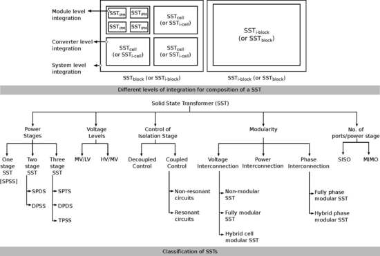
The architecture of SSTs has been classified based on number of power conversion stages and electrical features that compose it, as first proposed by Lothar Heinemann et al. in [12] and illustrated in Figure 1. This classification was adopted by Xu She et al. in [37] with the single stage without DC-link being referred as type A, two stages with LV DC-link as type B, two stages with HV (or MV) DC-link as type C, and three stages with MV and LV DC-link as type D. However, considering the current state of the art on SSTs, this classification is not wide enough and several of the reported SST topologies are not covered by this classification. Thus, a simple and intuitive terminology for a universal classification of SSTs is proposed in this work. The terminology is based on the three key characteristics that define an SST i.e., connection to MV or HV at least in one port, MF isolation stage, and control of input/output electrical variables, being sufficiently general to include any kind of SST.
Figure 2 shows the proposed definition of two different groups of power conversion stages, for simplicity named as solid state transformer block () and solid state transformer isolated block (), which can be considered as the building blocks for any SST. Thereby, the corresponds to an isolated power conversion unit with connection to MV or HV levels while the corresponds to a non-isolated power conversion unit, which ports can be indistinctly connected to LV and/or MV range. The by itself satisfies the three key characteristics to be termed as an SST. Therefore, represents the simplest form of an SST, i.e., a single stage SST. Single stage SSTs have a single port available at the primary and at the secondary side of the MFT. Accordingly, various single stage SSTs can be sub-classified as: single primary single secondary (SPSS) AC‖AC SST, SPSS AC‖DC SST, SPSS DC‖AC SST, and SPSS DC‖DC SST as shown in Figure 2a–d, where the symbol ‖ stands for the identification of the galvanic isolation. Thereby, can be considered as extension stages of to form different configurations of SSTs.
Two-stage SST can be constructed using one and one . This interconnection generates a coupling link, which will be considered as a port only if it is intended for external interconnection; otherwise, it is just considered as an energy link. Thereby, based on the placement of the , an additional port can be created either at the primary side of MFT for back-end or at the secondary side of the MFT for front-end . Accordingly, SST topology in Figure 1b,c can be defined as dual primary single secondary (DPSS) AC/DC‖AC SST and single primary dual secondary (SPDS) AC‖DC/AC SST, respectively. Authors in [16] presented an isolated front-end SST configuration with an AC link and reduced complexity and volume for MV converters, which is presented in Figure 3a. Although this topology is not contained into the classification presented in the literature (see Figure 1), based on the proposed terminology, it is defined as SPDS AC‖AC/DC SST. Supposing that the AC link is not intended for external interconnection, then the topology should be named as SPSS AC‖AC/DC SST. This clarifies that the SST is intended only for one AC input port and one DC output port, having an AC interlink after the .
Likewise, a three-stage SST such as Figure 1d is formed using one and two forming a dual primary dual secondary (DPDS) AC/DC‖DC/AC SST. Furthermore, authors in [38] proposed a three-stage SST named as a bidirectional intelligent semiconductor transformer as shown in Figure 3b, aimed for smart distribution systems and microgrids. Using the proposed terminology, this can be referred as a single primary triple secondary (SPTS) AC‖DC/DC/AC SST.
Thereby, an SST with any number of stages can be easily classified. Interconnection of two or more will be considered as interconnection of separate SSTs, unless all the and are controlled as a single unit, without independent control for each block. In that case, the terminology remains unchanged and the symbol ‖ shall denote the number of within the SST.
The concept presented in Figure 2 has assumed only one input and one output port per , i.e., SISO . Nevertheless, as presented in Figure 4, the concept can be extended for (s) with multiple input multiple output (MIMO) ports. Thereby, MIMO blocks can interface an arbitrary number of m-input(s) and supply energy to n-output ports. Notice that the voltage ports for MIMO in Figure 4a–d share the same nature (i.e., AC or DC). It is also possible to construct a MIMO with voltage ports of different nature (i.e., AC and DC) defined as hybrid-port MIMO and is shown in Figure 4e—thus completing the generality of the proposed terminology.
3. Composition of an SST
Figure 5 shows the different levels of integration to understand the composition of an SST. As it was previously discussed, generation of different SST architectures can be achieved using the combination of the defined and . The definition of these architectures have been made in a system level of integration. In order to further identify and classify the different topologies of SSTs proposed in the literature, it is required to look into the proposed and presented in Figure 2 and establish some definitions regarding its construction. Figure 5 defines the three different levels of integration. Firstly, the concept of integrated power modules (IPM) [40] is used, which is defined as the smallest self-contained power electronic unit. Thus, an IPM (also known as power electronics building block (PEBB)), defined as a module integration level, is composed of semiconductor devices, gate drivers, sensors, protections, power supplies, communication ports, passive elements, and the required circuitry to create one module. A typical example of an IPM would be one leg of a power converter. When an IPM is used to create an SST, it will be named as solid state transformer integrated power modules (). Likewise, and as shown in Figure 5, the interconnection of forms a so called solid state transformer cell (), if an MFT is used within the interconnection, they form a solid state transformer isolated cell (). This represents the next level of integration, namely power converter integration level. Finally, the interconnection of one or more (or ) defines a (or ). Thus, the complexity of a (or ) is defined by the number of in each (or ) and the number of (or ) in each the (or ).
3.1. Module Integration Level
At the module integration level, an can take any form. Commonly, commercially available integrated power modules are used to create a . Thereby, an could be a half bridge phase leg, matrix converter phase leg [41], or a multi-level converter phase leg or a cascaded H-bridge (CHB) or modular multilevel converter (MMC) phase leg as shown in Figure 6.
3.2. Converter Integration Level: SISO Configuration-I
Standard and non-standard power electronics converters can be used at the converter level integration. This integration leads to the construction of and , which are further explored in this section.
A is composed of either a single , i.e., a single power converter, as shown in Figure 7a, or it can be formed by using multiple units . Typically, interconnection of several are required to handle the high levels of voltage or current present at the terminals of an SST. Series interconnection helps to achieve high voltage levels with LV semiconductors. Similarly, parallel interconnection is suitable for handling high current levels. Accordingly, three different interconnections can be highlighted: input series output series (ISOS), input series output parallel (ISOP), and input parallel output parallel (IPOP) connection, as depicted in Figure 7b–d.
A topological equivalent model of is shown in Figure 7e. Similarly, an is formed using one MFT only and its topological equivalent model is shown in Figure 7f. It is composed of an MFT placed in-between primary side and/or secondary side (s) (only one is required). A reactive high frequency network is usually present at the primary and secondary side of the MFT to control energy transfer, create resonance, and allow soft-switching operation on [50,51]. The MFT not only provides galvanic isolation but also produces large voltage and current transfer ratios with high efficiency.
An is composed of either a single or using multiple connected in ISOS or ISOP configuration as shown in Figure 7a–c. Notice that an formed using a single has a single and centralized MFT [4,52], while an formed using multiple possesses several distributed MFTs [53,54]. The MFT implemented in an (see Figure 7f) can have several configurations, as shown in Figure 8a–f. These different MFT configurations can be used in the same manner to create an as presented in Figure 9.
3.3. Converter Integration Level: SISO Configuration-II
A single can be combined with additional (s) to extend the stages at the cell-level as shown in Figure 10a–c. Additionally, multiple units of multi-stage can be interconnected in ISOP or ISOS configuration to distribute the voltage or current burden as shown in Figure 10d,e respectively. It is noteworthy that the multi-stage as shown in Figure 3 has a common DC-link unlike multi-stage as in Figure 10d,e that has multiple isolated and independent DC ports.
3.4. Converter Integration Level: MIMO Configuration
MIMO is composed of multiple units of either or multi-stage which are interconnected to create multiple input and/or output ports to achieve additional degree of freedom in terms of power routing. A three port MIMO formed using and multi-stage is shown in Figure 11a,b. Furthermore, Figure 11c shows a hybrid-port MIMO SST topology.
4. Classification of SSTs:
SSTs are classified based on: (a) power stages, (b) voltage levels, (c) control of the isolation stage, (d) modularity, and (e) number of ports per power stage as illustrated in Figure 12.
4.1. SST Classification Based on Voltage Levels
According to the key characteristics of an SST [13], at least one port of the SST has to be connected to MV, either AC or DC. Thus, regarding its voltage levels, the following classifications can be defined: (a) MV/LV configuration and (b) HV/MV configuration.
Figure 13a shows the MV/LV SST configuration, a low frequency (LF) MV input is interfaced at the primary side port of the SST which is processed either using a single or multiple . The primary side (s), which may also possess an MV DC-link, increases the frequency to provide medium frequency (MF) voltage to the primary side of the MFT, which, besides providing isolation, reduces the voltage magnitude. Depending on the power electronics structure and application, a frequency range of 1 kHz to several hundred kHz can be implemented. Similarly, the secondary side (s) provides LVAC and/or LVDC output. An extensive assessment of MV and LV voltage level standards is presented in [12]. Most of the publications related to SSTs are reported for MV/LV voltage levels, being an attractive and economically viable solution to interface electrical systems to medium voltage levels mainly in modern traction and smart grid technologies [48,49].
In addition, in Figure 13b, typical applications of SSTs adopted in high voltage (HV) levels such as offshore wind turbines for HVDC/MVAC configuration are reported in [59,61,62]. For this application, the lower weight/volume ratio of SSTs compared to passive transformers is a key feature which makes SST economically attractive. Moreover, authors in [60] have emphasized this benefits in HV/MV distribution grid highlighting faster replacement and cost for transporting SST using truck as compared to railways for a standard HV transformer.
Furthermore, the definition of medium voltage is wide and may be interpreted differently based on different national and/or international grid codes [63]. Table 1 depicts the voltage ranges defined in the IEC 60038 [64]. German standard BDEW 2008 defines the MV range for distributed energy resources (DER) connected to MV network ranging from 1 kV to 66 kV [65] and, in France, the medium voltage level could be referred to HVA range (>1 kV to <50 kV) as voltage levels below 1 kV are defined as low voltage in [66].
4.2. SST Classification Based on Control of Isolation Stage
SSTs can be classified based on control of the (or isolation stage) namely [67,68]: (a) Decoupled control of isolation stage and (b) Coupled control of isolation stage.
4.2.1. Decoupled Control of Isolation Stage
In this type of control, the primary and secondary side as shown in Figure 7f are controlled independently without utilizing the MFT’s reactive network placed at the primary and/or secondary side of the MFT. The transformer acts as a passive element and transforms voltage appearing across its primary winding. In fact, the earliest proposal of Moonshik Kang et al. in [11] demonstrated voltage regulation using this approach. The phase shift angle (), which is the phase difference between the switching signals of the primary and secondary side , is set to zero. In addition, authors highlighted that no energy storage element was utilized. Similarly, a decoupled control of isolation stage is reported in [4,52].
4.2.2. Coupled Control of Isolation Stage
The coupled control of isolation stage utilizes primary and secondary side along with the reactive network as shown in Figure 7f. Reactive network is required, which is used for energy transfer, achieving current shaping and soft switching [50]. Two different circuits are reported [67,68] namely: (a) Non-resonant circuits and (b) Resonant circuits.
Isolation Stage Based on Non-Resonant Circuits
The concept of non-resonant based energy transfer can be associated with the principle of dual active bridge (DAB) which was first introduced by De Doncker et al. in 1991 [69] for high power density isolated DC/DC conversion as highlighted in Figure 14a. The reactive network consists of a series connected leakage inductance connected to the MFT, which is utilized for temporary energy storage allowing to control a phase shift angle () between input and output voltages. It is also possible to achieve non-resonant based isolated DC/DC conversion using isolated push–pull topology [70] or using current doubler topology as reported in [71]. An extensive classification of isolated DC/DC converters with their topologies and modulations is detailed by Florian Krismer in [50].
Authors in [72] presented an isolated AC/AC stage as shown in Figure 14b. The control of this topology is based on principle of DAB; authors refer to it as an AC/AC DAB for SST and demonstrated energy transfer, voltage regulation, and soft switching using the non-zero leakage inductance. Furthermore, the author in [73] highlights the limitations to achieve zero voltage switching (ZVS) in AC/AC DAB as it requires additional auxiliary circuits to extend the ZVS range.
Authors in [68] presented a soft switching SST formed using an isolated AC/AC stage constructed using current source bridges and operating as a DAB. This topology utilizes transformer magnetizing inductance instead of the leakage inductance for energy transfer, and this topology is referred to as dynamic current converter or dyna C in [74] and is shown in Figure 14c. Authors in [75] highlighted several complex manufacturing issues in adopting a three phase isolated DC/DC DAB in SSTs as the three phase transformer requires symmetrical leakage inductances. In addition, optimizing performance using advanced modulation schemes such as those based on triangular or trapezoidal waveforms may not be feasible for a three-phase DAB. Therefore, single phase isolated DC/DC DAB stages are the most commonly adopted topology in multi-cell SSTs.
Falcones et al. in [76] adopted multiple active bridge (MAB) in SST, namely quad active bridge (QAB), as shown in Figure 14d aimed to integrate distributed generation and energy storage systems. Furthermore, Costa et al. in [77] highlights the benefits of MAB as they are reported to preserve the advantages of DAB and offer an additional advantage of reduced number of transformers and modules. Extensive details of various multi-port isolated DC/DC converters are found in [78].
Isolation Stage Based on Resonance Circuits
The concept of resonant converters was first proposed by Schwarz in 1970 [79]. The primary side reactive high frequency network is usually composed of leakage inductance with a combination of series and/or parallel inductor and/or capacitor to form: series resonant converter (SRC), parallel resonant converter (PRC), hybrid series-parallel LCC and LLC type to achieve medium frequency isolated DC/DC transformation [68], and this is shown in Figure 15a–d. A bidirectional power flow in resonant converters can be achieved using active devices in the secondary bridge and controlling the phase angle () between the input and output voltages [68,80]. An example of coupled control in isolation stage using resonant circuits can be seen in [38], which utilizes an LLC based isolated AC/DC power conversion stage as shown in Figure 15e.
Isolated DC/DC conversion using SRC in discontinuous-conduction mode is reported to provide a well regulated power over a wide loading range with minimal sensors [19]. In addition, the half-cycle discontinuous-conduction mode (HC-DCM) SRC has received more attention in SST due to higher power density, efficiency, and possibility to implement soft switching methods [81]. Unlike DAB, the performance of SRC depends of the accuracy of the resonance frequency of the circuit, which might change as passive components age or load changes worsening its performance. Thus, DAB has emerged as a preferred choice over SRC especially for SSTs in distributed systems [55]. Therefore, the selection of isolation stage based on resonance or non-resonance circuit depends on the application.
4.3. SST Classification Based on Modular Structure
Kolar et al. in [49] presented three degrees of freedom in terms of modularity defined based on: direction of power flow, connection to 3-phase system, and connection to the MV voltage levels. A similar concept is extended to the proposed SST concept (see Figure 2) and is defined as: (a) modularization based on direction of power flow (P-axis), (b) modularization based on voltage/current levels (V-axis), and (c) modularization based on phase interconnection (-axis).
Modularization in the direction of power flow is achieved by adding (s) to create additional power stages such as two-stage or three-stage SSTs, thereby obtaining additional degrees of freedom in control and interfacing ports e.g., the presence of a DC-link for decoupling the low frequency and high frequency side [49]. Figure 16 shows the degree of modularization along the P-axis. Notice that the (or ) along the P-axis alone are formed using single (or ) only.
Modularization based on voltage/current levels is defined based on no. of (or ) per power stage (see Section 3.2) and can be sub-classified as: (a) non-modular SSTs, (b) hybrid-cell SSTs, and (c) fully modular multi-cell SSTs as shown in Figure 17. Figure 17b highlights a hybrid-cell SPDS SST with an formed using multiple units of and a formed using single unit of and its placement on the PV-plane is highlighted.
Modularization based on phase interconnection is achieved in n-phase AC systems either in the electric circuit using single phase to n-phases by replicating it symmetrically or in the magnetic circuit using single phase MFT. Modularization in the -axis can be sub-classified as: (a) non-modular SST, (b) semi-phase modular SST, and (c) fully phase modular SST, and is shown in Figure 18.
Modularity achieves scalability and redundancy. Therefore, it is crucial for SST as it ensures system reliability and simplifies mass production consequently, achieving lower production costs. The three-dimensional (PV-plane) for previous research works is illustrated in Figure 19. A comparative review of functional capabilities of previous SST topologies is found in [82]. The following sub-sections present a review of previous publications for these sub-classifications.
4.3.1. Modularity Based on Direction of Power Flow
Most of the earliest single stage SSTs proposed in the literature were mainly demonstrated for low voltage levels. Authors in [83] adapted the proposed topology and concept of McMurray [7] and demonstrated phase modulation using single phase matrix converters for a 3 kVA transformer. Authors in [11] presented a similar topology for a single phase 10 kVA, 240/246 V electronic transformer along with a multilevel approach. Authors in [84] proposed symmetric modulation scheme to achieve soft transitions for this topology. Similarly, the earliest proposed SPSS AC‖DC SST as shown in Figure 2b was presented by authors in [85] using a phase control methodology aimed for Uninterruptible Power Supplies (UPS) systems. Recently, authors in [57] highlighted single stage SPSS AC‖AC SST for a 7.2 kV input and reported a few limitations such as absence of DC-link which may require an increased size of filters consequently, affecting the input power factor.
Furthermore, authors in [86] demonstrated a two-stage DPSS AC/DC‖AC SST as illustrated in Figure 1b to address power quality issues such as: power factor correction, voltage regulation, voltage sag and swell elimination, and voltage flicker reduction. Typically, this configuration of SST can be employed in MVDC based electric ships or in DC collectors for large scale PV plant [29,87,88,89]. Additionally, authors in [4] presented a two-stage SPDS AC‖DC/AC SST as shown in Figure 1c aimed at four-wire power distribution networks utilizing MMC for SST and reported that the topology had a reduced footprint and elements in the SST validating through a dynamic model and decoupled control system. The author in [90] reported the feasibility and advantages of a three-stage DPDS AC/DC‖DC/AC SST as shown in Figure 1d over a conventional transformer using a simulation model.
4.3.2. Modularity Based on a Voltage/Current Level
Figure 20a–c shows different fully modular and hybrid-cell modular SST configurations as reported in the literature. Authors in [91] demonstrated a fully modular multi-cell SPSS AC‖AC SST as shown in Figure 20a; the cells are interconnected in an ISOP configuration to form a 10 kVA 7.2 kV/120 V SST. Similarly, authors in [58] presented a PET aimed for traction as shown in Figure 20b and these both can be classified as fully modular SST. The SST presented as a patent by Sudhoff et al. in [10] can be defined as a hybrid cell modular SST as shown in Figure 20c. Authors in [92] report utilizing phase shedding technique i.e., activating or deactivating (s) based on system operating point could improve efficiency but is detrimental to system reliability as it increases the thermal stress. Therefore, authors propose a power routing concept to implement active thermal control through unevenly loaded to enhance system efficiency and increase the lifetime.
4.3.3. Modularity Based on Phase Interconnection
Figure 21 illustrates a fully phase modular SST as demonstrated by authors in [54] using seven level three-phase cascaded H-bridge converters in back to back configuration, each consists of an isolated DC/DC converter placed in-between two H-bridges. Similarly, Lai et al. in [93] presented a 4.16 kV/480 V fully phase-modular SST referring it as intelligent universal transformer (IUT) aimed at medium voltage applications.
Furthermore, authors in [53] presented a 1 MVA 10 kV/400V hybrid-phase modular SST and have highlighted the suitability of HC-DCM SRC in isolated DC/DC module for phase-modular SSTs as they are reported to achieve high operating efficiency. Authors have also highlighted its limitations such as inability to control the power flow and further proposed mitigation strategies to overcome propagation of single phase power fluctuation through HC-DCM SRC due to dynamic coupling in the DC/DC stage.
Authors in [55] reviewed phase modular SSTs as shown in Figure 22 and presented an inter-phase modular SST topology as shown in Figure 22d. Authors claim a better fault management capability in inter-phase modular topologies as compared to phase modular topology (see Figure 22c). To implement redundancy, a phase modular configuration would need three additional (one from each phase) as compared to inter-phase modular SST which would need only one additional .
5. Power Converter Topologies and Modulation Schemes
Power converter (s), embedded in the (s), are a key element for the operation of an SST. They synthesize the required voltage and currents, modulating and demodulating high frequency AC voltages across the MFT windings. Power converters, augmented with suitable control systems, are also required to eliminate low frequency signals in the MFT which otherwise would saturate its magnetic core. This section details various power converter topologies suitable for SST applications, which are classified based on the voltage operating range, namely: (1) MV side (s) and (2) LV side (s).
5.1. MV (or HV) Side (s)
There are four different methodologies reported in the literature [19,32,48,90] which are used to interface the MV voltage level, namely: (a) series connected LV semiconductor devices, (b) wide band gap based semiconductor devices, (c) multilevel converters, and (d) multi-cell approach. The present available rating for LV-IGBT is around 1700 V. A possible means to interface MV levels using a two-level bridge structure (Figure 6a) and LV semiconductor devices is by series connection of LV devices; however, dynamic voltage balancing is a challenging task [48]. Furthermore, additional snubber circuits make this approach less attractive as compared with other solutions.
Recently, with the availability of wideband gap semiconductor devices such as the 15-kV/10A SiC MOSFET and the 15-kV/20A SiC IGBTs [95], it is possible to adopt two-level bridge structures for lower MV levels; however, for higher MV levels, there may still be a need to connect these devices in series. Authors in [95] have carried out an analysis for series connected SiC IGBTs and SiC MOSFETs on the MV side for a DAB, the series connected 10-kV SiC MOSFET displays very low power dissipation up to 50 kHz switching frequency as compared to the 15-kV SiC IGBT; however, additional snubber circuits are required for making this approach due to lower voltage blocking capability.
Furthermore, a two level bridge structure as a topology to reach MV levels has worse harmonic performance compared to multilevel converters. Therefore, multilevel converters with wideband gap semiconductor devices seem a better candidate for interfacing MV levels. Among the multilevel converters, most widely used topologies are namely: (a) Neutral Point Clamped (NPC) or Diode Clamped [42,43]; (b) Flying Capacitor (FC) [44]; (c) Cascaded H-Bridge (CHB) [46,96,97]; and (d) Modular Multilevel Converter (MMC) [47].
The NPC topology is generally adopted as three levels (Figure 6d) and practically feasible up to five levels [13]. At higher output voltage levels, there may be challenges in capacitor voltage balance and also a requirement of several series connected diodes resulting in higher conduction losses. Gabriel Ortiz in [32] has presented a detailed design of a power-cell using isolated a DC/DC converter comprised of an NPC half bridge leg on the MV side and full bridge on the LV side for 2 kV/400 V transformation. Krishna Mainali et al. in [56] have demonstrated a DPDS AC/DC‖DC/AC SST with the MV side formed by three-level NPC in a back-to-back configuration using 15-kV SiC switches for power substation application.
The FC is in principle similar to the NPC; the main difference is that the clamping diodes are replaced by flying capacitors [98]. A large number of capacitors allows voltage ride through during short outages and voltage sags. For a higher number of voltage levels, FC converters require a large amount of storage capacitor and the system tends to be bulky and expensive. Even though the NPC and FC can be adopted in modular SSTs, but they are not modular and scalable for high voltage levels.
The CHB is a type of multilevel converter which is modular and formed by a series connection of H-bridge cells wherein each H-bridge cell is connected to an individual DC source. Authors in [99] have analyzed modular power converters utilized in SSTs, i.e., CHB and MMC, and highlight that, in a CHB configuration with no DC voltage to supply, its cells have limited performance in terms of reactive power and harmonic compensation and usually the cells’ capacitor voltage in such configurations are maintained close to a target average voltage. Most of the SST configurations adopting CHB topologies are either in fully phase modular configuration [54] or hybrid cell modular configuration [94,100]. Authors in [94] have presented a qualitative comparison for a CHB cascaded with a dual active bridge (DAB) and quad active bridge (QAB); authors report a cost savings in semiconductors alone of US $2,350.08 for using QAB instead of DAB. However, QAB presents higher control complexities. Furthermore, authors in [100] present an startup procedure for CHB based hybrid-phase modular three stage SST. A distinctive feature of CHB topology is its inability to provide a common MVDC and/or LVDC port [19].
Finally, the MMC is a recent multilevel converter topology [47]. Unlike CHB, MMC requires no individual DC voltage supply; instead, it uses floating capacitors for energy transfer and is modular in nature. An MMC could be a better candidate as compared to the other multilevel converter topology on the MV (or HV) side due to its robust and modular nature whilst obtaining an improved power quality [4,101,102,103,104].
5.2. LV Side (s)
This group of converters usually interface the load end and are connected to the secondary winding of the MFT. Direct matrix or indirect matrix converters may be adopted without series connected semiconductor devices for AC/AC conversion. As for the DC-link based converters, the secondary bridge is mostly a 2-level full bridge or half bridge configuration. Furthermore, the back-end inverter can either be a 2-level or a 3-level NPC voltage source inverter based on the application. In addition, the back-end inverter is capable of interfacing four wire AC output using four leg converters. Authors in [105,106] have presented extensive details on four-leg converters and its control.
5.3. Modulation Schemes
It is essential to understand available modulation schemes for the configurations discussed in the above sub-section. One of the earliest reviews on matrix converters can be traced to Wheeler et al. [107] in 2002 and similar reviews on AC/AC conversion and control are found in [108,109]. A review on control and modulation for matrix converters is explained in detail in [41,110]. Furthermore, authors in [111] have detailed various modulation techniques for multilevel converters.
Additionally, the most commonly adopted modulation scheme in a DAB is a single phase shift (SPS) modulation or rectangular modulation which operates the DAB at a constant frequency and a fixed duty cycle of primary (D1) and secondary side (D2) as 50%. The power flow in this technique is established by controlling the phase shift angle ( ) between the primary and secondary bridges, which, in turn, controls the voltage induced across the leakage inductance, thereby achieving power control from leading to lagging bridge [50,89,112]. Although this technique is simpler and achieves high power flow along with high dynamics, it has limited soft-switching range and possesses a large transformer root mean square (RMS) current. To reduce the semiconductor turn off losses, Schibli in [112] discussed a trapezoidal and triangular current modulation scheme. In a trapezoidal modulation scheme, a blanking time is added to the switching cycle whereby four switches can achieve soft-switching. There are two switches on the MV side and two on the LV side consequently, reducing the switching losses and achieving slightly higher efficiency. However, it is unable to operate when the secondary voltage is zero, i.e., for no-load condition and is not suitable for low loading conditions. In addition, it possesses an unsymmetrical share of losses on the half bridge for unequal voltage levels. In case of triangular modulation, which is a special case of trapezoidal modulation, one of the voltage edges of the primary and secondary is overlapped thereby, achieving a triangular current and the possibility for six switches to achieve soft switching capability [89]—thus making it as a lowest switching losses modulation of the hard switching methods. The author in [112] has also proposed a combined modulation scheme by switching rectangular, trapezoidal, and triangular modulation schemes according to operating conditions. Authors in [113] discussed a generalized modeling and optimization for the first three modulation schemes. Furthermore, authors in [114] have graphically illustrated the zero current switching (ZCS) and zero voltage switching (ZVS) boundary regions for all four of the current modulation schemes. Authors in [115] have carried out a comparative evaluation for these modulation techniques for DAB and SRC applications.
To increase efficiency, authors in [116] discussed an extended phase shift (EPS) modulation scheme aiming to expand regulating range of power transmission, reduce high transformer RMS currents, and to reduce circulating current. Authors in [117] proposed a dual phase shift (DPS) modulation aimed to reduce reactive power and output capacitance similarly, and authors in [118] discussed DPS to achieve wide voltage operating range. In case of EPS, one of the bridges generates two-level square waveforms while the other bridge generates three level waveform by regulating the duty cycles in contrast to the DPS which utilizes three level waveform for both of the bridges [119]. EPS and DPS offer two degrees of freedom in case of EPS either D1 or D2 and , while, in DPS, the intra-phase shift D1 and D2 are equal and controlled with . Furthermore, to expand the operating range for wide loading conditions, authors in [120] discussed a triple phase shift (TPS) modulation with three degrees of freedom i.e., D1, D2 being unequal as compared to DPS and also a control on . Authors in [121] have presented a composite TPS control scheme to operate ZVS at no load and achieve low RMS current and reducing core losses at low loading conditions. Authors in [122] provided a comprehensive overview of SPS, EPS, DPS, and TPS for isolated DC/DC converters operating on non-resonant and resonant principles and authors have also discussed their respective soft-switching characterization and range. Furthermore, in order to reduce computational complexities involving offline and online calculations, authors in [123,124] proposed a fundamental-optimal strategy based on fundamental component analysis and fundamental duty modulation.
6. Constructive Aspects of SST
SSTs mainly consists of and MFT. This section provides a summary and discusses the available semiconductors to form and also materials and design considerations to build MFT for an SST.
6.1. Semiconductor Devices for
Power electronic converters are mainly composed of power semiconductor devices and passive energy storage elements such as inductors and capacitors. Solid state power devices are a key element in power converters and selection of these devices depends on the power converter topology adopted, which, in turn, depends on the voltage/power levels. The author in [125] presents the current state of the art in power semiconductor devices and lists the important parameters for selection of power devices, namely: (a) voltage ratings, (b) current ratings, (c) switching frequency, and (d) maximum junction temperature. In addition, a good semiconductor device should possess high blocking voltage, high current carrying capability, and low on-state losses. The majority of forced commuted power converters can be constructed using IGBT; however, MOSFETs are preferred for DC/DC converters because of their lower losses at higher frequencies. In addition, trends and progress in wide bandgap semiconductor devices, mainly SiC and GaN, have been reported in [126]. The critical electric field Ec is about 2 V/μm for Si material and Ec is around 300 V/μm for wideband gap semiconductor materials [125]. Authors in [127] have performed a loss evaluation for an isolated DC/DC converter using the latest trench gate Si-IGBT and SiC-MOSFET and reported an achievable efficiency of about 99% or higher for using SiC MOSFET, while a maximum achievable efficiency of 97.4% for using Si-IGBT. Authors in [126] also highlight the benefits of SiC unipolar switches such as SiC JFET for the voltage range 1.2–1.7 kV as it has ultra low on-state resistance as compared to Si-MOSFET and the dynamic losses are low for fast switching applications as compared to Si-IGBT. Furthermore, in applications such as aerospace and nuclear plants, power semiconductor devices may be susceptible to failure due to cosmic radiations and have to be derated for reliable operation. Authors in [128] reported that higher voltage SiC MOSFETs may require a derating of up to 45% to achieve a module failure rate of 100 FIT (failure rate in time), while, with lower voltage of 1.2-kV SiC MOSFETs, the derating may require only about 25% to achieve a similar failure rate.
6.2. Medium Frequency Transformer
Medium frequency transformers are key elements in SSTs. An MFT coupled with a power converter achieves low footprint and higher power density while enhancing its efficiency [49,129]. Higher power densities accompany higher loss density. Therefore, for a good design of high power MFTs, numerous parameters such as: core material and its geometry, winding material and configuration, insulation, and thermal management have to be carefully considered while designing an efficient MFT. It is also important to account for the magnetic and electric parasitic effects. An extensive analysis of a MFT design is reported in [130,131]. The above-mentioned parameters are interdependent and an efficient design would consider the trade-off among them. This could be solved using a multi-objective optimization approach to obtain a balanced design. Authors in [132] have considered a genetic algorithm based approach to minimize power loss, weight, and volume; similarly, authors in [133] present a statistical approach using Pareto-front analysis to obtain optimal set of values.
6.2.1. Core Material
The core material is typically a soft magnetic material which can be easily magnetized and demagnetized. Four features have to be considered for selection of a high performance magnetic material, namely: (a) low core losses, (b) high saturation flux density, (c) high continuous operating temperatures capability, and (d) high relative permeability.
There are five main types of soft magnetic materials [130], namely: (a) powdered iron, (b) silicon steel, (c) ferrite, (d) amorphous, and (e) nanocrystalline based cores. The powdered iron core possesses low relative permeability and high specific core losses which makes it not suitable for high power medium frequency operation. For the remaining core materials, Table 2 summarizes and details the magnetic material properties [134]. An extensive review on design trade-offs based on magnetic material properties such as specific core losses, saturation flux density Bsat, saturation magnetostriction , and permeability is found in [135]. It is worth noting that the Curie temperature is the theoretical thermal operational limit while the actual thermal limits are determined by lamination and coatings, which are the maximum working temperatures.
From Table 2, silicon steel and nickel steel are typically used in conventional low frequency transformers. However, these have considerable losses at higher frequency, which makes them unsuitable for application in MFT. Advanced silicon steel displays a lower loss but presents reduced saturation flux density. Therefore, the remaining three soft magnetic materials: ferrite, amphorphous alloy, and nano-crystalline may be preferred for medium frequency and high power operation. Although ferrite cores have moderate power losses and high relative permeability, it possesses low saturation flux, requiring large transformer volume. Amorphous has a reasonable cost for cores and has high permeability and saturation flux density but possesses slightly higher losses than nanocrystalline cores. Commercially available amphorphous cores from Metglas, USA are extensively used. Nanocrystalline cores in the names of Vitroperm, Finemet, NanoPhy are available from manufacturers Hitachi, Japan; Vaacuumschuleze, Germany and IMPhY, France respectively; however, Finemet and Vitroperm are widely adopted. An extensive analysis on core selection is reported in [48,130,133,136,137,138]. Furthermore, in case of MFT for DAB, a leakage inductance either of transformer or by adding a regular leakage layer is utilized. Authors in [51] recommend ferrite material for tape wound cores for DAB MFT, as transformers constructed using amorphous and nanocrystalline material even without a leakage layer presented three times higher core losses at maximum power transfer condition as compared to ferrite which showed negligible core losses.
Typical core losses are determined using loss separation method, empirical method, and the time domain approach, where the loss separation method accounts for eddy current losses, hysteresis losses, and anomalous losses. The time domain method uses a core loss separation method in the frequency domain. However, the most commonly adopted method is an empirical method using the Steinmetz loss equation [139].
Besides the core material, core geometry is also an important factor to decide the compact design, heat dissipation and achievable voltage transfer ratios for an MFT [37]. Four different core geometries are reported in the literature [130,140] namely: (a) core type, (b) shell type, (c) matrix type [37,141], and (d) co-axial winding type (CWT) [32] as shown in Figure 23.
6.2.2. Winding Material and Arrangement
Typical choice of a winding material is copper or aluminum due to low electrical resistance. However, winding material selection is influenced by transformer short circuit current due to their melting points and an extensive discussion on selection of winding material is found in [142]. In addition, losses such as skin and proximity effects are dominant at higher frequencies. The skin depth for circular cross-sectional conductors is reduced at higher frequencies. Thus, this limits possibility of circular shaped conductors. Therefore, litz wire or foil conductors are preferred for a MFT. Additionally, the use of litz or foil conductors depends on the design trade-offs such as window dimensions, window utilization, or the window fill factor and number of turns, as litz wires are reported to have low window utilization factor, requiring more window area. Optimal design considerations for the choice of winding material are presented in [143]. In addition, frequency of operation for a litz wire depends on the number of strands and the strand gauge [144]. Based on the resistance reduction factor for litz and solid conductors, there is an optimal frequency of operation and cross over frequency for which the performance of litz wire is better than the typically achieved by solid wires. Usually, it is above 10–20 kHz [145]. Furthermore, to reduce the winding losses with large number of layers, it is suggested to interleave the high and low voltage winding [146]. Authors in [147] argue that interleaving can be avoided with an effective design.
6.2.3. Insulation and Thermal Considerations
High thermal conductivity and high dielectric factor accompanied with tolerance to partial discharges is a typical requirement for the selection of a good insulation material. Air is preferred for cooling. Usually, in a highly compact and dry-type transformer, epoxy is used as dielectric material where air is insufficient for handling high voltage levels [37]. Nomex paper for windings and mineral oil as a coolant and primary insulation material are adopted in [148].
Authors in [149] have avoided oil as an insulating medium citing environmental and safety reasons. Alternatively, application of biodegradable oils in transformers is a current challenge in the industry. Among the biodegradable oils, silicone oil or ester type are predicted to benefit in the future to reduce the footprint of biodegradable oil-based transformers [150]. Mica tape is recommended as insulation for windings in [149]; moreover, authors have demonstrated thermal analysis and cooling design considering hot spots for a water-cooled MFT in SSTs. Authors in [151] realized a high frequency transformer with an achieved power density of 75 kW/kg and report performance of cooling system influences the power density and performance of a transformer [152]. Furthermore, due to reduced volume of an MFT, galvanic insulation becomes an issue restricting its volume/size. Therefore, careful selection of insulation material is needed and a few typical insulation materials along with their essential properties as reported in [153] are highlighted in Table 3.
7. Applications of SST and Control Techniques
Various different applications of SSTs have been detailed in the Introduction. A majority of applications benefit from their reduced volume and weight. Authors in [154] report a 75% weight reduction and 40% size reduction with a single phase 13.8 kV/ 270 V SST. Furthermore, authors in [33] provide a comprehensive discussion on volume, weight, and cost of SST vs. a conventional transformer and report about half the losses and one third of weight and volume reduction for SSTs as compared to conventional transformers in AC/DC applications. Authors in [155] realized an MVAC/LVDC with a power density of 24.6 W/in3. In addition, utilization of SSTs in an application is decided by the total cost of ownership (TCO). Authors in [156,157] have presented computation of TCO incorporating environmental costs such as carbon footprint of the transformer. Authors in [17] report a probable price of an AC/AC SST to be at least 10 to 25 times higher than that of an equally rated LFT. Moreover, authors present an extensive assessment of applicability of SSTs in distribution grids based on different applications. Furthermore, authors in [158] present various market drivers which affect the commercialization of SSTs for different SST applications. This section reviews the control loops and functionality of SST applied in some important applications.
7.1. Wind Turbines
The benefits of flexibility and controllability of SST are exploited for wind turbine applications. Xu She et al. in [159] have proposed the application of SSTs in the wind energy system to suppress voltage fluctuations caused by intermittent nature of wind energy without requiring additional reactive power compensator. Typically, a three-stage DPDS AC/DC‖DC/AC SST architecture is most commonly proposed for wind turbines.
In Figure 24, a three stage DPDS AC/DC‖DC/AC SST is adopted for grid integration of a doubly fed induction generator (DFIG) based wind turbine in [160]. Variable speed operation of DFIG is ensured by a rotor side control, which enables sub-synchronous or super synchronous modes. Authors developed control loops based on their power stages: Control loop for the front end is defined as machine interfacing control to maintain 1 p.u. voltage at the stator terminals of the machine. The middle utilizes coupled control using non-resonant circuits to maintain a constant LVDC voltage level whilst achieving a voltage transformation from 1.15 kV to 50 kV. Finally, the back-end has two operating modes, wherein the normal mode meets grid requirements and ensures that the active power generated by a wind turbine is supplied to the grid. Additionally, during faulty mode, the control objective is set to meet the required reactive power.
7.2. Traction
Gabriel Ortiz in [32] has presented a comprehensive discussion on application of SSTs in traction. Authors in [58] presented a fully-modular multi-cell AC‖DC SST as illustrated in Figure 25 and have adopted an ABB AC 800 PEC control platform. The front end converter has two control loops: an inner line current loop implemented with proportional resonant controllers in stationary reference frame and outer DC voltage control loop based on proportional integral controllers aiming to maintain constant voltage. The LLC resonant based DC/DC converters are operated in an open loop mode through synchronized PWM signals.
7.3. Energy Routing, Grid Interconnection, and Reactive Power
It is claimed in [15] that deployment of SSTs in distribution feeder could achieve a 1.4% of loss reduction, thereby SST could function as energy routers. In addition, Sixifo Falcones et al. in [57] have claimed that the application of SST in the envisioned future electricity grid could lead to a stable and optimal operation of distribution system using SST and secure COMM network.
Authors in [39] under a UNIFLEX project have discussed reactive power control for a three-port fully phase modular SST as illustrated in Figure 26 and presented a supervisory control to maintain reactive power between the three ports. Two methods are discussed to balance reactive power: (a) fuzzy logic control (FLC) method and (b) proportional reactive power (PRP) balancing method. The first method of FLC uses a set of pre-defined rules to govern reactive power of port 1 based on active powers of port 2 and port 3. The second method sets the reactive power on port 1 proportional to a limited value of active power on port 2. In addition, authors suggest a hybrid control scheme as FLC outperforms PRP under certain operating conditions and PRP displays better performance under certain other conditions.
7.4. Asynchronous Connections
SSTs are capable of interfacing asynchronous grids and loads; one such prototype constructed for asynchronous applications is highlighted in Figure 27 using an SPSS AC‖AC SST [161]. A 50 Hz grid supplies a load operating at 60 Hz using finite set model predictive control (MPC) with delay compensation. The predicted values are utilized in the pre-defined system cost function to obtain the most suitable switching state which achieves minimal cost. Similarly, authors in [54] for a fully phase modular SST highlight the advantages of finite control set MPC over traditional control techniques such as the ability to avoid cascaded control loops, easy inclusion of constraints, and fast transient response.
8. Safety and Protection of SST
There is a significant scope in domains of safety and protection for SSTs and very few articles address this issue. Even though SSTs have a complete control over the electrical parameters such as voltage and current, SSTs are susceptible to uncertain failures such as semiconductor failures, thermo-mechanical failures, measurement and control errors, short circuit or over-voltage, and lightning surges [162]. Although the presence of a DC-link decouples the LV and MV system, the external faults arising from MV and LV side should be addressed separately. Semiconductor devices have limited over-current handling capability and also are not equipped to handle over-voltages above their blocking capability, therefore requiring external protection schemes. Authors in [163] have discussed various faults and recommended a protection scheme employing disconnectors, breaker, fuse, and surge arrestors at the primary and secondary side of the SST. In addition, a pre-charging and bypass switch is added at the primary side to limit the inrush current. Similarly, authors in [164] propose a protection scheme employing a fast acting AC switch, fuse, and a metal oxide varistor on the input side, while an over-current and over/under voltage protection is implemented in a separate protection board to shutdown the PWM pulses. In addition, authors recommend adding fast acting switches at positive and negative terminals of DC ports. Authors in [153] report electro-magnetic interference (EMI) issues for SSTs employed in traction application due to high frequency switching and stray components and present solutions to overcome the issues of conducted EMI. Authors in [162] recommend and highlight the advantages of employing solid state circuit breakers and current limiters for the MV system. Furthermore, it is equally important to ensure grid stability while adopting SSTs; foreseeing high penetration of SSTs in electric grids, authors in [165] have highlighted potential instabilities in grids due to harmonic resonance and emphasized on a design criterion for an SST input filter to mitigate these instabilities.
9. Conclusions
This review summarized the most important contributions in control, topologies, constructive aspects, protections, power converter topologies, and applications of SSTs. The review also introduces a new methodology for the classification of SSTs, as an attempt to include some of the SST topologies which are not currently included in the reported classification schemes proposed in the literature. An extensive discussion on aspects related to the design and implementation of medium frequency transformers has also been included in this work.
In this paper, the main advantages of SSTs have been discussed and extensively analyzed and the performance of SSTs have been compared with that obtained using the legacy transformers. Solid state transformers can be used to provide reactive power compensation, harmonic distortion reduction, smart protection, fault ride through control, and interconnecting networks of different frequency and voltages. Selected applications of SSTs have also been discussed in this work, as, for instance, the utilization of SST in wind energy systems, traction and the utilization of SSTs for 4-leg distribution systems have also been presented, and its impact over future distribution networks have been also discussed in this work.
Considering the advantages of SSTs and the increasing interest in the power electronic community in this area of research, it is forecasted that more advances in the field of solid state transformer will be realized in the near future—for instance, integrating in large scale renewable energy resources to the distribution networks, gradual replacement of passive transformers by SSTs, smart grid, and microgrid applications, communications between SSTs and other elements in the grid, and the application of SSTs in the hybrid DC/AC grid (as, for instance, to integrate a large amount of solar panels to the AC grid and to enable efficient integration of electric vehicles and energy storage elements, such as batteries). In addition, this paper highlights further applications of SSTs in AC/DC systems such as rack level power supply for data centers, future shipboard power systems, and future aircraft power systems.
Although, as presented in this work, there is a large amount of literature regarding SSTs and its applications, it can be still considered as an unmatured technology. There are certain aspects which still remain under research, and certainly will be the focus of research in the following years, such as: (a) capability of real-time communication among different SSTs within a network: this is very important to ensure power system stability when the power system network is composed of SSTs and passive transformers, (b) control of hybrid (DC and AC) power flow in complex networks: when an SST has two or more ports, the capability of the SST to regulate the power share of DC and AC power flows within the SST is an important feature to optimize its use, which have not been reported so far, (c) four wire distribution networks: Although many reported works claim to apply the SST in distribution networks, few of them lead with unbalanced four-wire networks, which are the most common LV distribution networks. To deal with harmonics and unbalanced content at the output of the SST staying free of low frequency oscillations, the MFT is also a challenging topic which have not been reported, (d) modulations schemes and topologies of SSTs to achieve small footprint and high efficiency, (e) protections and reliability of SSTs, (f) fault ride through capability of SSTs, (g) new power electronics topologies considering advanced magnetic cores materials and power semiconductors, and (h) economical viability such as lifetime cost analysis of SSTs vs. conventional transformers.
Author Contributions
Conceptualization, M.A.S. and F.R.; methodology, M.A.S. and F.R.; writing—original draft preparation, M.A.S., F.R., and R.C.; writing—review and editing, M.A.S., F.R., and R.C.; resources, F.R., J.P., and M.D.; supervision, F.R. and R.K. All authors have read and agreed to the published version of the manuscript.
Funding
F.R. thanks the financial support from ANID/FONDECYT INICIACION/11190806 and ANID/FONDAP/15110019’, R.C acknowledges the support from ANID/FONDECYT REGULAR/ 1180879 and ANID/Basal Project/FB0008’, J.P. acknowledges projects ANID/PIA/ACT192013 and ANID/FONDECYT REGULAR/1171142” and M.D thanks the support from ANID/FONDECYT INICIACION/ 11191163.
Conflicts of Interest
The authors declare no conflict of interest. The funders had no role in the design of the study; in the collection, analyses, or interpretation of data; in the writing of the manuscript, or in the decision to publish the results.
Abbreviations
The following abbreviations are used in this manuscript:
| CAGR | compound annual growth rate |
| DPS | dual phase shift |
| DPSS | dual pimary single secondary |
| DPDS | dual primary dual secondary |
| PEBB | power electronics building blocks |
| EPS | extended phase shift |
| HC-DCM | half-cycle discontinuous-conduction mode |
| HV | high voltage |
| IPOP | input parallel output parallel |
| ISOP | input series output parallel |
| ISOS | input series output series |
| LF | low frequency |
| LV | low voltage |
| MAB | multiple active bridge |
| MF | medium frequency |
| MFT | medium frequency transformer |
| MPC | model predictive control |
| MV | medium voltage |
| NLC | nearest level control |
| NVC | nearest vector control |
| PEBB | power electronics building blocks |
| PET | power electronic transformer |
| PRP | proportional resonant power |
| QAB | quad active bridge |
| SOP | soft open point |
| SPDS | single primary dual secondary |
| SPS | single phase shift |
| SPSS | single primary single secondary |
| SPTS | single primary triple secondary |
| SST | solid state transformer |
| solid state transformer block | |
| solid state transformer cell | |
| solid state transformer isolated block | |
| solid state transformer isolated cell | |
| solid state transformer integrated power module | |
| TPS | triple phase shift |
References
- Krause, C. Power transformer insulation—history, technology and design. IEEE Trans. Dielectr. Electr. Insul. 2012, 19, 1941–1947. [Google Scholar] [CrossRef]
- Orosz, T. Evolution and modern approaches of the power transformer cost optimization methods. Period. Polytech. Electr. Eng. Comput. Sci. 2019, 63, 37–50. [Google Scholar] [CrossRef] [Green Version]
- Tesla, N. System of Electrical Distribution. U.S. Patent 381,970, 1 May 1888. [Google Scholar]
- Rojas, F.; Díaz, M.; Espinoza, M.; Cárdenas, R. A solid state transformer based on a three-phase to single-phase Modular Multilevel Converter for power distribution networks. In Proceedings of the IEEE Southern Power Electronics Conference (SPEC), Puerto Varas, Chile, 4–7 December 2017; pp. 1–6. [Google Scholar] [CrossRef]
- Del Vecchio, R.M.; Poulin, B.; Feghali, P.T.; Shah, D.M.; Ahuja, R. Transformer Design Principles: With Applications to Core-Form Power Transformers; CRC Press: Boca Raton, FL, USA, 2017. [Google Scholar]
- Harlow, J.H. Electric Power Transformer Engineering; CRC Press: Boca Raton, FL, USA, 2003. [Google Scholar]
- Mcmurray, W. Power Converter Circuits Having a High Frequency Link. U.S. Patent 3,517,300, 23 June 1970. [Google Scholar]
- Brooks, J.L. Solid State Transformer Concept Development; Technical Report; Civil Engineering Lab (Navy): Port Hueneme, CA, USA, 1980. [Google Scholar]
- Bowers, J.C.; Garrett, S.J.; Nienhaus, H.A.; Brooks, J.L. A solid state transformer. In Proceedings of the IEEE Power Electronics Specialists Conference, Atlanta, GA, USA, 16–20 June 1980; pp. 253–264. [Google Scholar] [CrossRef]
- Sudhoff, S.D. Solid State Transformer. U.S. Patent 5,943,229, 24 Ausgust 1999. [Google Scholar]
- Kang, M.; Enjeti, P.N.; Pitel, I.J. Analysis and design of electronic transformers for electric power distribution system. IEEE Trans. Power Electron. 1999, 14, 1133–1141. [Google Scholar] [CrossRef]
- Heinemann, L.; Mauthe, G. The universal power electronics based distribution transformer, an unified approach. In Proceedings of the IEEE 32nd Annual Power Electronics Specialists Conference (IEEE Cat. No. 01CH37230), Vancouver, BC, Canada, 17–21 June 2001; IEEE: Hoboken, NJ, USA, 2001; Volume 2, pp. 504–509. [Google Scholar]
- Huber, J.E.; Kolar, J.W. Solid-state transformers: On the origins and evolution of key concepts. IEEE Ind. Electron. Mag. 2016, 10, 19–28. [Google Scholar] [CrossRef]
- Huang, A.Q.; Crow, M.L.; Heydt, G.T.; Zheng, J.P.; Dale, S.J. The future renewable electric energy delivery and management (FREEDM) system: The energy internet. Proc. IEEE 2010, 99, 133–148. [Google Scholar] [CrossRef]
- Huang, A.Q. Solid state transformers, the Energy Router and the Energy Internet. In The Energy Internet; Elsevier: Amsterdam, The Netherlands, 2019; pp. 21–44. [Google Scholar]
- Huber, J.E.; Rothmund, D.; Kolar, J.W. Comparative evaluation of isolated front end and isolated back end multi-cell SSTs. In Proceedings of the IEEE 8th International Power Electronics and Motion Control Conference (IPEMC-ECCE Asia), Hefei, China, 22–26 May 2016; pp. 3536–3545. [Google Scholar] [CrossRef]
- Huber, J.E.; Kolar, J.W. Applicability of solid-state transformers in today’s and future distribution grids. IEEE Trans. Smart Grid 2017, 10, 317–326. [Google Scholar] [CrossRef]
- Bifaretti, S.; Zanchetta, P.; Watson, A.; Tarisciotti, L.; Clare, J.C. Advanced power electronic conversion and control system for universal and flexible power management. IEEE Trans. Smart Grid 2011, 2, 231–243. [Google Scholar] [CrossRef]
- Liserre, M.; Buticchi, G.; Andresen, M.; De Carne, G.; Costa, L.F.; Zou, Z.X. The smart transformer: Impact on the electric grid and technology challenges. IEEE Ind. Electron. Mag. 2016, 10, 46–58. [Google Scholar] [CrossRef] [Green Version]
- Maitra, A.; Sundaram, A.; Gandhi, M.; Bird, S.; Doss, S. Intelligent universal transformer design and applications. In Proceedings of the CIRED 2009-20th International Conference and Exhibition on Electricity Distribution-Part 1, Prague, Czech Republic, 8–11 June 2009; IET: London, UK, 2009; pp. 1–7. [Google Scholar]
- She, X.; Lukic, S.; Huang, A.Q.; Bhattacharya, S.; Baran, M. Performance evaluation of solid state transformer based microgrid in FREEDM systems. In Proceedings of the 2011 Twenty-Sixth Annual IEEE Applied Power Electronics Conference and Exposition (APEC), Fort Worth, TX, USA, 6–11 March 2011; IEEE: Hoboken, NJ, USA, 2011; pp. 182–188. [Google Scholar]
- Rajashekara, K.; Krishnamoorthy, H.S.; Naik, B.S. Electrification of subsea systems: Requirements and challenges in power distribution and conversion. CPSS Trans. Power Electron. Appl. 2017, 2, 259–266. [Google Scholar] [CrossRef]
- Cao, W.; Wu, J.; Jenkins, N.; Wang, C.; Green, T. Operating principle of Soft Open Points for electrical distribution network operation. Appl. Energy 2016, 164, 245–257. [Google Scholar] [CrossRef] [Green Version]
- Srdic, S.; Lukic, S. Toward Extreme Fast Charging: Challenges and Opportunities in Directly Connecting to Medium-Voltage Line. IEEE Electrif. Mag. 2019, 7, 22–31. [Google Scholar] [CrossRef]
- Brando, G.; Dannier, A.; Del Pizzo, A.; Rizzo, R. A high performance control technique of power electronic transformers in medium voltage grid-connected PV plants. In Proceedings of the XIX International Conference on Electrical Machines-ICEM 2010, Rome, Italy, 6–8 September 2010; IEEE: Hoboken, NJ, USA, 2010; pp. 1–6. [Google Scholar]
- Gupta, R.K.; Castelino, G.F.; Mohapatra, K.K.; Mohan, N. A novel integrated three-phase, switched multi-winding power electronic transformer converter for wind power generation system. In Proceedings of the 2009 35th Annual Conference of IEEE Industrial Electronics, Porto, Portugal, 3–5 November 2009; IEEE: Hoboken, NJ, USA, 2009; pp. 4481–4486. [Google Scholar]
- Dujic, D.; Zhao, C.; Mester, A.; Steinke, J.K.; Weiss, M.; Lewdeni-Schmid, S.; Chaudhuri, T.; Stefanutti, P. Power electronic traction transformer-low voltage prototype. IEEE Trans. Power Electron. 2013, 28, 5522–5534. [Google Scholar] [CrossRef]
- Drabek, P.; Peroutka, Z.; Pittermann, M.; Cedl, M. New configuration of traction converter with medium-frequency transformer using matrix converters. IEEE Trans. Ind. Electron. 2011, 58, 5041–5048. [Google Scholar] [CrossRef]
- Javaid, U.; Dujić, D.; van der Merwe, W. MVDC marine electrical distribution: Are we ready? In Proceedings of the IECON 2015—41st Annual Conference of the IEEE Industrial Electronics Society, Yokohama, Japan, 9–12 November 2015; IEEE: Hoboken, NJ, USA, 2015; pp. 823–828. [Google Scholar]
- Doerry, N. Next, generation integrated power systems (NGIPS) for the future fleet. In Proceedings of the IEEE Electric Ship Technologies Symposium, Baltimore, MD, USA, 20–22 April 2009; IEEE: Hoboken, NJ, USA, 2009; Volume 150, pp. 200–250. [Google Scholar]
- Flynn, M.C.; Jones, C.; Rakhra, P.; Norman, P.; Galloway, S. Impact of key design constraints on fault management strategies for distributed electrical propulsion aircraft. In Proceedings of the 53rd AIAA/SAE/ASEE Joint Propulsion Conference, Atlanta, GA, USA, 10–12 July 2017; p. 5034. [Google Scholar]
- Ortiz, G. High-Power DC-DC Converter Technologies for Smart Grid and Traction Applications. Ph.D. Thesis, ETH Zurich, Zurich, Switzerland, 2014. [Google Scholar]
- Huber, J.E.; Kolar, J.W. Volume/weight/cost comparison of a 1MVA 10 kV/400 V solid-state against a conventional low-frequency distribution transformer. In Proceedings of the 2014 IEEE Energy Conversion Congress and Exposition (ECCE), Pittsburgh, PA, USA, 14–18 September 2014; IEEE: Hoboken, NJ, USA, 2014; pp. 4545–4552. [Google Scholar]
- Davis, S. Are Solid-State Transformers Ready for Prime Time? 2017. Available online: https://www.powerelectronics.com/alternative-energy/are-solid-state-transformers-ready-prime-time (accessed on 18 July 2019).
- Kanellos, M. Next, for the Grid: Solid State Transformers. 2011. Available online: https://www.greentechmedia.com/articles/read/next-for-the-grid-solid-state-transformers#gs.0mprf5 (accessed on 3 August 2019).
- Transparency Market Research. Solid State Transformer Market, Rep Id: TMRGL825. 2019. Available online: https://www.globenewswire.com/news-release/2019/05/02/1815398/0/en/Solid-State-Transformer-Market-to-be-Worth-US-1-141-0-Mn-by-2027-TMR.html (accessed on 18 July 2019).
- She, X.; Burgos, R.; Wang, G.; Wang, F.; Huang, A.Q. Review of solid state transformer in the distribution system: From components to field application. In Proceedings of the 2012 IEEE Energy Conversion Congress and Exposition (ECCE), Raleigh, NC, USA, 15–20 September 2012; IEEE: Hoboken, NJ, USA, 2012; pp. 4077–4084. [Google Scholar]
- Han, B.M.; Choi, N.S.; Lee, J.Y. New bidirectional intelligent semiconductor transformer for smart grid application. IEEE Trans. Power Electron. 2013, 29, 4058–4066. [Google Scholar] [CrossRef]
- Pipolo, S.; Bifaretti, S.; Bonaiuto, V.; Tarisciotti, L.; Zanchetta, P. Reactive power control strategies for UNIFLEX-PM Converter. In Proceedings of the IECON 2016-42nd Annual Conference of the IEEE Industrial Electronics Society, Florence, Italy, 23–26 October 2016; IEEE: Hoboken, NJ, USA, 2016; pp. 3570–3575. [Google Scholar]
- Lee, F.C.; Peng, D. Power electronics building block and system integration. In Proceedings of the IPEMC 2000. Third International Power Electronics and Motion Control Conference (IEEE Cat. No. 00EX435), Beijing, China, 15–18 August 2000; IEEE: Hoboken, NJ, USA, 2000; Volume 1, pp. 1–8. [Google Scholar]
- Szczesniak, P. Three-Phase AC–AC Power Converters Based on Matrix Converter Topology; Springer: Berlin/Heidelberg, Germany, 2013. [Google Scholar]
- Baker, R.H. Switching Circuit. U.S. Patent 4,210,826, 1 July 1980. [Google Scholar]
- Nabae, A.; Takahashi, I.; Akagi, H. A New Neutral-Point-Clamped PWM Inverter. IEEE Trans. Ind. Appl. 1981, IA-17, 518–523. [Google Scholar] [CrossRef]
- Meynard, T.; Foch, H. Multi-level conversion: High voltage choppers and voltage-source inverters. In Proceedings of the PESC’92 Record. 23rd Annual IEEE Power Electronics Specialists Conference, Toledo, Spain, 29 June–3 July 1992; IEEE: Hoboken, NJ, USA, 1992; pp. 397–403. [Google Scholar]
- Baker, R.H.; Bannister, L.H. Electric Power Converter. U.S. Patent 3867643A, 18 February 1975. [Google Scholar]
- Peng, F.Z.; Lai, J.S.; McKeever, J.W.; VanCoevering, J. A multilevel voltage-source inverter with separate DC sources for static VAr generation. In Proceedings of the Conference Record of the 1995 IEEE Industry Applications Conference Thirtieth IAS Annual Meeting, Orlando, FL, USA, 8–12 October 1995; IEEE: Hoboken, NJ, USA, 1995; Volume 3, pp. 2541–2548. [Google Scholar] [CrossRef] [Green Version]
- Lesnicar, A.; Marquardt, R. An innovative modular multilevel converter topology suitable for a wide power range. In Proceedings of the IEEE Bologna Power Tech Conference Proceedings, Bologna, Italy, 23–26 June 2003; IEEE: Hoboken, NJ, USA, 2003; Volume 3. [Google Scholar]
- She, X.; Huang, A.Q.; Burgos, R. Review of solid-state transformer technologies and their application in power distribution systems. IEEE J. Emerg. Sel. Top. Power Electron. 2013, 1, 186–198. [Google Scholar] [CrossRef]
- Kolar, J.W.; Ortiz, G. Solid-state-transformers: Key components of future traction and smart grid systems. In Proceedings of the International Power Electronics Conference (IPEC), Hiroshima, Japan, 18–21 May 2014. [Google Scholar]
- Krismer, F. Modeling and Optimization of Bidirectional Dual Active Bridge DC-DC Converter Topologies. Ph.D. Thesis, ETH Zurich, Zurich, Switzerland, 2010. [Google Scholar]
- Cougo, B.; Kolar, J.W. Integration of leakage inductance in tape wound core transformers for dual active bridge converters. In Proceedings of the 7th International Conference on Integrated Power Electronics Systems (CIPS), Nuremberg, Germany, 6–8 March 2012; IEEE: Hoboken, NJ, USA, 2012; pp. 1–6. [Google Scholar]
- Abedini, A.; Lipo, T. A novel topology of solid state transformer. In Proceedings of the 2010 1st Power Electronic & Drive Systems & Technologies Conference (PEDSTC), Tehran, Iran, 17–18 February 2010; IEEE: Hoboken, NJ, USA, 2010; pp. 101–105. [Google Scholar]
- Huber, J.E.; Kolar, J.W. Analysis and design of fixed voltage transfer ratio DC/DC converter cells for phase-modular solid-state transformers. In Proceedings of the 2015 IEEE Energy Conversion Congress and Exposition (ECCE), Montreal, QC, Canada, 20–24 September 2015; IEEE: Hoboken, NJ, USA, 2015; pp. 5021–5029. [Google Scholar]
- Tarisciotti, L.; Zanchetta, P.; Watson, A.; Wheeler, P.; Clare, J.C.; Bifaretti, S. Multiobjective modulated model predictive control for a multilevel solid-state transformer. IEEE Trans. Ind. Appl. 2015, 51, 4051–4060. [Google Scholar] [CrossRef]
- Costa, L.F.; Buticchi, G.; Liserre, M. Modular Smart Transformer architectures: An overview and proposal of a interphase architecture. In Proceedings of the 2017 IEEE 8th International Symposium on Power Electronics for Distributed Generation Systems (PEDG), Florianopolis, Brazil, 17–20 April 2017; IEEE: Hoboken, NJ, USA, 2017; pp. 1–7. [Google Scholar]
- Mainali, K.; Tripathi, A.; Madhusoodhanan, S.; Kadavelugu, A.; Patel, D.; Hazra, S.; Hatua, K.; Bhattacharya, S. A Transformerless Intelligent Power Substation: A three-phase SST enabled by a 15-kV SiC IGBT. IEEE Power Electron. Mag. 2015, 2, 31–43. [Google Scholar] [CrossRef]
- Falcones, S.; Mao, X.; Ayyanar, R. Topology comparison for solid state transformer implementation. In Proceedings of the Power and Energy Society General Meeting, Providence, RI, USA, 25–29 July 2010; IEEE: Hoboken, NJ, USA, 2010; pp. 1–8. [Google Scholar]
- Besselmann, T.; Mester, A.; Dujic, D. Power electronic traction transformer: Efficiency improvements under light-load conditions. IEEE Trans. Power Electron. 2013, 29, 3971–3981. [Google Scholar] [CrossRef]
- Sahoo, A.K.; Mohan, N. Modulation and control of a single-stage hvdc/ac solid state transformer using modular multilevel converter. In Proceedings of the 2017 IEEE Applied Power Electronics Conference and Exposition (APEC), Tampa, FL, USA, 26–30 March 2017; IEEE: Hoboken, NJ, USA, 2017; pp. 1857–1864. [Google Scholar]
- Wrede, H.; Staudt, V.; Steimel, A. Design of an electronic power transformer. In Proceedings of the IEEE 28th Annual Conference of the Industrial Electronics Society, Sevilla, Spain, 5–8 November 2002; IEEE: Hoboken, NJ, USA, 2002; Volume 2, pp. 1380–1385. [Google Scholar]
- Kimura, N.; Morizane, T.; Iyoda, I.; Nakao, K.; Yokoyama, T. Middle frequency solid state transformer for HVDC transmission from offshore windfarm. In Proceedings of the 2018 International Power Electronics Conference (IPEC-Niigata 2018-ECCE Asia), Niigata, Japan, 20–24 May 2018; IEEE: Hoboken, NJ, USA, 2018; pp. 2914–2920. [Google Scholar]
- Li, Y.; Li, Y.; Han, J.; Tan, Y.; Cai, Y.; Jiang, Y. A MMC-SST based power quality improvement method for the medium and high voltage distribution network. In Proceedings of the 2016 IEEE 16th International Conference on Environment and Electrical Engineering (EEEIC), Florence, Italy, 7–10 June 2016; IEEE: Hoboken, NJ, USA, 2016; pp. 1–5. [Google Scholar]
- Legrand. Power Guide Book, Book 3, Electrical Energy Supply; Technical report; Legrand: Limoges, France, 2009. [Google Scholar]
- Voltages, I.S. IEC 60038. Edition 2002, 7, 2009-06. [Google Scholar]
- BDEW. Technical Guideline Generating PlantsConnected to the Medium-Voltage Network; BDEW: Berlin, Germany, 2008. [Google Scholar]
- Decree, F. Decree No. 88-1056 of 14 November 1988, Book II of the Labor Code (Title III: Health, Safety and Working Conditions). 1988. Available online: https://www.legifrance.gouv.fr/affichTexte.do?cidTexte=JORFTEXT000000866441&categorieLien=cid (accessed on 10 November 2019).
- Villar, I. Multiphysical Characterization of Medium-Frequency Power Electronic Transformers; Ecole Polytechnique Fédérale de Lausanne: Lausanne, Switzerland, 2010. [Google Scholar]
- Chen, H.; Divan, D. Soft-switching solid-state transformer (S4T). IEEE Trans. Power Electron. 2017, 33, 2933–2947. [Google Scholar] [CrossRef]
- DeDoncker, R.W.; Kheraluwala, M.H.; Divan, D.M. Power conversion apparatus for dc/dc conversion using dual active bridges. U.S. Patent 5,027,264, 25 July 1991. [Google Scholar]
- Schoneman, G.K. 500-W zero-voltage-switched full-bridge two-quadrant power modulator. In Proceedings of the Eighth Annual Applied Power Electronics Conference and Exposition, San Diego, CA, USA, 7–11 March 1993; pp. 700–706. [Google Scholar] [CrossRef]
- Flores, L.; Garcia, O.; Oliver, J.; Cobos, J. High-frequency bi-directional DC/DC converter using two inductor rectifier. In Proceedings of the 2006 IEEE International Power Electronics Congress, Puebla, Mexico, 16–18 October 2006; IEEE: Hoboken, NJ, USA, 2006; pp. 1–6. [Google Scholar]
- Qin, H.; Kimball, J.W. Solid-state transformer architecture using AC–AC dual-active-bridge converter. IEEE Trans. Ind. Electron. 2012, 60, 3720–3730. [Google Scholar] [CrossRef]
- Zhu, Q. 7.2 kV Solid State Transformer Based on 15 kV SiC MOSFETs and A Novel Single Stage AC-AC Converter. Ph.D. Thesis, North Carolina State University, Raleigh, NC, USA, 8 December 2018. [Google Scholar]
- Chen, H.; Prasai, A.; Divan, D. Dyna-C: A minimal topology for bidirectional solid-state transformers. IEEE Trans. Power Electron. 2016, 32, 995–1005. [Google Scholar] [CrossRef]
- Pena-Alzola, R.; Gohil, G.; Mathe, L.; Liserre, M.; Blaabjerg, F. Review of modular power converters solutions for smart transformer in distribution system. In Proceedings of the 2013 IEEE Energy Conversion Congress and Exposition, Denver, CO, USA, 15–19 September 2013; IEEE: Hoboken, NJ, USA, 2013; pp. 380–387. [Google Scholar]
- Falcones, S.; Ayyanar, R.; Mao, X. A DC–DC multiport-converter-based solid-state transformer integrating distributed generation and storage. IEEE Trans. Power Electron. 2012, 28, 2192–2203. [Google Scholar] [CrossRef]
- Costa, L.F.; Buticchi, G.; Liserre, M. Quad-active-bridge dc–dc converter as cross-link for medium-voltage modular inverters. IEEE Trans. Ind. Appl. 2016, 53, 1243–1253. [Google Scholar] [CrossRef]
- Tao, H.; Kotsopoulos, A.; Duarte, J.L.; Hendrix, M.A. Family of multiport bidirectional DC–DC converters. IEE Proc. Electr. Power Appl. 2006, 153, 451–458. [Google Scholar] [CrossRef] [Green Version]
- Schwarz, F.C. A Method of Resonant Current Pulse Modulation for Power Converters. IEEE Trans. Ind. Electron. Control Instrum. 1970, IECI-17, 209–221. [Google Scholar] [CrossRef]
- Corradini, L.; Seltzer, D.; Bloomquist, D.; Zane, R.; Maksimović, D.; Jacobson, B. Minimum current operation of bidirectional dual-bridge series resonant DC/DC converters. IEEE Trans. Power Electron. 2011, 27, 3266–3276. [Google Scholar] [CrossRef]
- Rothmund, D.; Huber, J.E.; Kolar, J.W. Operating behavior and design of the half-cycle discontinuous- conduction-mode series-resonant-converter with small dc link capacitors. In Proceedings of the 2013 IEEE 14th Workshop on Control and Modeling for Power Electronics (COMPEL), Salt Lake City, UT, USA, 23–26 June 2013; IEEE: Hoboken, NJ, USA, 2013; pp. 1–9. [Google Scholar]
- Hannan, M.A.; Ker, P.J.; Lipu, M.S.H.; Choi, Z.H.; Rahman, M.S.A.; Muttaqi, K.M.; Blaabjerg, F. State of the Art of Solid-State Transformers: Advanced Topologies, Implementation Issues, Recent Progress and Improvements. IEEE Access 2020, 8, 19113–19132. [Google Scholar] [CrossRef]
- Harada, K.; Anan, F.; Yamasaki, K.; Jinno, M.; Kawata, Y.; Nakashima, T. Intelligent transformer. In Proceedings of the PESC Record. 27th Annual IEEE Power Electronics Specialists Conference, Baveno, Italy, 23–27 June 1996; IEEE: Hoboken, NJ, USA, 1996; Volume 2, pp. 1337–1341. [Google Scholar]
- Krishnaswami, H.; Ramanarayanan, V. Control of high-frequency AC link electronic transformer. IEEE Proc. Electr. Power Appl. 2005, 152, 509–516. [Google Scholar] [CrossRef] [Green Version]
- Harada, K.; Sakamoto, H.; Shoyaraa, M. Phase controlled DC-AC converter with high frequency switching. In Proceedings of the 1987 IEEE Power Electronics Specialists Conference, Blacksburg, VA, USA, 21–26 June 1987; IEEE: Hoboken, NJ, USA, 1987; pp. 13–19. [Google Scholar]
- Banaei, M.; Salary, E. Power quality improvement based on novel power electronic transformer. In Proceedings of the 2011 2nd Power Electronics, Drive Systems and Technologies Conference, Tehran, Iran, 16–17 February 2011; IEEE: Hoboken, NJ, USA, 2011; pp. 286–291. [Google Scholar]
- Stieneker, M.; Mortimer, B.J.; Hinz, A.; Müller-Hellmann, A.; De Doncker, R.W. MVDC Distribution Grids for Electric Vehicle Fast-Charging Infrastructure. In Proceedings of the 2018 International Power Electronics Conference (IPEC-Niigata 2018-ECCE Asia), Niigata, Japan, 20–24 May 2018; IEEE: Hoboken, NJ, USA, 2018; pp. 598–606. [Google Scholar]
- Khan, M.M.S.; Faruque, M.O.; Newaz, A. Fuzzy logic based energy storage management system for MVDC power system of all electric ship. IEEE Trans. Energy Convers. 2017, 32, 798–809. [Google Scholar] [CrossRef] [Green Version]
- Steub, V. Study of Modulation Schemes for the Dual-Active-Bridge Converter in a Grid-Connected Photovoltaic Park. Master’s Thesis, Chalmers University of Technology, Gothenburg, Sweden, 2018. [Google Scholar]
- Firouzjaee, A.; Ebrahim, E. Advanced modeling of solid state transformer. Ph.D. Thesis, Universitat Politècnica de Catalunya, Barcelona, Spain, January 2018. [Google Scholar]
- Qin, H.; Kimball, J.W. AC-AC dual active bridge converter for solid state transformer. In Proceedings of the 2009 IEEE Energy Conversion Congress and Exposition, San Jose, CA, USA, 20–24 September 2009; IEEE: Hoboken, NJ, USA, 2009; pp. 3039–3044. [Google Scholar]
- Liserre, M.; Andresen, M.; Costa, L.; Buticchi, G. Power routing in modular smart transformers: Active thermal control through uneven loading of cells. IEEE Ind. Electron. Mag. 2016, 10, 43–53. [Google Scholar] [CrossRef] [Green Version]
- Lai, J.S.; Maitra, A.; Mansoor, A.; Goodman, F. Multilevel intelligent universal transformer for medium voltage applications. In Proceedings of the Fourtieth IAS Annual Meeting. Conference Record of the 2005 Industry Applications Conference, Kowloon, Hong Kong, China, 2–6 October 2005; IEEE: Hoboken, NJ, USA, 2005; Volume 3, pp. 1893–1899. [Google Scholar]
- Costa, L.F.; De Carne, G.; Buticchi, G.; Liserre, M. The smart transformer: A solid-state transformer tailored to provide ancillary services to the distribution grid. IEEE Power Electron. Mag. 2017, 4, 56–67. [Google Scholar] [CrossRef]
- Vechalapu, K.; Kadavelugu, A.K.; Bhattacharya, S. High voltage dual active bridge with series connected high voltage silicon carbide (SiC) devices. In Proceedings of the 2014 IEEE Energy Conversion Congress and Exposition (ECCE), Pittsburgh, PA, USA, 14–18 September 2014; pp. 2057–2064. [Google Scholar] [CrossRef]
- Mcmurray, W. Fast Response Stepped-Wave Switching Power Converter Circuit. U.S. Patent 3,581,212, 25 May 1971. [Google Scholar]
- Hammond, P.W. Medium Voltage PWM Drive and Method. U.S. Patent 5,625,545, 25 April 1997. [Google Scholar]
- Rodriguez, J.; Franquelo, L.G.; Kouro, S.; Leon, J.I.; Portillo, R.C.; Prats, M.A.M.; Perez, M.A. Multilevel converters: An enabling technology for high-power applications. Proc. IEEE 2009, 97, 1786–1817. [Google Scholar] [CrossRef] [Green Version]
- Briz, F.; Lopez, M.; Rodriguez, A.; Arias, M. Modular power electronic transformers: Modular multilevel converter versus cascaded H-bridge solutions. IEEE Ind. Electron. Mag. 2016, 10, 6–19. [Google Scholar] [CrossRef]
- Saeed, M.; Cuartas, J.M.; Rodríguez, A.; Arias, M.; Briz, F. Energization and Start-Up of CHB-Based Modular Three-Stage Solid-State Transformers. IEEE Trans. Ind. Appl. 2018, 54, 5483–5492. [Google Scholar] [CrossRef]
- Shojaei, A.; Joós, G. A topology for three-stage Solid State Transformer. In Proceedings of the 2013 IEEE Power & Energy Society General Meeting, Vancouver, BC, Canada, 21–25 July 2013; IEEE: Hoboken, NJ, USA, 2013; pp. 1–5. [Google Scholar]
- Jianqiao, Z.; Jianwen, Z.; Xu, C.; Jiacheng, W.; Jiajie, Z. Family of modular multilevel converter (MMC) based solid state transformer (SST) topologies for hybrid AC/DC distribution grid applications. In Proceedings of the 2018 IEEE International Power Electronics and Application Conference and Exposition (PEAC), Shenzhen, China, 4–7 November 2018; IEEE: Hoboken, NJ, USA, 2018; pp. 1–5. [Google Scholar]
- López, M.; Rodríguez, A.; Blanco, E.; Saeed, M.; Martínez, Á.; Briz, F. Design and implementation of the control of an MMC-based solid state transformer. In Proceedings of the 2015 IEEE 13th International Conference on Industrial Informatics (INDIN), Cambridge, UK, 22–24 July 2015; IEEE: Hoboken, NJ, USA, 2015; pp. 1583–1590. [Google Scholar]
- Li, Y.; Han, J.; Cao, Y.; Li, Y.; Xiong, J.; Sidorov, D.; Panasetsky, D. A modular multilevel converter type solid state transformer with internal model control method. Int. J. Electr. Power Energy Syst. 2017, 85, 153–163. [Google Scholar] [CrossRef]
- Rojas Lobos, F.E. A High Performance Power Supply Based on a Four-Leg Three-Level NPC Converter for Non-Linear and Unbalanced Systems. Ph.D. Thesis, Technische Universität München, Munich, Germany, July 2016. [Google Scholar]
- Miveh, M.R.; Rahmat, M.F.; Ghadimi, A.A.; Mustafa, M.W. Control techniques for three-phase four-leg voltage source inverters in autonomous microgrids: A review. Renew. Sustain. Energy Rev. 2016, 54, 1592–1610. [Google Scholar] [CrossRef]
- Wheeler, P.W.; Rodriguez, J.; Clare, J.C.; Empringham, L.; Weinstein, A. Matrix converters: A technology review. IEEE Trans. Ind. Electron. 2002, 49, 276–288. [Google Scholar] [CrossRef]
- Friedli, T.; Kolar, J.W. Milestones in matrix converter research. IEEJ J. Ind. Appl. 2012, 1, 2–14. [Google Scholar] [CrossRef] [Green Version]
- Kolar, J.W.; Friedli, T.; Rodriguez, J.; Wheeler, P.W. Review of three-phase PWM AC–AC converter topologies. IEEE Trans. Ind. Electron. 2011, 58, 4988–5006. [Google Scholar] [CrossRef]
- Rodriguez, J.; Rivera, M.; Kolar, J.W.; Wheeler, P.W. A review of control and modulation methods for matrix converters. IEEE Trans. Ind. Electron. 2011, 59, 58–70. [Google Scholar] [CrossRef]
- García Franquelo, L.; Rodriguez, J.; Leon, J.I.; Kouro, S.; Martín Prats, M.d.l.Á.; Portillo Guisado, R.C. The age of multilevel converters arrives. IEEE Ind. Electron. Mag. 2008, 2, 28–39. [Google Scholar] [CrossRef] [Green Version]
- Schibli, N. Symmetrical Multilevel Converters with Two Quadrant DC-DC Feeding; Technical Report; EPFL: Lausanne, Switzerland, 2000. [Google Scholar]
- Jauch, F.; Biela, J. Generalized modeling and optimization of a bidirectional dual active bridge DC-DC converter including frequency variation. IEEJ J. Ind. Appl. 2015, 4, 593–601. [Google Scholar] [CrossRef] [Green Version]
- Cui, Y.; Hou, R.; Malysz, P.; Emadi, A. Improved combined modulation strategy for dual active bridge converter in electrified vehicles. In Proceedings of the 2017 IEEE Transportation Electrification Conference and Expo (ITEC), Chicago, IL, USA, 22–24 June 2017; IEEE: Hoboken, NJ, USA, 2017; pp. 101–107. [Google Scholar]
- Krismer, F.; Biela, J.; Kolar, J.W. A comparative evaluation of isolated bi-directional DC/DC converters with wide input and output voltage range. In Proceedings of the Fourtieth IAS Annual Meeting, Conference Record of the 2005 Industry Applications Conference, Hong Kong, China, 2–6 October 2005; Volume 1, pp. 599–606. [Google Scholar]
- Zhao, B.; Yu, Q.; Sun, W. Extended-phase-shift control of isolated bidirectional DC–DC converter for power distribution in microgrid. IEEE Trans. Power Electron. 2011, 27, 4667–4680. [Google Scholar] [CrossRef]
- Bai, H.; Mi, C. Eliminate reactive power and increase system efficiency of isolated bidirectional dual-active-bridge DC-DC converters using novel dual-phase-shift control. IEEE Trans. Power Electron. 2008, 23, 2905. [Google Scholar] [CrossRef]
- Kim, M.; Rosekeit, M.; Sul, S.K.; De Doncker, R.W. A dual-phase-shift control strategy for dual-active-bridge DC-DC converter in wide voltage range. In Proceedings of the 8th International Conference on Power Electronics-ECCE Asia, Jeju, Korea, 30 May–3 June 2011; IEEE: Hoboken, NJ, USA, 2011; pp. 364–371. [Google Scholar]
- Guo, Z.; Sha, D. New Topologies and Modulation Schemes for Soft-Switching Isolated DC–DC Converters; Springer: Singapore, 2020. [Google Scholar]
- Wu, K.; de Silva, C.W.; Dunford, W.G. Stability analysis of isolated bidirectional dual active full-bridge DC–DC converter with triple phase-shift control. IEEE Trans. Power Electron. 2011, 27, 2007–2017. [Google Scholar] [CrossRef]
- Jain, A.K.; Ayyanar, R. PWM control of dual active bridge: Comprehensive analysis and experimental verification. IEEE Trans. Power Electron. 2010, 26, 1215–1227. [Google Scholar] [CrossRef]
- Zhao, B.; Song, Q.; Liu, W.; Sun, Y. Overview of dual-active-bridge isolated bidirectional DC–DC converter for high-frequency-link power-conversion system. IEEE Trans. Power Electron. 2013, 29, 4091–4106. [Google Scholar] [CrossRef]
- Zhao, B.; Song, Q.; Liu, W.; Liu, G.; Zhao, Y. Universal high-frequency-link characterization and practical fundamental-optimal strategy for dual-active-bridge DC-DC converter under PWM plus phase-shift control. IEEE Trans. Power Electron. 2015, 30, 6488–6494. [Google Scholar] [CrossRef]
- Choi, W.; Rho, K.M.; Cho, B.H. Fundamental duty modulation of dual-active-bridge converter for wide-range operation. IEEE Trans. Power Electron. 2015, 31, 4048–4064. [Google Scholar] [CrossRef]
- Huang, A.Q. Power semiconductor devices for smart grid and renewable energy systems. In Power Electronics in Renewable Energy Systems and Smart Grid: Technology and Applications; IEEE: Hoboken, NJ, USA, 2019; pp. 85–152. [Google Scholar]
- Millán, J.; Godignon, P.; Perpiñà, X.; Pérez-Tomás, A.; Rebollo, J. A survey of wide bandgap power semiconductor devices. IEEE Trans. Power Electron. 2013, 29, 2155–2163. [Google Scholar] [CrossRef]
- Inoue, S.; Akagi, H. A bidirectional isolated DC–DC converter as a core circuit of the next-generation medium-voltage power conversion system. IEEE Trans. Power Electron. 2007, 22, 535–542. [Google Scholar] [CrossRef]
- Bolotnikov, A.; Losee, P.; Permuy, A.; Dunne, G.; Kennerly, S.; Rowden, B.; Nasadoski, J.; Harfman-Todorovic, M.; Raju, R.; Tao, F.; et al. Overview of 1.2 kV–2.2 kV SiC MOSFETs targeted for industrial power conversion applications. In Proceedings of the 2015 IEEE Applied Power Electronics Conference and Exposition (APEC), Charlotte, NC, USA, 15–19 March 2015; IEEE: Hoboken, NJ, USA, 2015; pp. 2445–2452. [Google Scholar]
- Ferrari, M. Stato dell’arte e prospettive di sviluppo dei sistemi solid state transformer nelle reti elettriche. Master’s Thesis, Politecnico di Milano, Milan, Italy, 2015. [Google Scholar]
- Bahmani, A. Design and Optimization Considerations of Medium-Frequency Power Transformers in High-Power DC-DC Applications. Ph.D. Thesis, Chalmers University of Technology, Gothenburg, Sweden, 2016. [Google Scholar]
- Zhao, S.; Li, Q.; Lee, F.C.; Li, B. High-frequency transformer design for modular power conversion from medium-voltage ac to 400 Vdc. IEEE Trans. Power Electron. 2017, 33, 7545–7557. [Google Scholar] [CrossRef]
- Versele, C.; Deblecker, O.; Lobry, J. Multiobjective optimal design of high frequency transformers using genetic algorithm. In Proceedings of the 2009 13th European Conference on Power Electronics and Applications, Barcelona, Spain, 8–10 September 2009; pp. 1–10. [Google Scholar]
- Ortiz, G.; Leibl, M.; Kolar, J.; Apeldoorn, O. Medium frequency transformers for solid-state-transformer applications—Design and experimental verification. In Proceedings of the 2013 IEEE 10th International Conference on Power Electronics and Drive Systems (PEDS), Barcelona, Spain, 8–10 September 2009; IEEE: Hoboken, NJ, USA, 2013; pp. 1285–1290. [Google Scholar]
- Ferch, D.M. Nanocrystalline Core Materials For Modern Power Electronic Designs. 2013. Available online: https://www.magnetec.de/fileadmin/pdf/np_powerelectronic_e.pdf (accessed on 26 September 2019).
- McLyman, C.W.T. Transformer and inductor design handbook; Dekker: New York, NY, USA, 1988. [Google Scholar]
- Rylko, M.S.; Hartnett, K.J.; Hayes, J.G.; Egan, M.G. Magnetic material selection for high power high frequency inductors in dc-dc converters. In Proceedings of the 2009 Twenty-Fourth Annual IEEE Applied Power Electronics Conference and Exposition, Singapore, 25–27 October 2016; IEEE: Hoboken, NJ, USA, 2009; pp. 2043–2049. [Google Scholar]
- Vaisambhayana, S.; Dincan, C.; Shuyu, C.; Tripathi, A.; Haonan, T.; Karthikeya, B. State of art survey for design of medium frequency high power transformer. In Proceedings of the 2016 Asian Conference on Energy, Power and Transportation Electrification (ACEPT), Singapore, 25–27 October 2016; IEEE: Hoboken, NJ, USA, 2016; pp. 1–9. [Google Scholar]
- Mumuluh, R.N. Design Considerations for a High Power, Medium Frequency Transformer for a DC-DC Converter Stage of a Solid State Transformer. Master’s Thesis, School of Electrical and Electronic Engineering, University College Dublin, Dublin, Ireland, May 2016. [Google Scholar]
- Steinmetz, C.P. On the law of hysteresis. Trans. Am. Inst. Electr. Eng. 1892, 9, 1–64. [Google Scholar] [CrossRef]
- Agheb, E.; Høidalen, H.K. Medium frequency high power transformers, state of art and challenges. In Proceedings of the 2012 International conference on renewable energy research and applications (ICRERA), Nagasaki, Japan, 11–14 November 2012; IEEE: Hoboken, NJ, USA, 2012; pp. 1–6. [Google Scholar]
- Ortiz, G.; Biela, J.; Bortis, D.; Kolar, J.W. 1 Megawatt, 20 kHz, isolated, bidirectional 12kV to 1. In 2 kV DC-DC converter for renewable energy applications. In Proceedings of the The 2010 International Power Electronics Conference, Sapporo, Japan, 21–24 June 2010; IEEE: Hoboken, NJ, USA, 2010; pp. 3212–3219. [Google Scholar]
- Olivares-Galvan, J.; De Leon, F.; Georgilakis, P.; Escarela-Perez, R. Selection of copper against aluminium windings for distribution transformers. IET Electr. Power Appl. 2010, 4, 474–485. [Google Scholar] [CrossRef] [Green Version]
- Kheraluwala, M.H.; Novotny, D.W.; Divan, D.M. Design considerations for high power high frequency transformers. In Proceedings of the 21st Annual IEEE Conference on Power Electronics Specialists, San Antonio, TX, USA, 11–14 June 1990; pp. 734–742. [Google Scholar] [CrossRef]
- Lotfi, A.W.; Lee, F.C. A high frequency model for Litz wire for switch-mode magnetics. In Proceedings of the Conference Record of the 1993 IEEE Industry Applications Conference Twenty-Eighth IAS Annual Meeting, Toronto, ON, Canada, 2–8 October 1993; IEEE: Hoboken, NJ, USA, 1993; pp. 1169–1175. [Google Scholar]
- Elektrisola. High Frequency Litz Wire; Product program and technical data. Available online: https://www.mintex.si/wp-content/uploads/2018/06/EE_Litz-wire_brochure_eng.pdf. (accessed on 21 November 2019).
- Iyer, K.V.; Robbins, W.P.; Mohan, N. Winding design of a high power medium frequency transformer. In Proceedings of the 2014 International Symposium on Power Electronics, Electrical Drives, Automation and Motion, Ischia, Italy, 18–20 June 2014; IEEE: Hoboken, NJ, USA, 2014; pp. 665–669. [Google Scholar]
- Iyer, K.V.; Robbins, W.P.; Mohan, N. Design and comparison of high frequency transformers using foil and round windings. In Proceedings of the 2014 International Power Electronics Conference (IPEC-Hiroshima 2014-ECCE ASIA), Hiroshima, Japan, 18–21 May 2014; IEEE: Hoboken, NJ, USA, 2014; pp. 3037–3043. [Google Scholar]
- Dincan, C.; Kaer, P. Control and modulation for loss minimization for DC/DC converter in wind farm. In Proceedings of the PCIM Europe 2016; International Exhibition and Conference for Power Electronics, Intelligent Motion, Renewable Energy and Energy Management, Nuremberg, Germany, 10–12 May 2016; VDE: Frankfurt, Germany, 2016; pp. 1–8. [Google Scholar]
- Leibl, M.; Ortiz, G.; Kolar, J.W. Design and experimental analysis of a medium-frequency transformer for solid-state transformer applications. IEEE J. Emerg. Sel. Top. Power Electron. 2016, 5, 110–123. [Google Scholar] [CrossRef]
- Fofana, I. 50 years in the development of insulating liquids. IEEE Electr. Insul. Mag. 2013, 29, 13–25. [Google Scholar] [CrossRef]
- Grzesik, B.; Stepien, M. Coaxial HF Power Transformer with Tubular Linear Windings-FEM Results vs. Laboratory Test. In Proceedings of the 2006 12th International Power Electronics and Motion Control Conference, Portoroz, Slovenia, 30 August–1 September 2006; IEEE: Hoboken, NJ, USA; pp. 1313–1317. [Google Scholar]
- Grzesik, B.; Stępień, M.; Nowak, A.J.; Smołka, J. Influence of Cooling System on the Performance Coaxial Transformer. 2005. Available online: https://www.bg.polsl.pl/expertus/view/exprec.php?term=0000055191 (accessed on 21 November 2019).
- Ronanki, D.; Williamson, S.S. Topological overview on solid-state transformer traction technology in high-speed trains. In Proceedings of the 2018 IEEE Transportation Electrification Conference and Expo (ITEC), Long Beach, CA, USA, 13–15 June 2018; IEEE: Hoboken, NJ, USA, 2018; pp. 32–37. [Google Scholar]
- Grider, D.; Agarwal, A.; Ryu, S.-H.; Cheng, L.; Capell, C.; Jonas, C.; Burk, A.; O’Loughlin, M.; Das, M.; Palmour, J. Advanced SiC Power Technology for High Megawatt Power Conditioning; Technical Report; Cree, Inc.: Durham, NC, USA, 2012. [Google Scholar]
- Huber, J.E.; Böhler, J.; Rothmund, D.; Kolar, J.W. Analysis and cell-level experimental verification of a 25 kW all-SiC isolated front end 6.6 kV/400 V AC-DC solid-state transformer. CPSS Trans. Power Electron. Appl. 2017, 2, 140–148. [Google Scholar] [CrossRef]
- Orosz, T.; Poór, P.; Karban, P.; Pánek, D. Power transformer design optimization for carbon footprint. In Proceedings of the 2019 Electric Power Quality and Supply Reliability Conference (PQ) & 2019 Symposium on Electrical Engineering and Mechatronics (SEEM), Kärdla, Estonia, 12–15 June 2019; IEEE: Hoboken, NJ, USA, 2019; pp. 1–4. [Google Scholar]
- Georgilakis, P.S. Spotlight on Modern Transformer Design; Springer Science & Business Media: Berlin/Heidelberg, Germany, 2009. [Google Scholar]
- Abu-Siada, A.; Budiri, J.; Abdou, A.F. Solid state transformers topologies, controllers, and applications: State-of-the-art literature review. Electronics 2018, 7, 298. [Google Scholar] [CrossRef] [Green Version]
- She, X.; Wang, F.; Burgos, R.; Huang, A.Q. Solid state transformer interfaced wind energy system with integrated active power transfer, reactive power compensation and voltage conversion functions. In Proceedings of the 2012 IEEE Energy Conversion Congress and Exposition (ECCE), Raleigh, NC, USA, 15–20 September 2012; IEEE: Hoboken, NJ, USA, 2012; pp. 3140–3147. [Google Scholar]
- Syed, I.; Khadkikar, V. Replacing the grid interface transformer in wind energy conversion system with solid-state transformer. IEEE Trans. Power Syst. 2016, 32, 2152–2160. [Google Scholar] [CrossRef]
- Liu, Y.; Liu, Y.; Abu-Rub, H.; Ge, B. Model predictive control of matrix converter based solid state transformer. In Proceedings of the 2016 IEEE International Conference on Industrial Technology (ICIT), Taipei, Taiwan, 14–17 March 2016; pp. 1248–1253. [Google Scholar] [CrossRef]
- Guillod, T.; Krismer, F.; Färber, R.; Franck, C.M.; Kolar, J.W. Protection of MV/LV solid-state transformers in the distribution grid. In Proceedings of the IECON 2015-41st Annual Conference of the IEEE Industrial Electronics Society, Yokohama, Japan, 9–12 November 2015; IEEE: Hoboken, NJ, USA, 2015; pp. 3531–3538. [Google Scholar]
- Guillod, T.; Krismer, F.; Kolar, J.W. Protection of MV converters in the grid: The case of MV/LV solid-state transformers. IEEE J. Emerg. Sel. Top. Power Electron. 2016, 5, 393–408. [Google Scholar] [CrossRef]
- Madhusoodhanan, S.; Patel, D.; Bhattacharya, S.; Carr, J.A.; Wang, Z. Protection of a transformerless intelligent power substation. In Proceedings of the 2013 4th IEEE International Symposium on Power Electronics for Distributed Generation Systems (PEDG), Rogers, AR, USA, 8–11 July 2013; IEEE: Hoboken, NJ, USA, 2013; pp. 1–8. [Google Scholar]
- Shah, D.G.; Crow, M. Stability design criteria for distribution systems with solid-state transformers. IEEE Trans. Power Deliv. 2014, 29. [Google Scholar] [CrossRef]
Figure 1.
Reported SST Terminology [12,37]: (a) single-stage SST; (b) two-stage SST with MV DC-link; (c) two-stage SST with LV DC-link and (d) three-stage SST with MV and LV DC-link.
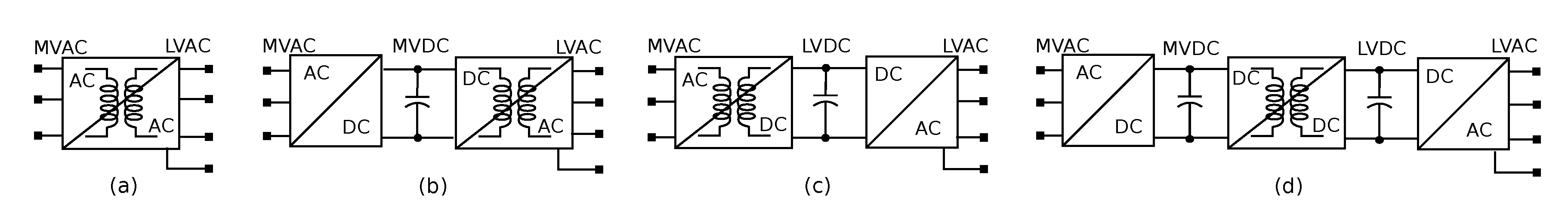
Figure 2.
Single input single output (SISO) building blocks for formation of SST: (a–d) isolated power conversion stage, named ; (e–h) non-isolated power conversion stages, named .
Figure 2.
Single input single output (SISO) building blocks for formation of SST: (a–d) isolated power conversion stage, named ; (e–h) non-isolated power conversion stages, named .
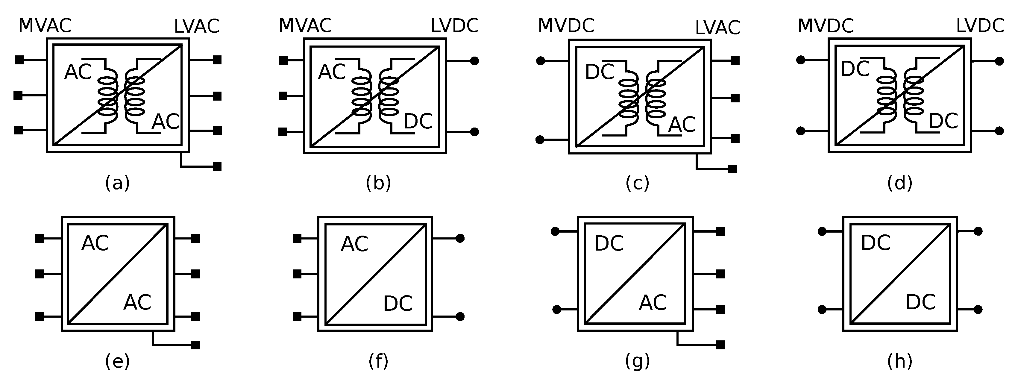
Figure 3.
SST topologies excluded from the existing SST terminology: (a) SPDS AC‖AC/DC SST [16] and (b) SPTS AC‖DC/DC/AC SST [38].

Figure 4.
MIMO building blocks for formation of SST [20,39]: (a) MIMO SPSS AC‖AC SST, (b) MIMO SPSS AC‖DC SST, (c) MIMO SPSS DC‖AC SST, (d) MIMO SPSS DC‖DC SST, and (e) Hybrid-port MIMO SPSS AC‖AC-DC SST.
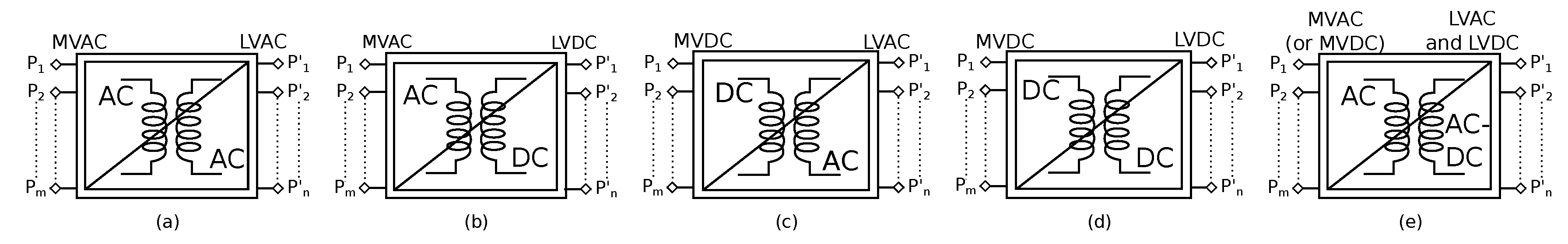
Figure 5.
Different levels of integration for composition of an SST.

Figure 6.
Topological equivalent of at module-level: (a) Half bridge phase leg [40], (b) Matrix converter phase leg [41], (c) Matrix converter phase leg using reversed blocking-IGBT [41], (d) Neutral point clamped converter phase leg [42,43], (e) Flying capacitor phase leg [44], (f) Cascaded H-bridge phase leg [45,46], and (g) Modular multilevel converter phase leg [47].

Figure 7.
Converter level integration [48,49,50]: (a) single , (b) multiple with ISOS interconnection, (c) multiple with ISOP interconnection, (d) multiple with IPOP interconnection, (e) topological equivalent of and (f) topological equivalent of .

Figure 8.
MFT configurations used in SST: (a) single phase transformer [4], (b) three phase transformer [49], (c) single phase multi-winding transformer [55], (d) three phase multi-winding transformer [56], (e) split winding transformer [57], and (f) scott transformer [16].
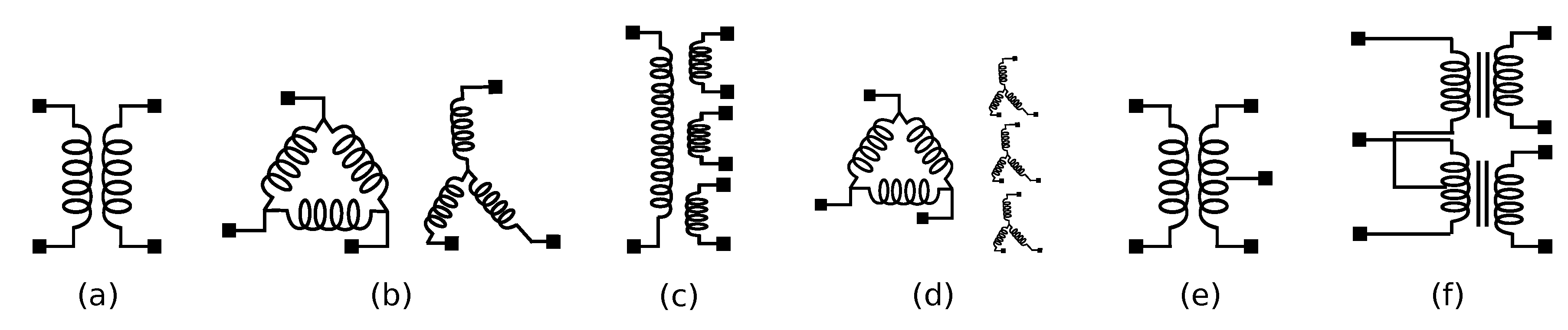
Figure 9.
Different types of [32]: (a) formed using single phase transformer and single , (b) formed using single phase transformer and multiple , (c) for multi-winding transformer, (d) using three phase transformer and three phase , and (e) formed using a three phase transformer and multiple single phase .
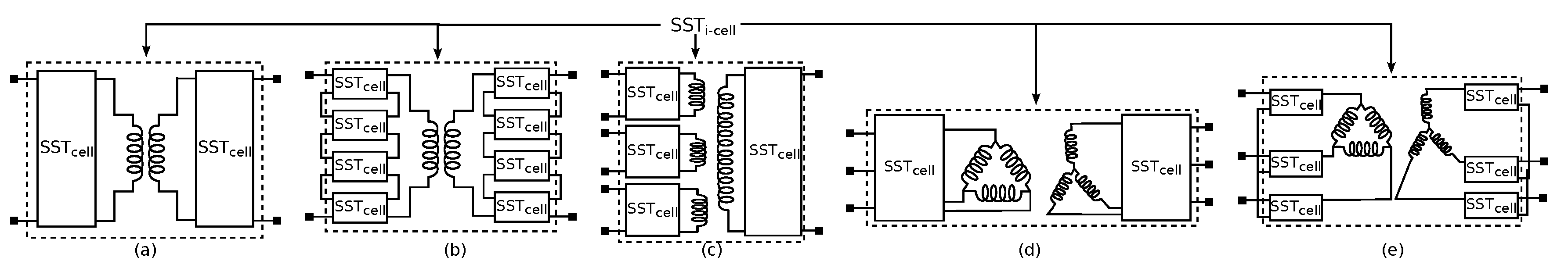
Figure 10.
Stage extension at cell level and formation of using multi-stage [54,58]: (a) two-stage , (b) two-stage , (c) three-stage , (d) two-stage in ISOP configuration, and (e) three-stage in ISOS configuration.
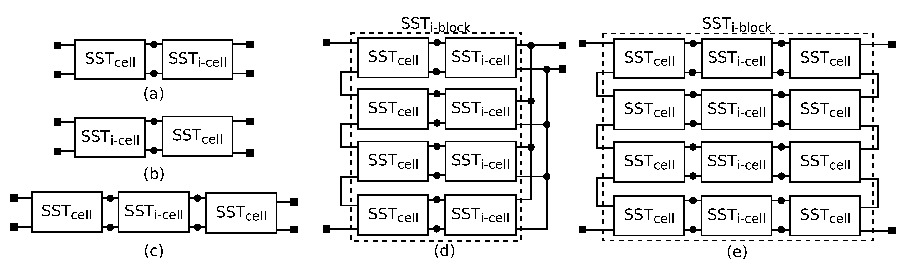
Figure 11.
Formation of MIMO [58]: (a) MIMO: three port using , (b) MIMO: three port SST using two stage , (c) MIMO: hybrid-port .
Figure 11.
Formation of MIMO [58]: (a) MIMO: three port using , (b) MIMO: three port SST using two stage , (c) MIMO: hybrid-port .

Figure 12.
Classification of SSTs.

Figure 13.
Classification of SST based on voltage levels: (a) MV/LV configuration [48,49]; (b) HV/MV configuration [59,60].
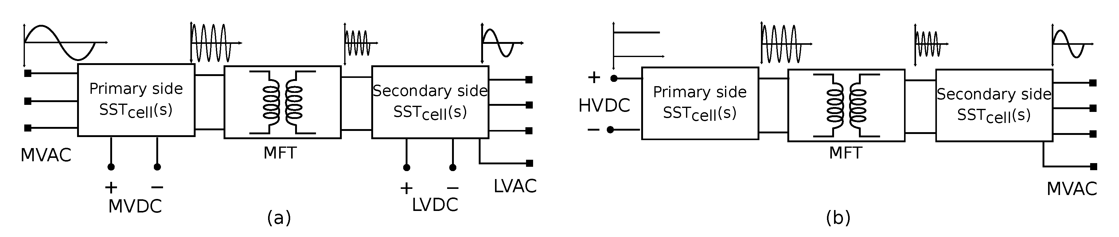
Figure 14.
Coupled control: isolation stage () based on non-resonant stages: (a) dual active bridge [69,76] (b) AC/AC DAB for SST [72], (c) isolated AC/AC dyna C [74], (d) multiple active bridge (MAB): quad active bridge (QAB) [76].
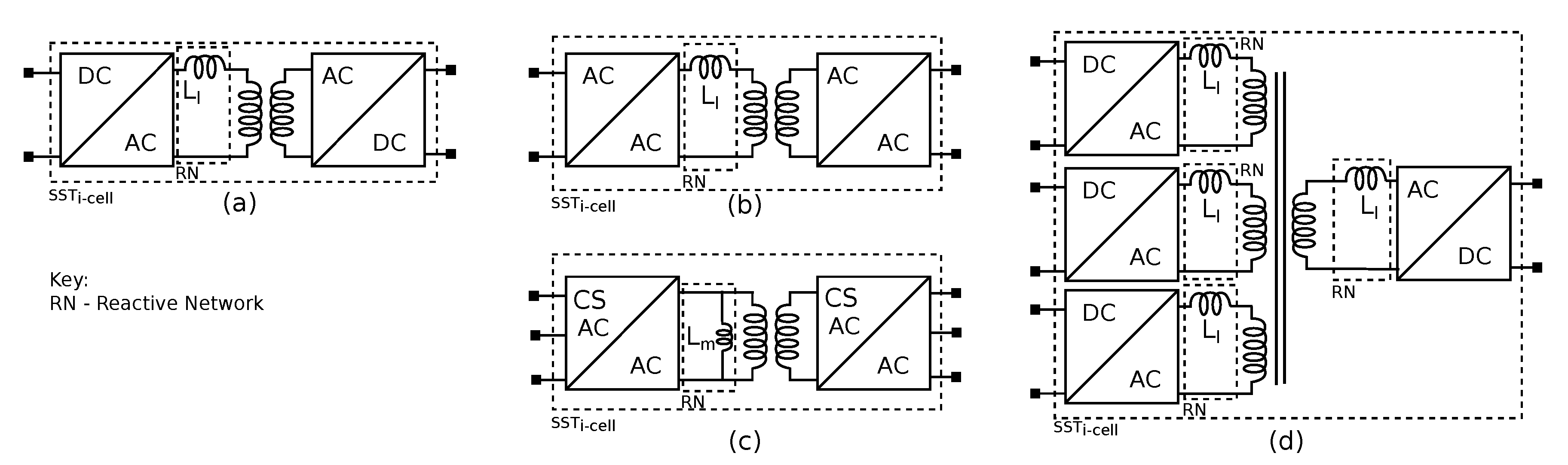
Figure 15.
Coupled control: isolation stage based on resonance stage [38,68,79]: (a) isolated DC/DC stage based on series resonance circuit, (b) isolated DC/DC stage based on parallel resonance circuit, (c) isolated DC/DC stage based on hybrid LLC resonance circuit, (d) isolated DC/DC stage based on hybrid LCC resonance circuit, (e) isolated AC/DC stage based on LLC circuit.
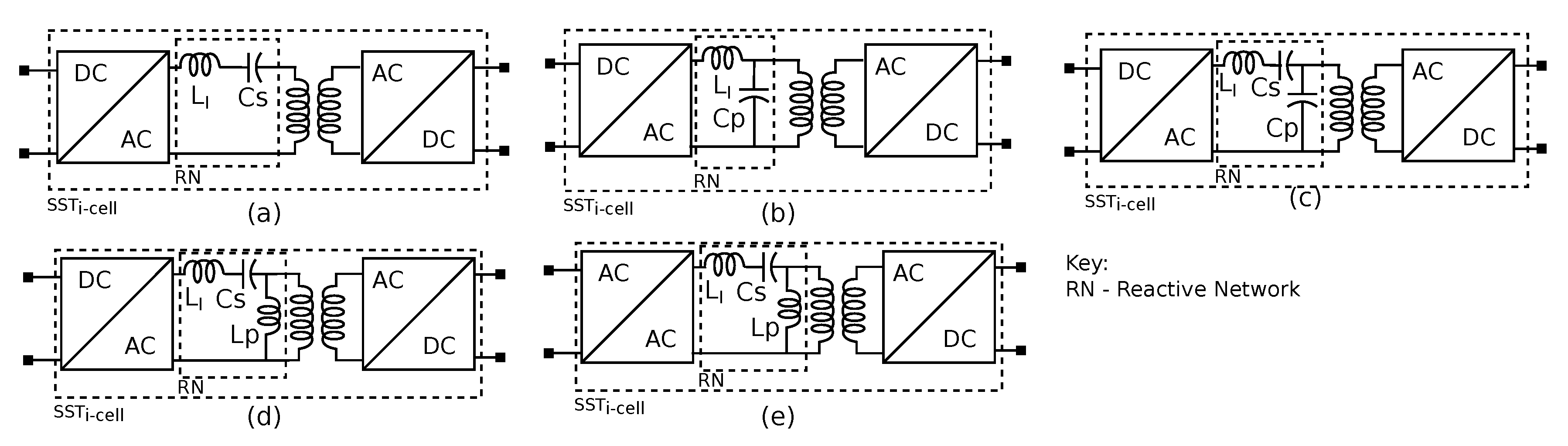
Figure 16.
Modularization in the direction of power flow: (a) non-modular or single stage SSTs, (b) two-stage SSTs, and (c) three stage SSTs.
Figure 16.
Modularization in the direction of power flow: (a) non-modular or single stage SSTs, (b) two-stage SSTs, and (c) three stage SSTs.

Figure 17.
Modularization based on voltage/current levels: (a) non-modular SSTs, (b) hybrid-cell SPDS SSTs, and (c) fully modular multi-cell SSTs.
Figure 17.
Modularization based on voltage/current levels: (a) non-modular SSTs, (b) hybrid-cell SPDS SSTs, and (c) fully modular multi-cell SSTs.

Figure 18.
Modularization based on phase interconnection: (a) non-modular SSTs, (b) semi-phase modular SSTs, and (c) fully phase modular SSTs.
Figure 18.
Modularization based on phase interconnection: (a) non-modular SSTs, (b) semi-phase modular SSTs, and (c) fully phase modular SSTs.


Figure 20.
Modularity in voltage interconnection: (a) single stage cells fully modular [91], (b) two stage cells fully modular [58], and (c) hybrid-cell modular SST [10].

Figure 21.
Fully phase modular SST as presented in [54].
Figure 21.
Fully phase modular SST as presented in [54].
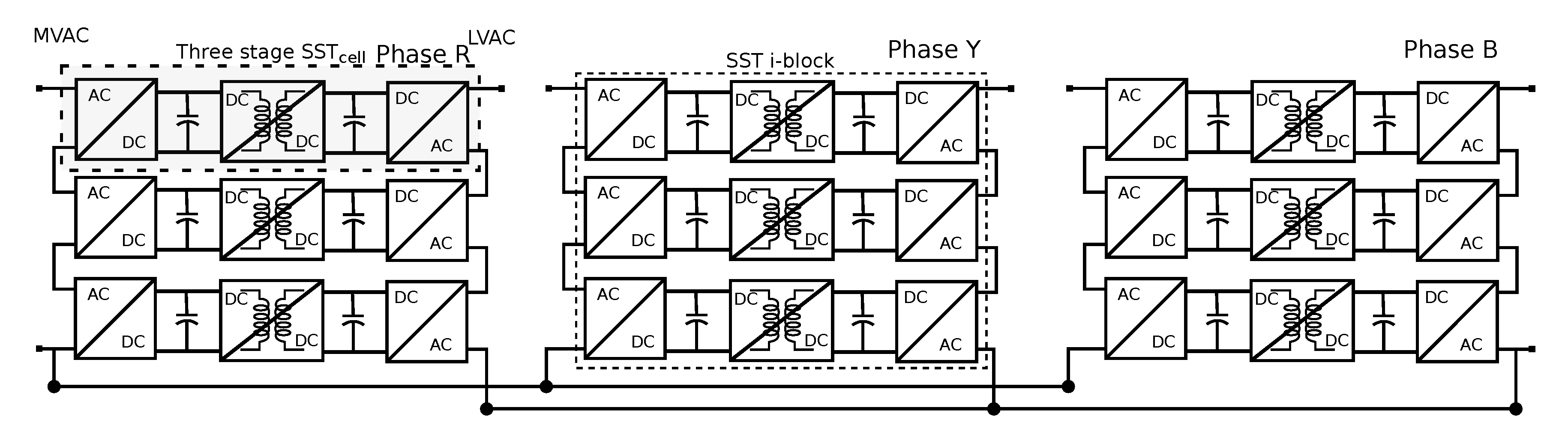
Figure 22.
Phase modular SSTs presented in [19,55,77,94]: (a) using front end MMC and back end DAB in ISOP, (b) CHB with DAB in ISOP configuration, (c) QAB in ISOP configuration, and (d) interphase QAB in ISOP configuration.
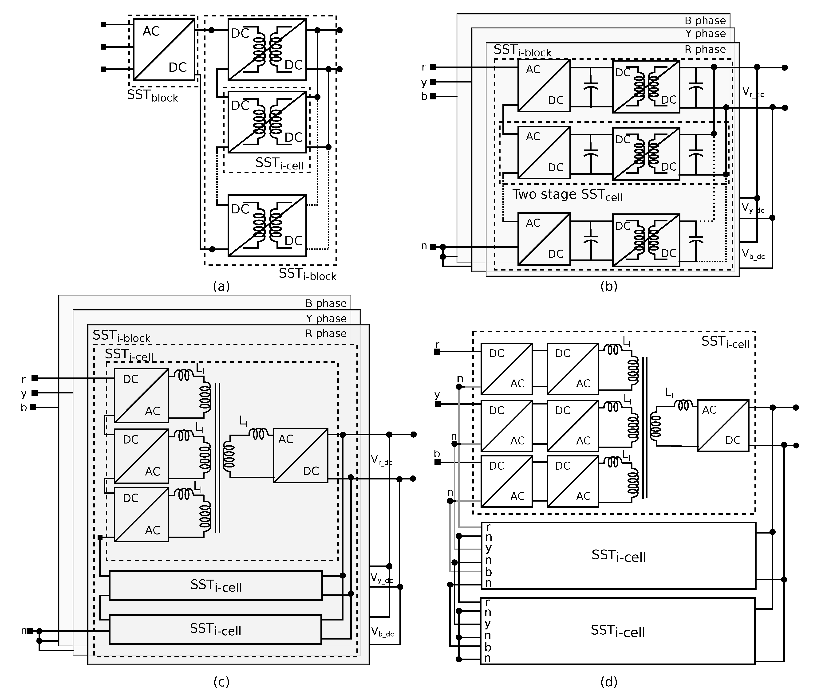
Figure 23.
Transformer core geometries [130,140,141]: (a) core type, (b) shell type, (c) matrix type, and (d) CWT.

Figure 24.
Application of SST in wind turbines as highlighted in [160].
Figure 24.
Application of SST in wind turbines as highlighted in [160].

Figure 25.
Application of SST in traction as illustrated in [58].
Figure 25.
Application of SST in traction as illustrated in [58].

Figure 26.
Application of SST for Grid interfacing as demonstrated in [39].
Figure 26.
Application of SST for Grid interfacing as demonstrated in [39].

Figure 27.
Grid interfacing with MPC as presented in [161].
Figure 27.
Grid interfacing with MPC as presented in [161].


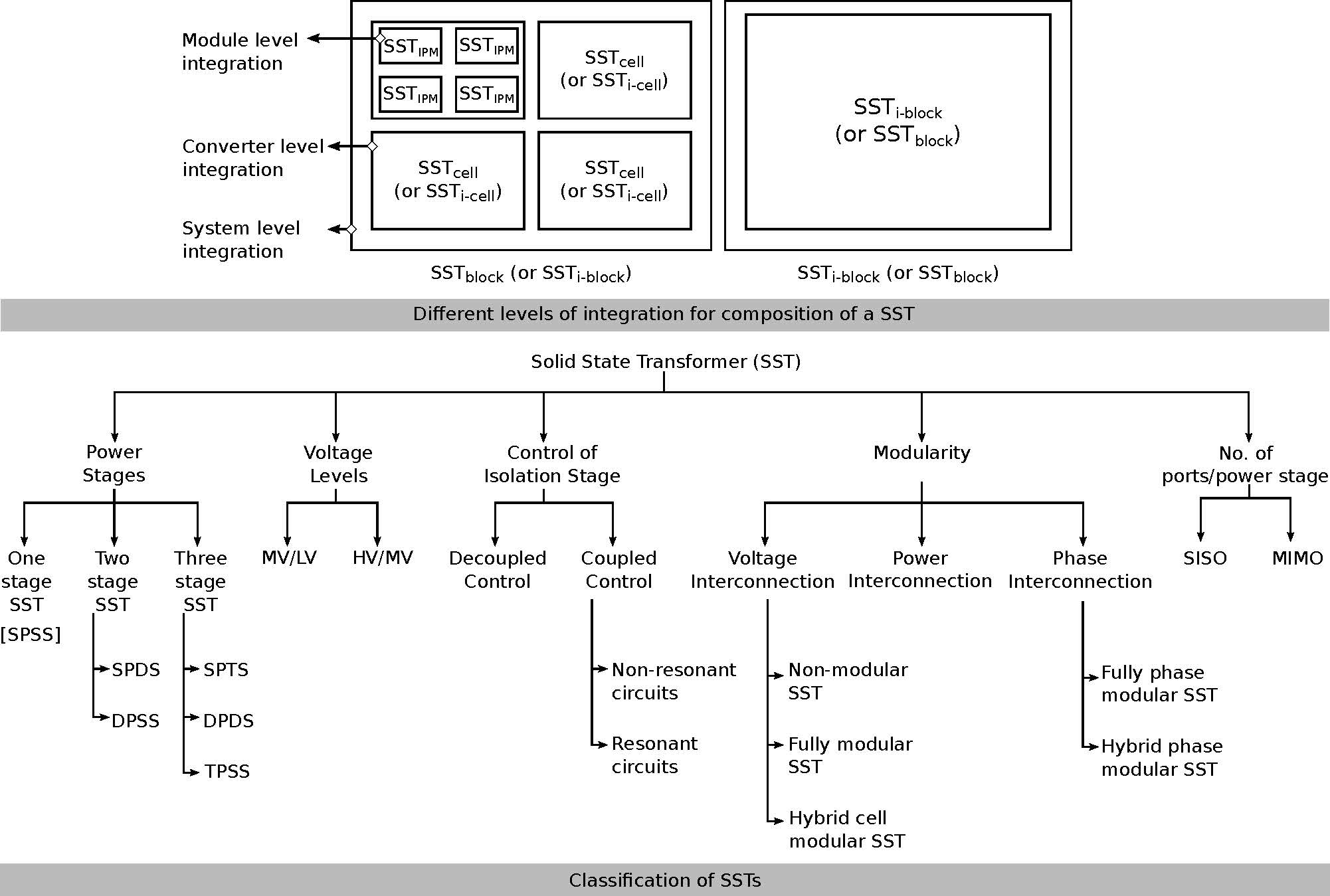
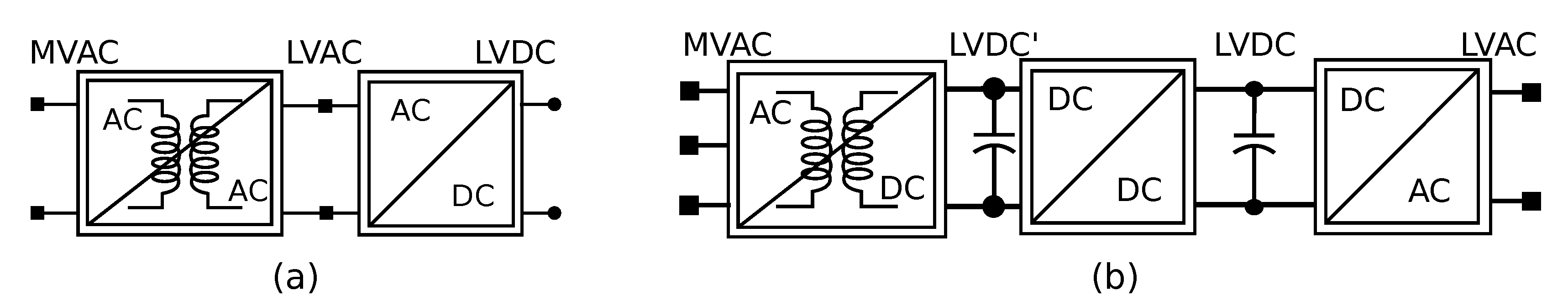
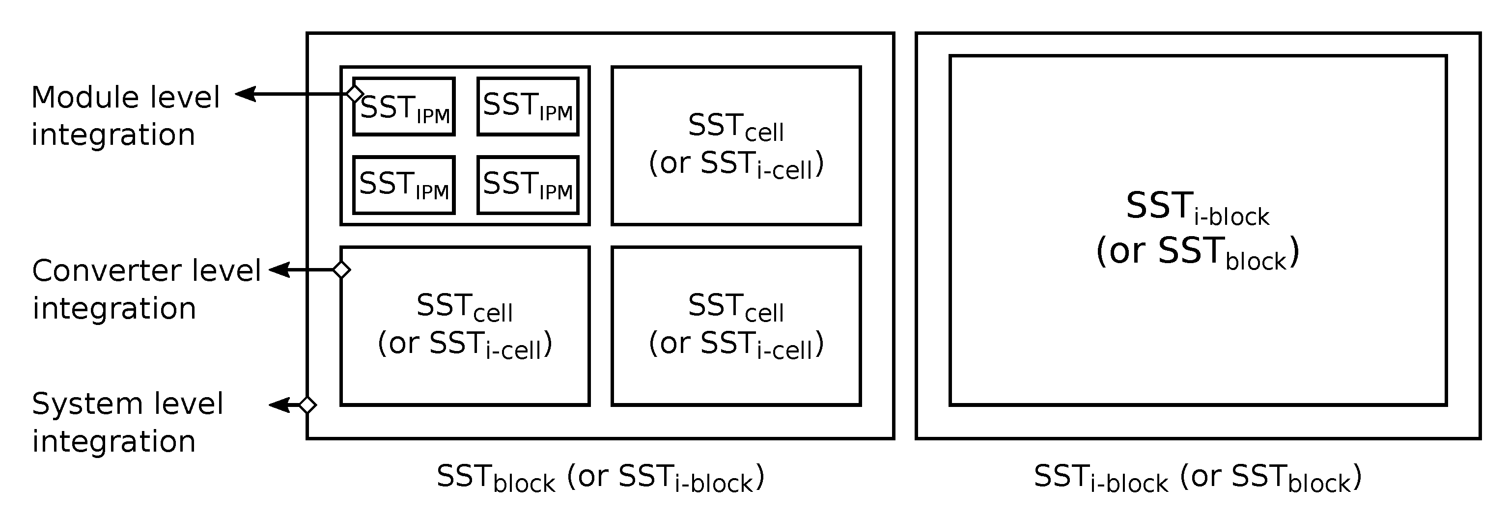
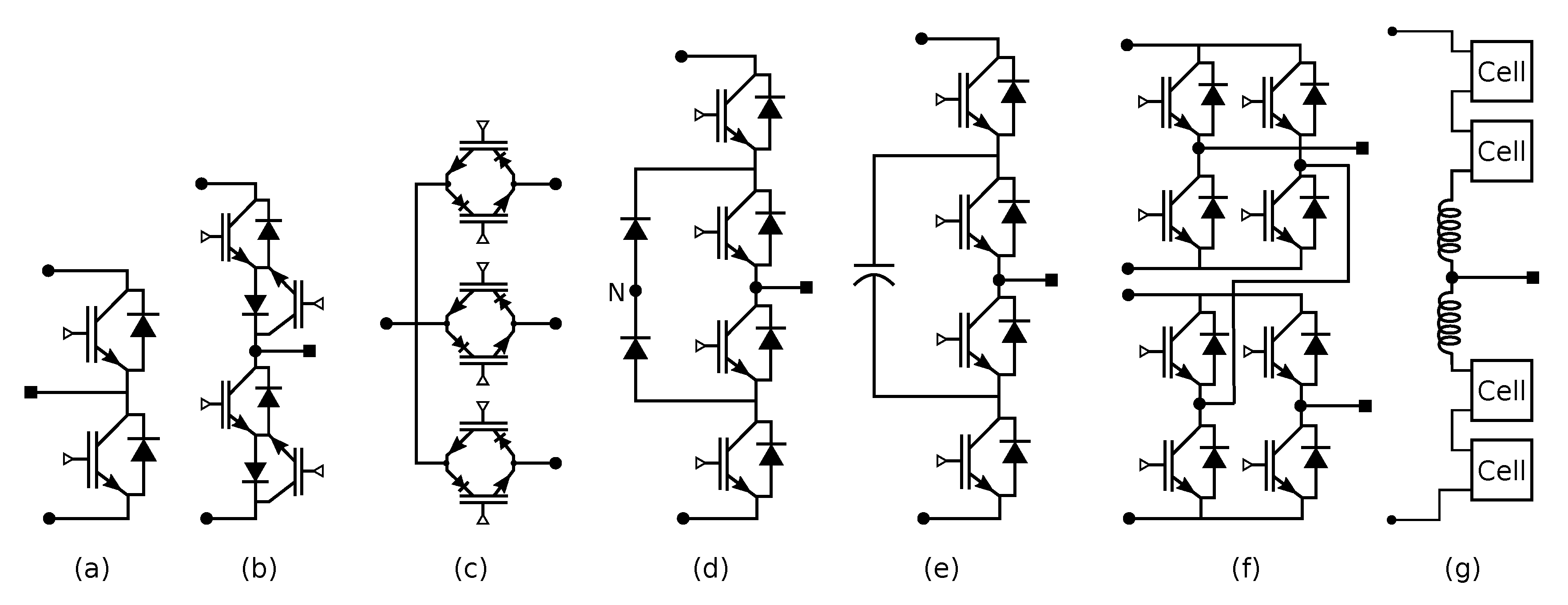
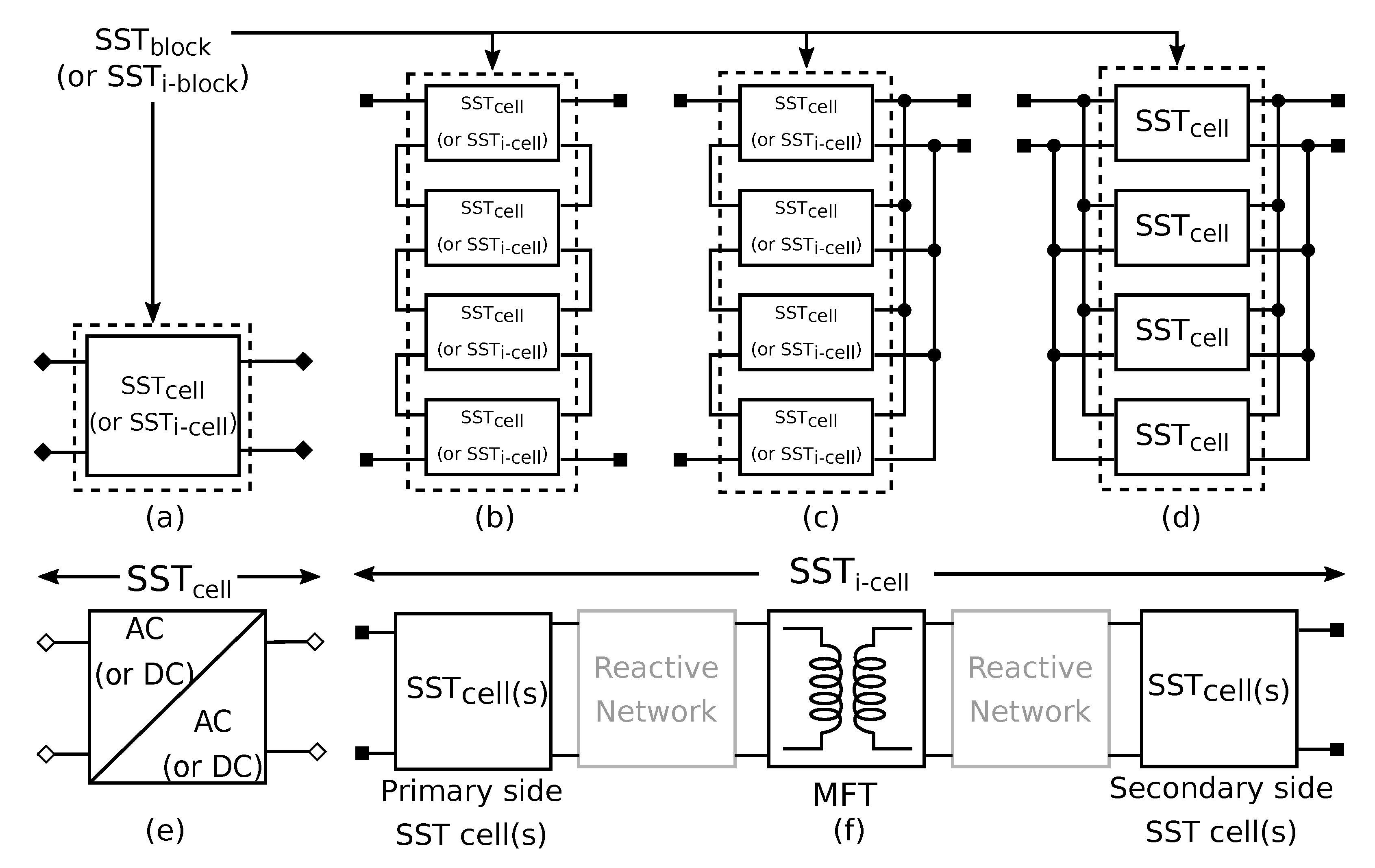
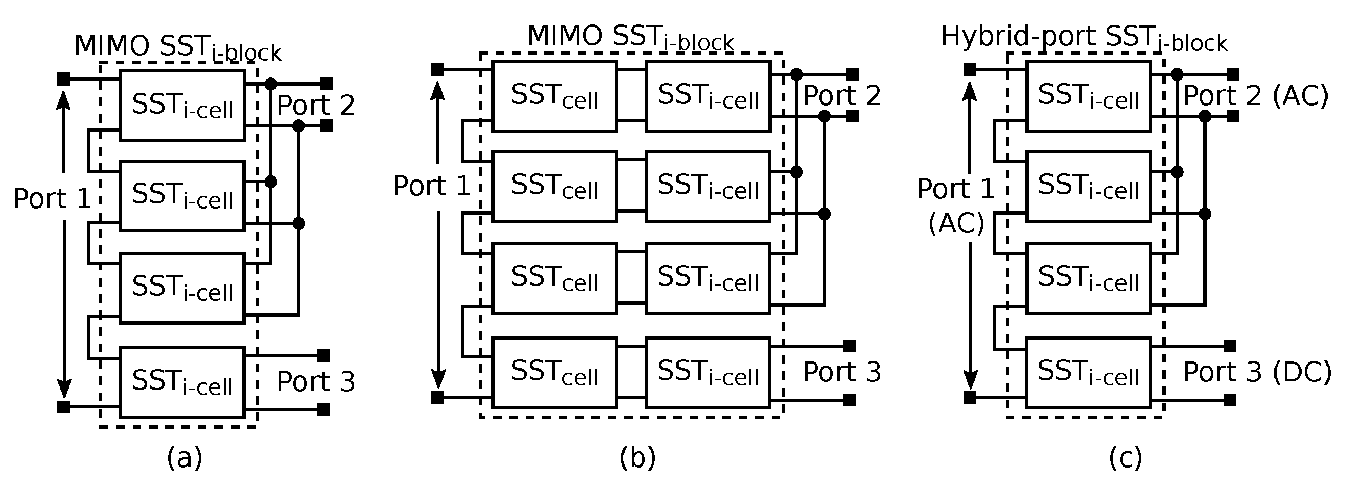
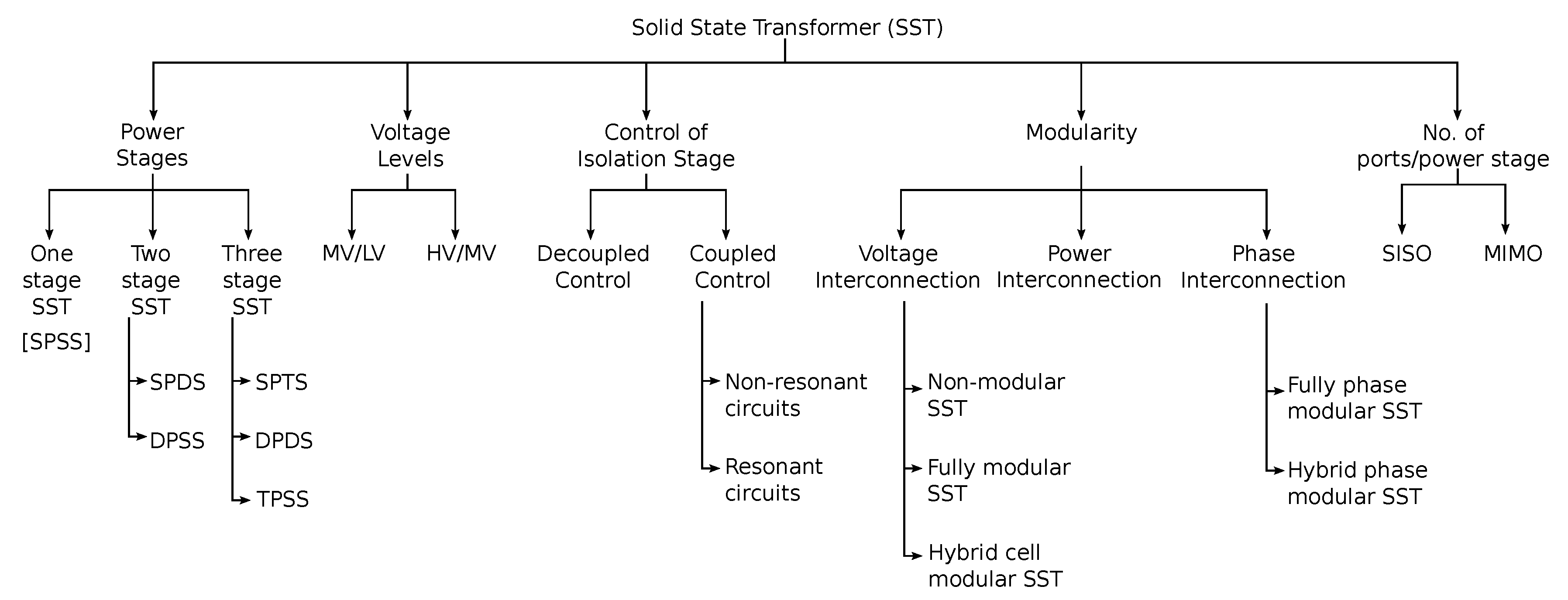
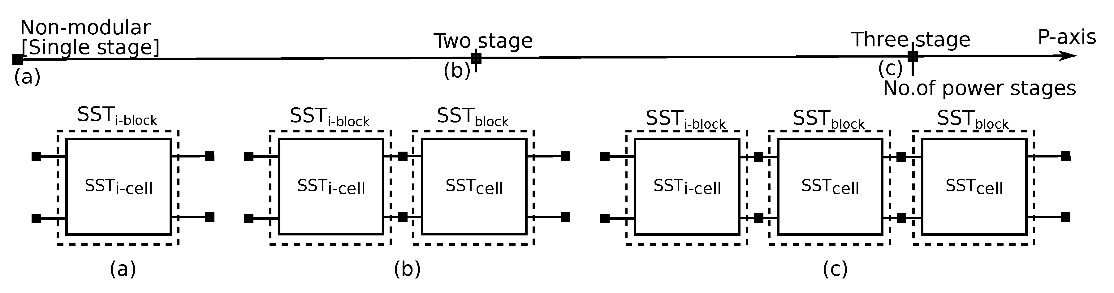
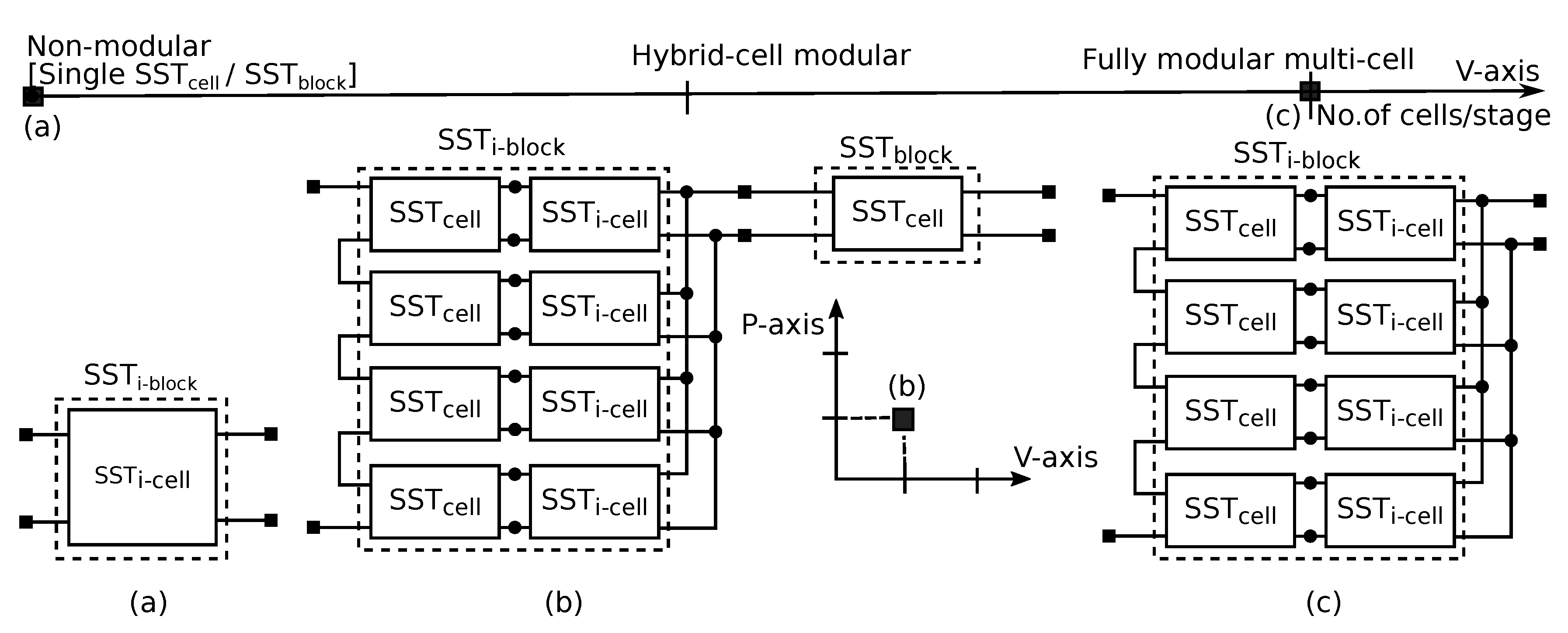
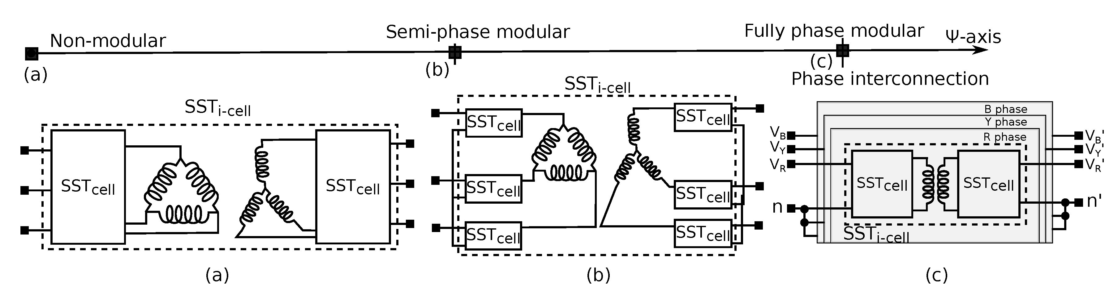
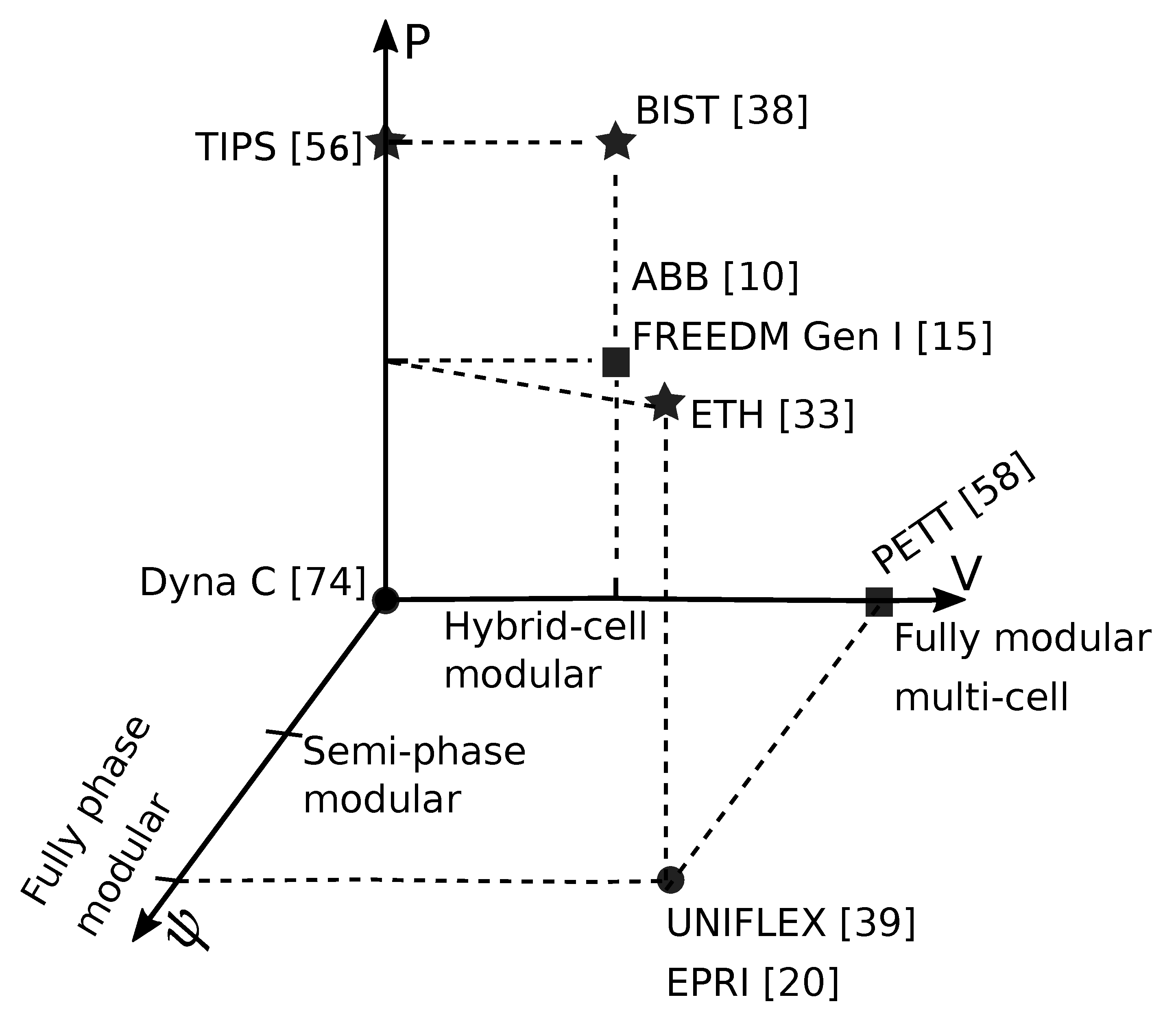
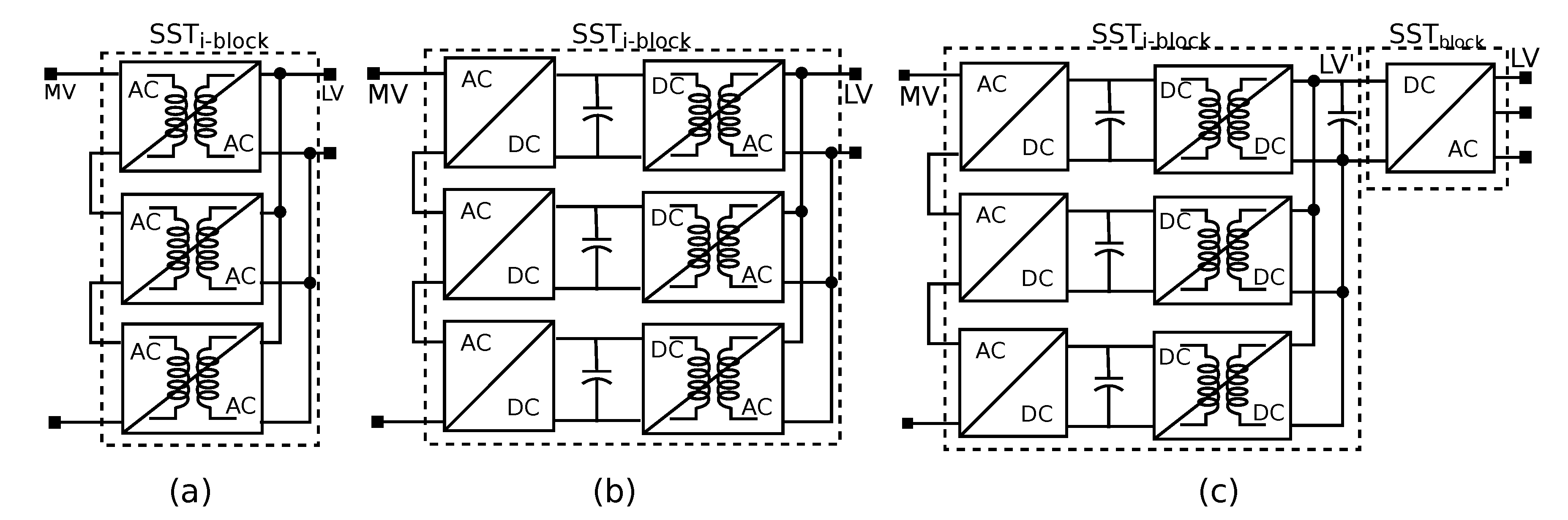
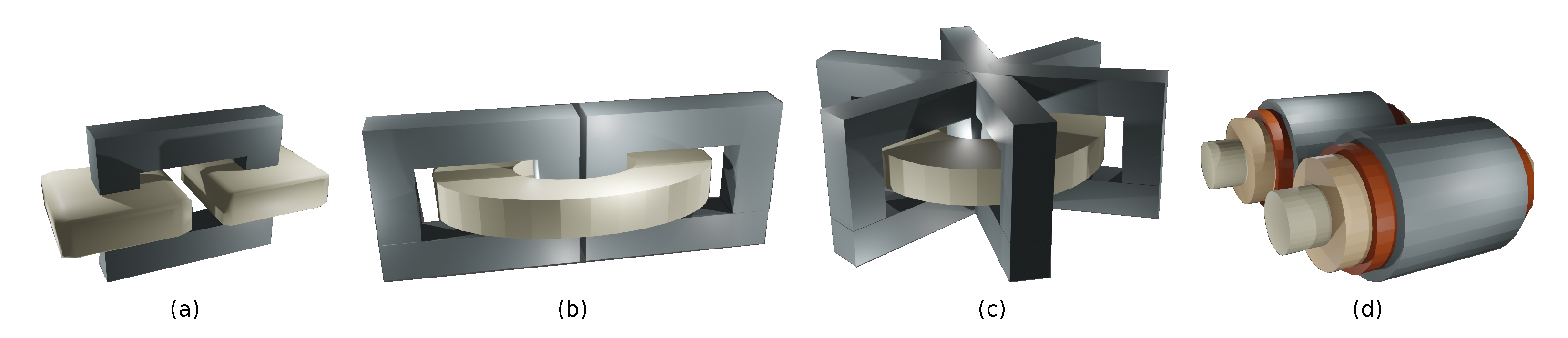
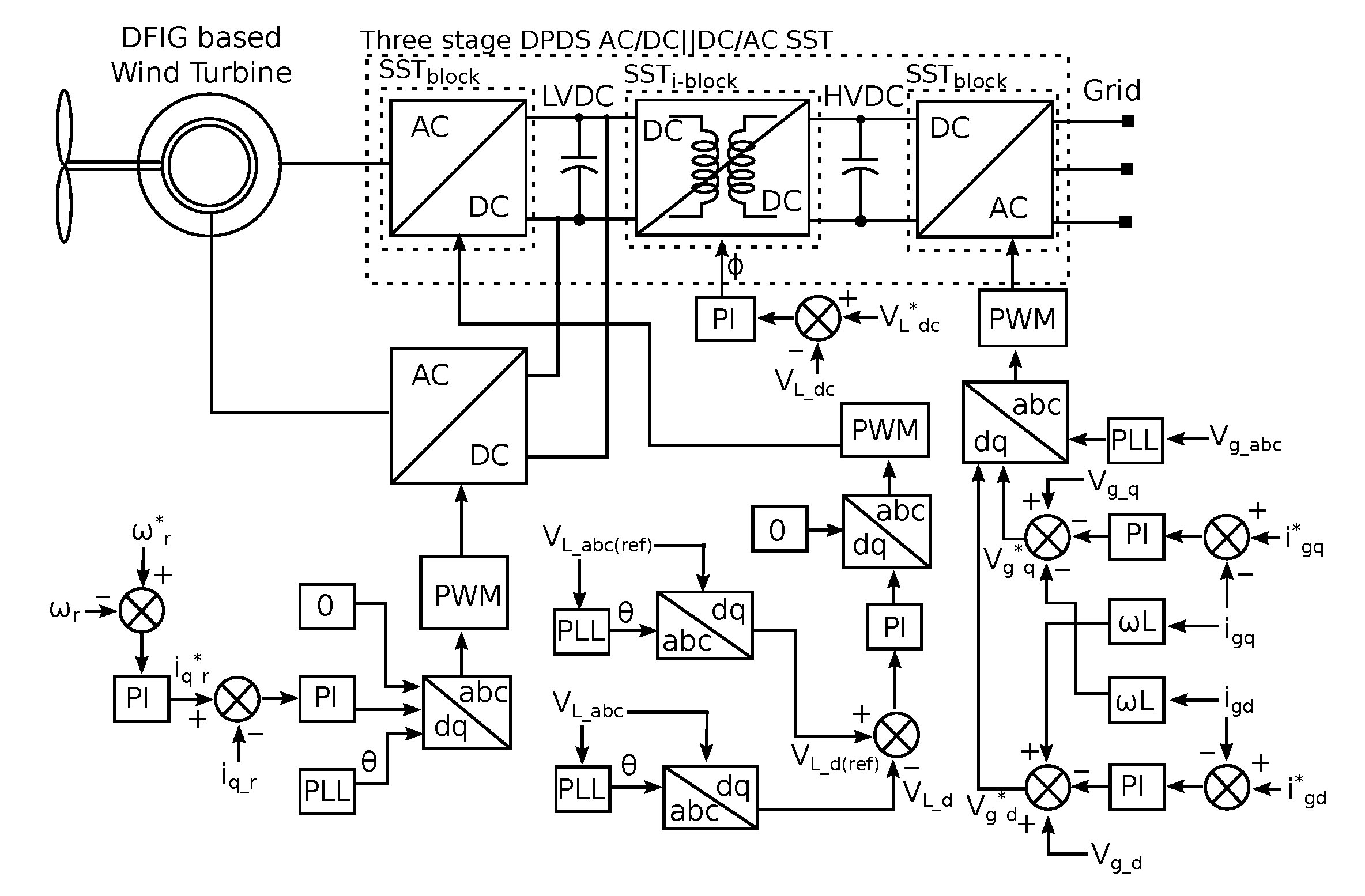
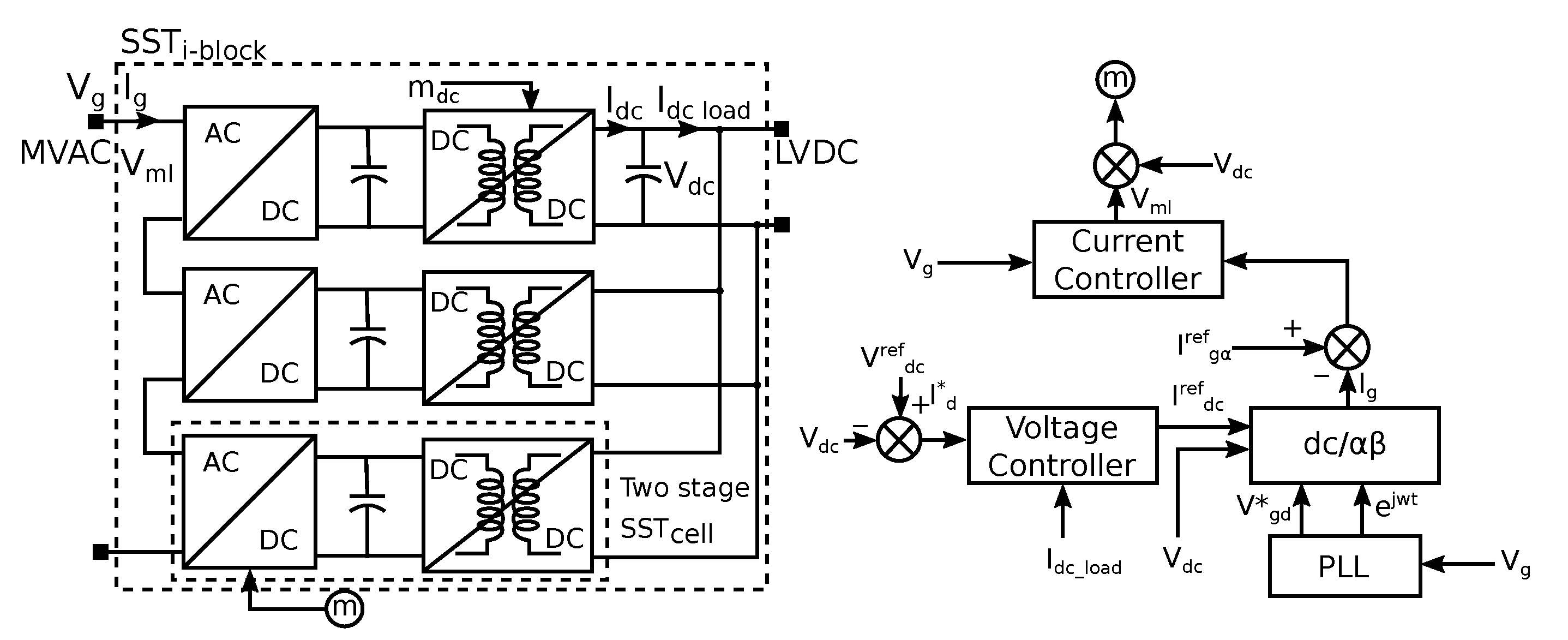
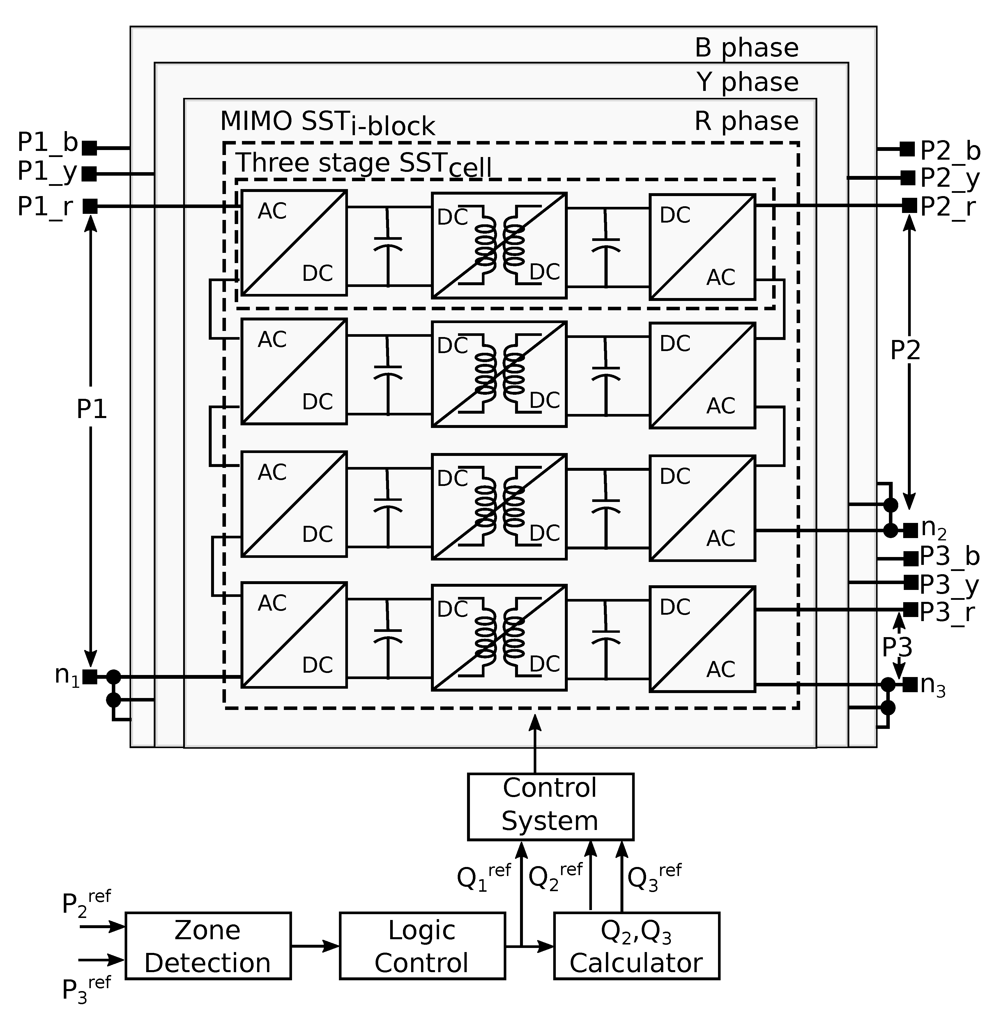
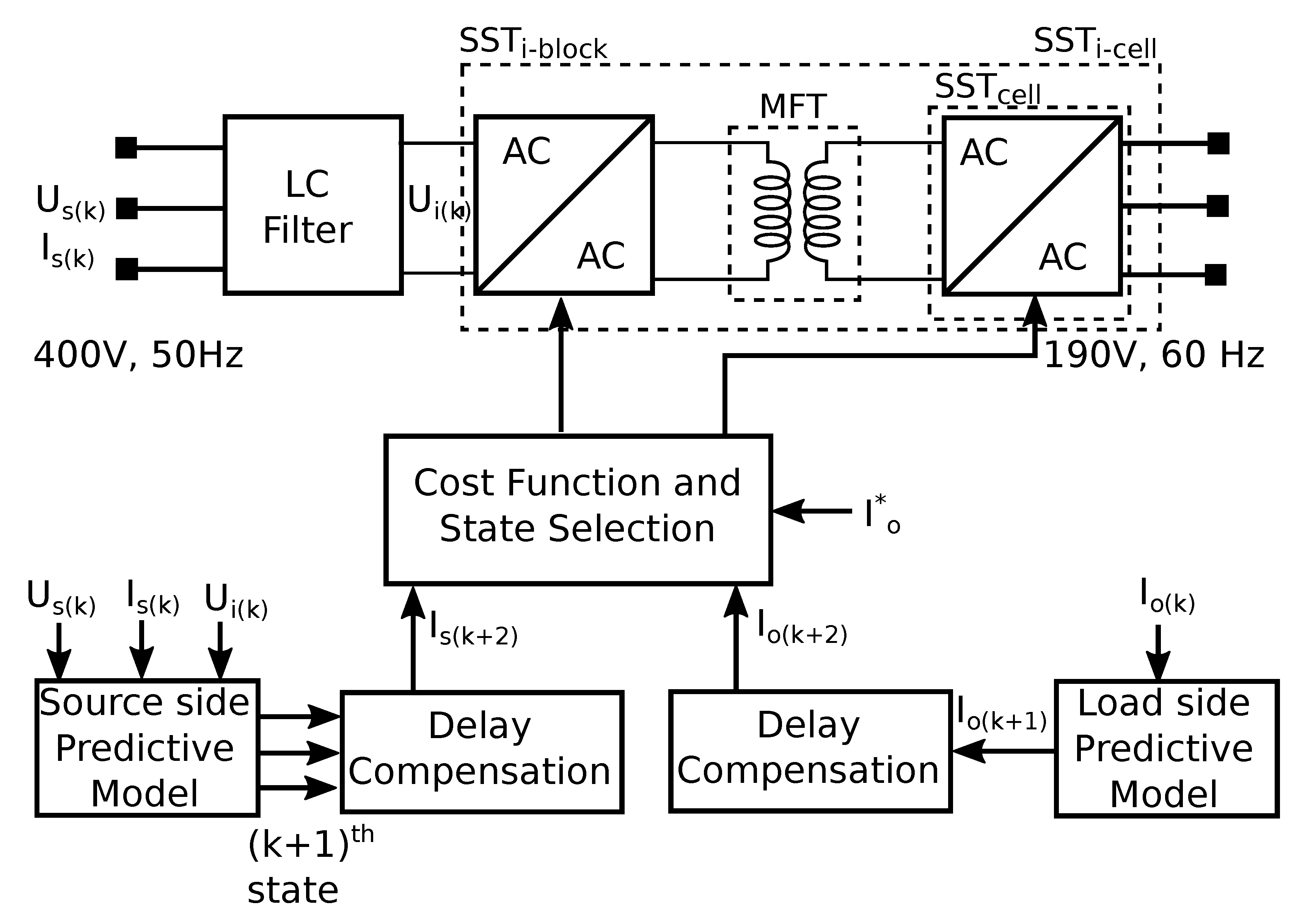
| Low | Medium | High | Standard | |
|---|---|---|---|---|
| AC power systems | 100 V–1 kV | 1 kV–35 kV | 35 kV–230 kV | |
| DC traction systems | 500 V–900 V | 1 kV–3.6 kV | - | IEC 60038 |
| DC power systems | - | 12 kV–27.5 kV | - | |
| Distribution systems | - | 1 kV–66 kV | - | German: BDEW 2008 |
| AC voltage levels | EVA LVA LVB | - | HVA: (1 kV–50 kV) HVB: (>50 kV) | French Decree 2008 No. 88–1056 |
Table 2.
Properties of selected soft magnetic materials [30].
Table 2.
Properties of selected soft magnetic materials [30].
| Material | Alloy Composition in % | Losses in [W/kg] at (20 kHz, 200 mT) | Bsat in Tesla | at (50 Hz) | Max Working Temp [CC] | |
|---|---|---|---|---|---|---|
| Grain Oriented Silicon Steel | Fe97Si3 | >1000 | 2 | 9 | 2000–35,000 | ∼120 |
| Standard crystalline permalloy I | Ni45Fe55 | >150 | 1.55 | 25 | 12,000–80,000 | 130 |
| Standard crystalline permalloy II | Ni45Fe55 | >100 | 1.5 | 25 | 60,000–125,000 | 130 |
| Advanced Silicon steel | Fe93.5 Si6.5 | 40 | 1.3 | 0.1 | 16,000 | 130 |
| Fe- amorphous alloy | Fe76(Si,B)24 | 18 | 1.56 | 27 | 6500–8000 | 150 |
| High performance ferrite | MnZn | 17 | 0.5 | 21 | 1500–15,000 | 100/120 |
| Advanced crystalline permalloy | Ni80Fe20 | >15 | 0.8 | 1 | 150,000–300,000 | 130 |
| Co-amorphous alloys a | Co73(Si,B)27 | 5 | 0.55 | <0.2 | 100,000–150,000 | 90/120 |
| Co-amorphous alloys b | Co77(Si,B)23 | 5.5 | 0.82 | <0.2 | 2000–4500 | 120 |
| Co-amorphous alloys c | Co80(Si,B)20 | 6.5 | 1 | <0.2 | 1000–2500 | 120 |
| Nanocrystalline alloys I | FeCuNbSiB | 4 | 1.23 | 0.1 | 20,000–200,000 | 120/180 |
| Nanocrystalline alloys II | FeCuNbSiB | 4.5 | 1.35 | 2.3 | 20,000–200,000 | 120/180 |
| Nanocrystalline alloys III | FeCuNbSiB | 8 | 1.45 | 5.5 | ∼100,000 | 120/180 |
Table 3.
Properties of insulation materials reported in [153].
Table 3.
Properties of insulation materials reported in [153].
| Material | Continuous | Dielectric | Dielectric | Thermal |
|---|---|---|---|---|
| Temperature (°C) | Strength | Constant | Conductivity (W/mK) | |
| Mylar | 105 | 10.0 kVAC (3 mil) | 3.30 | 0.37 @ 50 °C |
| Tedlar | 107 | 4.2 kVAC (2 mil) | 11.0 | 0.35 @ 50 °C |
| Nomex | 220 | 1.6 kVAC (3 mil) | 1.6 | 0.11 @ 50 °C |
| Kapton | 400 | 13.8 kVAC (3 mil) | 3.70 | 0.18 @ 50 °C |
| Epoxy Powder Coating | 130 | 10.0 kVAC (10 mil) | 4.00 | 0.60 @ 50 °C |
© 2020 by the authors. Licensee MDPI, Basel, Switzerland. This article is an open access article distributed under the terms and conditions of the Creative Commons Attribution (CC BY) license (http://creativecommons.org/licenses/by/4.0/).
Share and Cite
MDPI and ACS Style
Shamshuddin, M.A.; Rojas, F.; Cardenas, R.; Pereda, J.; Diaz, M.; Kennel, R. Solid State Transformers: Concepts, Classification, and Control. Energies 2020, 13, 2319. https://doi.org/10.3390/en13092319
AMA Style
Shamshuddin MA, Rojas F, Cardenas R, Pereda J, Diaz M, Kennel R. Solid State Transformers: Concepts, Classification, and Control. Energies. 2020; 13(9):2319. https://doi.org/10.3390/en13092319
Chicago/Turabian StyleShamshuddin, Mohammed Azharuddin, Felix Rojas, Roberto Cardenas, Javier Pereda, Matias Diaz, and Ralph Kennel. 2020. "Solid State Transformers: Concepts, Classification, and Control" Energies 13, no. 9: 2319. https://doi.org/10.3390/en13092319
Note that from the first issue of 2016, this journal uses article numbers instead of page numbers. See further details here.