

Overcoming Scaling Challenges in Sol–Gel Synthesis: A Microwave-Assisted Approach for Iron-Based Energy Materials


Abstract

1. Introduction
2. Materials and Methods
3. Results and Discussion
3.1. Scaling-Up Iron Aerogels by Multimode Microwave Heating
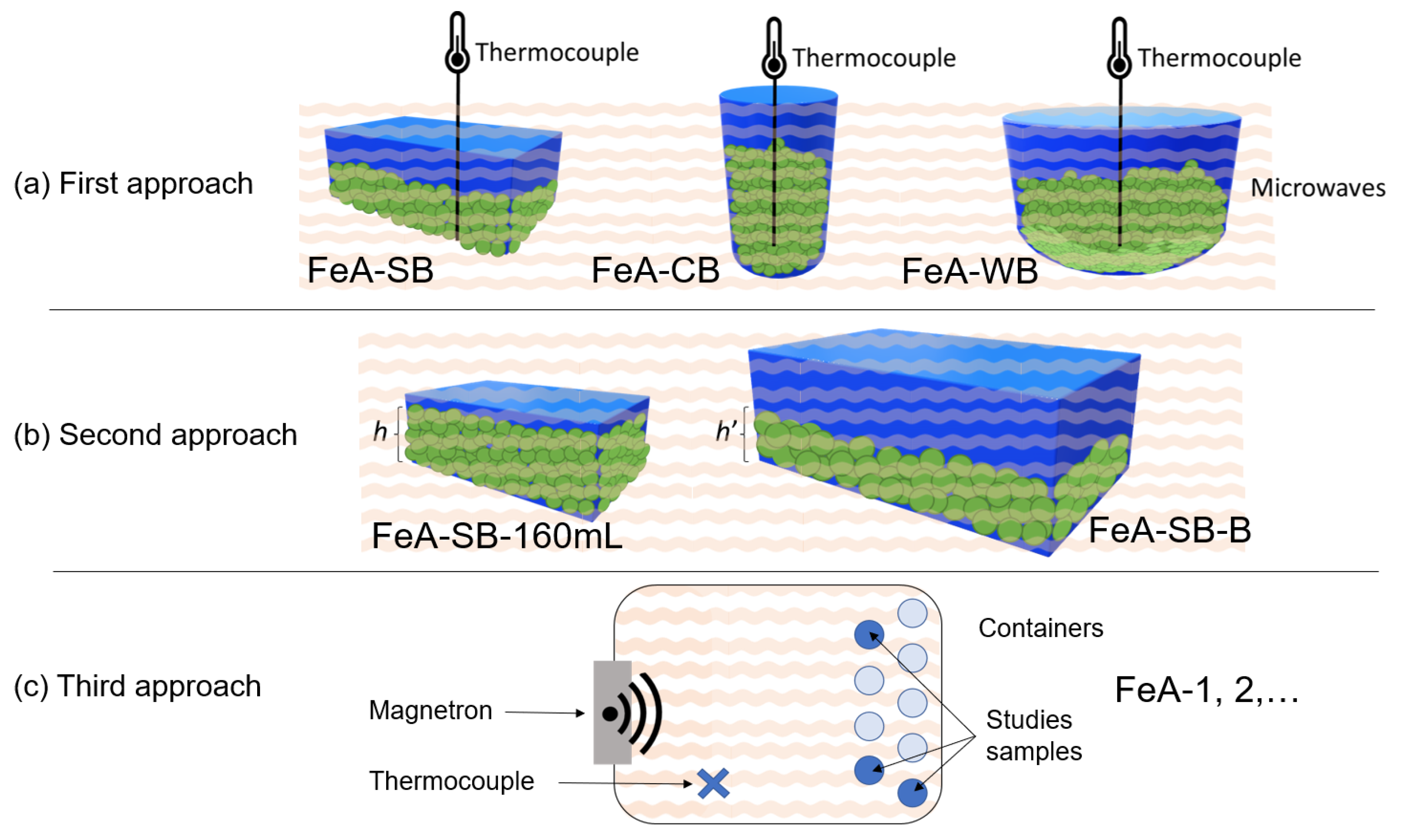
3.1.1. First Aspect to Consider: Shape of the Vessel
3.1.2. Second Approach: Volume of the Vessel
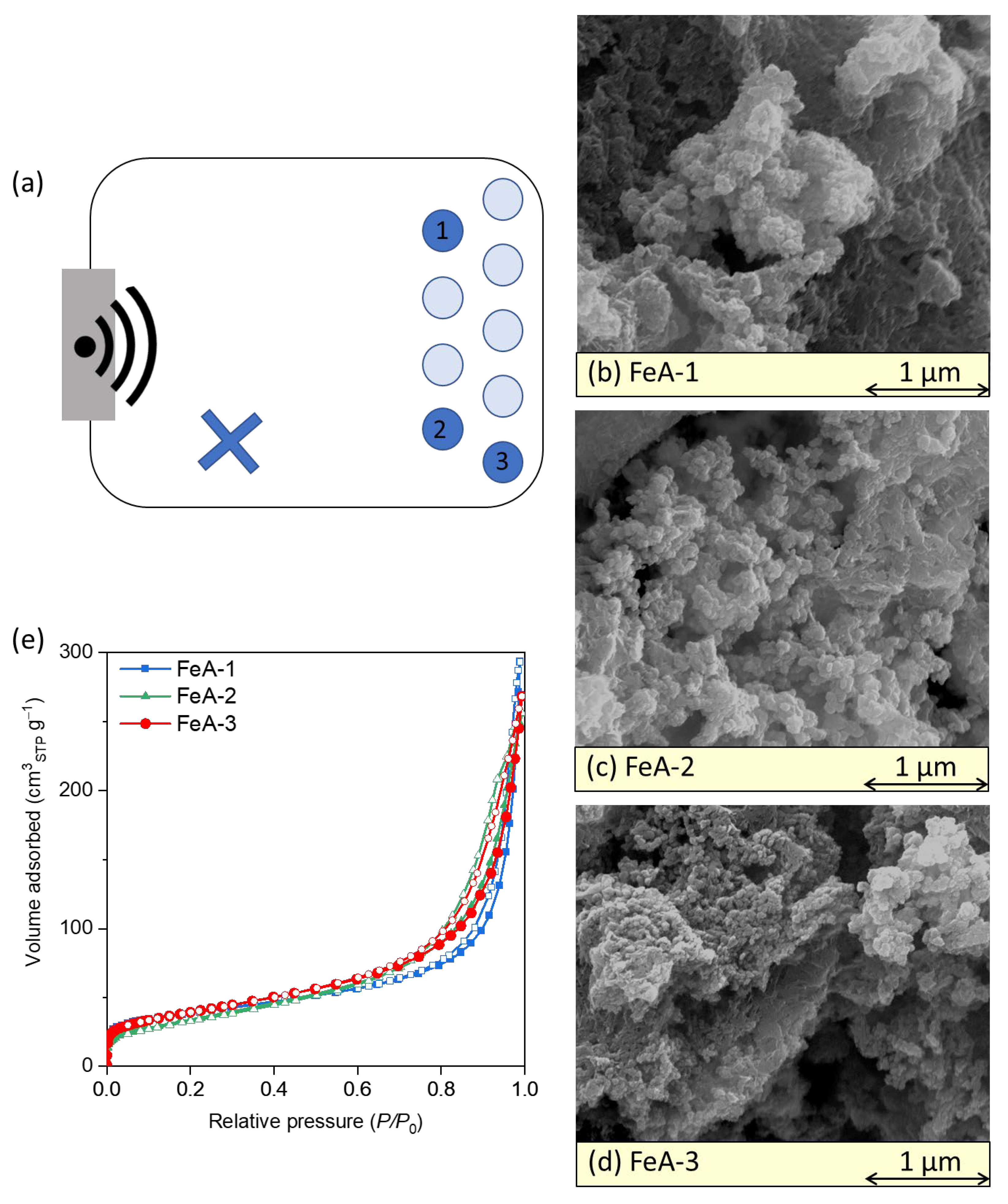
3.1.3. Third Approach: Replicating Small Volumes
4. Conclusions
Supplementary Materials
Author Contributions
Funding
Institutional Review Board Statement
Informed Consent Statement
Data Availability Statement
Conflicts of Interest
Abbreviation
| TMA | Transition metal aerogel |
| FeA | Iron aerogel |
| FeA-SB | Iron aerogel synthesized in a square-based vessel of 250 mL with 80 mL of precursor solution |
| FeA-CB | Iron aerogel synthetized in a circular-based vessel |
| FeA-WB | Iron aerogel synthetized in a wide circular-based vessel |
| FeA-SB-160mL | Iron aerogel synthetized in a square-based vessel of 250 mL with 160 mL of precursor solution |
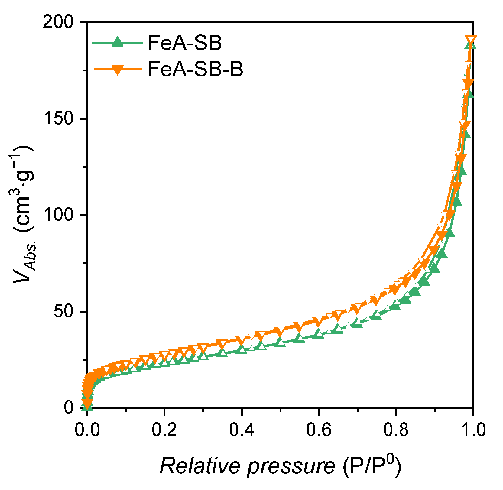
| FeA-SB-B | Iron aerogel synthetized in a square-based vessel of 500 mL with 160 mL of precursor solution |
| FeA-1 FeA-2 FeA-3 | Iron aerogels synthetized in circular vessels of 100 mL with 80 mL of precursor solution situated at different positions inside the microwave cavity |
| TE | Transverse Electric mode |
| TM | Transverse Magnetic mode |
References
- González-Lavín, J.; Martínez Lázaro, A.; Rodríguez-Barajas, M.; Ledesma, J.; Arriaga, L.; Arenillas, A.; Rey-Raap, N. Metallic Aerogels for Their Use in Sustainable Energy Generation. In Electrochemical Methods for the Synthesis and Analysis of Advanced Functional Layers and Coatings; Kozhukharov, S.V., Ed.; Cambridge Scholars Publishing: Newcastle upon Tyne, UK, 2024; pp. 1–42. ISBN 9781036410964. [Google Scholar]
- Levy, D.; Zayat, M. The Sol-Gel Handbook; Wiley-VCH Verlag GmbH & Co.: Weinheim, Germany, 2015; pp. 1–1508. [Google Scholar] [CrossRef]
- Bokov, D.; Turki Jalil, A.; Chupradit, S.; Suksatan, W.; Javed Ansari, M.; Shewael, I.H.; Valiev, G.H.; Kianfar, E. Nanomaterial by Sol-Gel Method: Synthesis and Application. Adv. Mater. Sci. Eng. 2021, 5102014. [Google Scholar] [CrossRef]
- Esposito, S. Sol-Gel Synthesis Strategies for Tailored Catalytic Materials; Bhatia, S., Diebold, A., Hu, J., Krishnan, K., Narducci, D., Ray, S.S., Wilde, G., Eds.; Springer Briefs in Materials; Springer International Publishing: Turin, Italy, 2023; ISBN 978-3-031-20722-8. [Google Scholar]
- Awadallah-F, A.; Al-Muhtaseb, S.A. Utilizing Thermal Energy for Crosslinking Gels: A Novel Rapid Approach. Energies 2023, 16, 1447. [Google Scholar] [CrossRef]
- Oghbaei, M.; Mirzaee, O. Microwave versus Conventional Sintering: A Review of Fundamentals, Advantages and Applications. J. Alloys Compd. 2010, 494, 175–189. [Google Scholar] [CrossRef]
- Sun, J.; Wang, W.; Yue, Q. Review on Microwave-Matter Interaction Fundamentals and Efficient Microwave-Associated Heating Strategies. Materials 2016, 9, 231. [Google Scholar] [CrossRef]
- Stuerga, D. Microwave-Material Interactions and Dielectric Properties, Key Ingredients for Mastery of Chemical Microwave Processes. In Microwaves in Organic Synthesis; Loupy, A., Ed.; Wiley-VCH Verlag GmbH & Co.: Weinheim, Germany, 2006; pp. 1–1007. ISBN 3-527-31452-0. [Google Scholar]
- Stadler, A.; Pichler, S.; Horeis, G.; Kappe, C.O. Microwave-Enhanced Reactions under Open and Closed Vessel Conditions. A Case Study. Tetrahedron 2002, 58, 3177–3183. [Google Scholar] [CrossRef]
- Martínez-Lázaro, A.; Ramírez-Montoya, L.A.; Ledesma-García, J.; Montes-Morán, M.A.; Gurrola, M.P.; Menéndez, J.A.; Arenillas, A.; Arriaga, L.G. Facile Synthesis of Unsupported Pd Aerogel for High Performance Formic Acid Microfluidic Fuel Cell. Materials 2022, 15, 1422. [Google Scholar] [CrossRef]
- Bermúdez, J.M.; Beneroso, D.; Rey-Raap, N.; Arenillas, A.; Menéndez, J.A. Energy Consumption Estimation in the Scaling-up of Microwave Heating Processes. Chem. Eng. Process 2015, 95, 1–8. [Google Scholar] [CrossRef]
- Imoisili, P.E.; Jen, T.C.; Safaei, B. Microwave-Assisted Sol-Gel Synthesis of TiO2-Mixed Metal Oxide Nanocatalyst for Degradation of Organic Pollutant. Nanotechnol. Rev. 2021, 10, 126–136. [Google Scholar] [CrossRef]
- Briševac, D.; Gabelica, I.; Ljubas, D.; Bafti, A.; Matijašić, G.; Ćurković, L. Effects of TiO2 Nanoparticles Synthesized via Microwave Assistance on Adsorption and Photocatalytic Degradation of Ciprofloxacin. Molecules 2024, 29, 2935. [Google Scholar] [CrossRef]
- Poppi, G.; Colombini, E.; Salvatori, D.; Balestri, A.; Baldi, G.; Leonelli, C.; Veronesi, P. A Multi-Physic Modelling Insight into the Differences between Microwave and Conventional Heating for the Synthesis of TiO2 Nanoparticles. Processes 2022, 10, 697. [Google Scholar] [CrossRef]
- Batool, T.; Bukhari, B.S.; Riaz, S.; Batoo, K.M.; Raslan, E.H.; Hadi, M.; Naseem, S. Microwave Assisted Sol-Gel Synthesis of Bioactive Zirconia Nanoparticles—Correlation of Strength and Structure. J. Mech. Behav. Biomed. Mater. 2020, 112, 104012. [Google Scholar] [CrossRef]
- Dwivedi, R.; Maurya, A.; Verma, A.; Prasad, R.; Bartwal, K.S. Microwave Assisted Sol–Gel Synthesis of Tetragonal Zirconia Nanoparticles. J. Alloys Compd. 2011, 509, 6848–6851. [Google Scholar] [CrossRef]
- Mily, E.; González, A.; Iruin, J.J.; Irusta, L.; Fernández-Berridi, M.J. Silica Nanoparticles Obtained by Microwave Assisted Sol-Gel Process: Multivariate Analysis of the Size and Conversion Dependence. J. Solgel Sci. Technol. 2010, 53, 667–672. [Google Scholar] [CrossRef]
- Mahalingam, V.; Sivaraju, M. Microwave-Assisted Sol-Gel Synthesis of Silica Nanoparticles Using Rice Husk as a Precursor for Corrosion Protection Application. Silicon 2023, 15, 1967–1975. [Google Scholar] [CrossRef]
- Flores-López, S.L.; Villanueva, S.F.; Montes-Morán, M.A.; Cruz, G.; Garrido, J.J.; Arenillas, A. Advantages of Microwave-Assisted Synthesis of Silica Gels. Colloids Surf. A Physicochem. Eng. Asp. 2020, 604, 125248. [Google Scholar] [CrossRef]
- Yoo, P.; Woo, M.; Lee, H.I.; Kim, H.S.; Lim, D.H. Fabrication of Well-Dispersed IrO2 Anchored on RGO Composite for High-Performance OER Electrocatalyst Application by Microwave-Assisted Method. Electrocatalysis 2023, 14, 891–900. [Google Scholar] [CrossRef]
- Lazaro, A.M.; Hurtado, L.G.A.; Ledesma-García, J. Un-Supported Pd-Co Aerogel Electrocatalyst to Ethanol Electroxidation Reaction. ECS Meet. Abstr. 2021, MA2021-02, 1862. [Google Scholar] [CrossRef]
- Kamaruzaman, N.A.; Zin, W.M.K.W.M.; Kamarudin, K.H.; Saleh, N.M.; Yusoff, F. Recent Advances in Transition Metals- Based Materials as Electrocatalysts for Water Splitting. Int. J. Electrochem. Sci. 2023, 18, 100187. [Google Scholar] [CrossRef]
- Wu, Z.-P.; Lu, F.; Zang, S.-Q.; Wen, X.; Lou, D.; Wu, Z.-P.; Lu, X.F.; Lou, X.W.; Zang, S.-Q. Non-Noble-Metal-Based Electrocatalysts toward the Oxygen Evolution Reaction. Adv. Funct. Mater. 2020, 30, 1910274. [Google Scholar] [CrossRef]
- Julian, I.; Pedersen, C.M.; Achkasov, K.; Hueso, J.L.; Hellstern, H.L.; Silva, H.; Mallada, R.; Davis, Z.J.; Santamaria, J. Overcoming Stability Problems in Microwave-Assisted Heterogeneous Catalytic Processes Affected by Catalyst Coking. Catalysts 2019, 9, 867. [Google Scholar] [CrossRef]
- Hoz, A.D.L.; Alcázar, J.; Carrillo, J.; Herrero, M.A.; Muñoz, J.D.M.; Prieto, P.; De Cózar, A.; Diaz-Ortiz, A. Reproducibility and Scalability of Microwave-Assisted Reactions. In Microwave Heating; Chandra, U., Ed.; IntechOpen: London, UK, 2011; pp. 137–162. ISBN 978-953-307-573-0. [Google Scholar]
- Radoiu, M. Microwave Drying Process Scale-Up. Chem. Eng. Process 2020, 155, 108088. [Google Scholar] [CrossRef]
- Camponeschi, E.; Walker, J.; Garmestani, H.; Tannenbaum, R. Surfactant Effects on the Particle Size of Iron (III) Oxides Formed by Sol–Gel Synthesis. J. Non Cryst. Solids 2008, 354, 4063–4069. [Google Scholar] [CrossRef]
- González-Lavín, J.; Arenillas, A.; Rey-Raap, N. Microwave-Assisted Synthesis of Iron-Based Aerogels with Tailored Textural and Morphological Properties. ACS Appl. Nano Mater. 2023, 6, 18582–18591. [Google Scholar] [CrossRef]
- González-Lavín, J.; Arenillas, A.; Rey-Raap, N. Revealing the Importance of Iron Aerogel Features as Electrocatalysts for the Oxygen Reduction Reaction. Gels 2025, 11, 154. [Google Scholar] [CrossRef] [PubMed]
- Gómez-Gualdrón, D.A.; Moghadam, P.Z.; Hupp, J.T.; Farha, O.K.; Snurr, R.Q. Application of Consistency Criteria to Calculate BET Areas of Micro- and Mesoporous Metal-Organic Frameworks. J. Am. Chem. Soc. 2016, 138, 215–224. [Google Scholar] [CrossRef] [PubMed]
- Galarneau, A.; Villemot, F.; Rodriguez, J.; Fajula, F.; Coasne, B. Validity of the T-Plot Method to Assess Microporosity in Hierarchical Micro/Mesoporous Materials. Langmuir 2014, 30, 13266–13274. [Google Scholar] [CrossRef]
- Kapoor, A.; Ritter, J.A.; Yang, R.T. On the Dubinin-Radushkevich Equation for Adsorption in Microporous Solids in the Henry’s Law Region. Langmuir 1989, 5, 1118–1121. [Google Scholar] [CrossRef]
- Dubinin, M.M. Physical Adsorption of Gases and Vapors in Micropores. In Progress in Surface and Membrane Science; Cadenhead, D.A., Danielli, J.F., Rosenberg, M.D., Eds.; Elsevier Inc.: Amsterdam, The Netherlands; Academic Press: New York, NY, USA, 1975; Volume 9, pp. 1–70. [Google Scholar] [CrossRef]
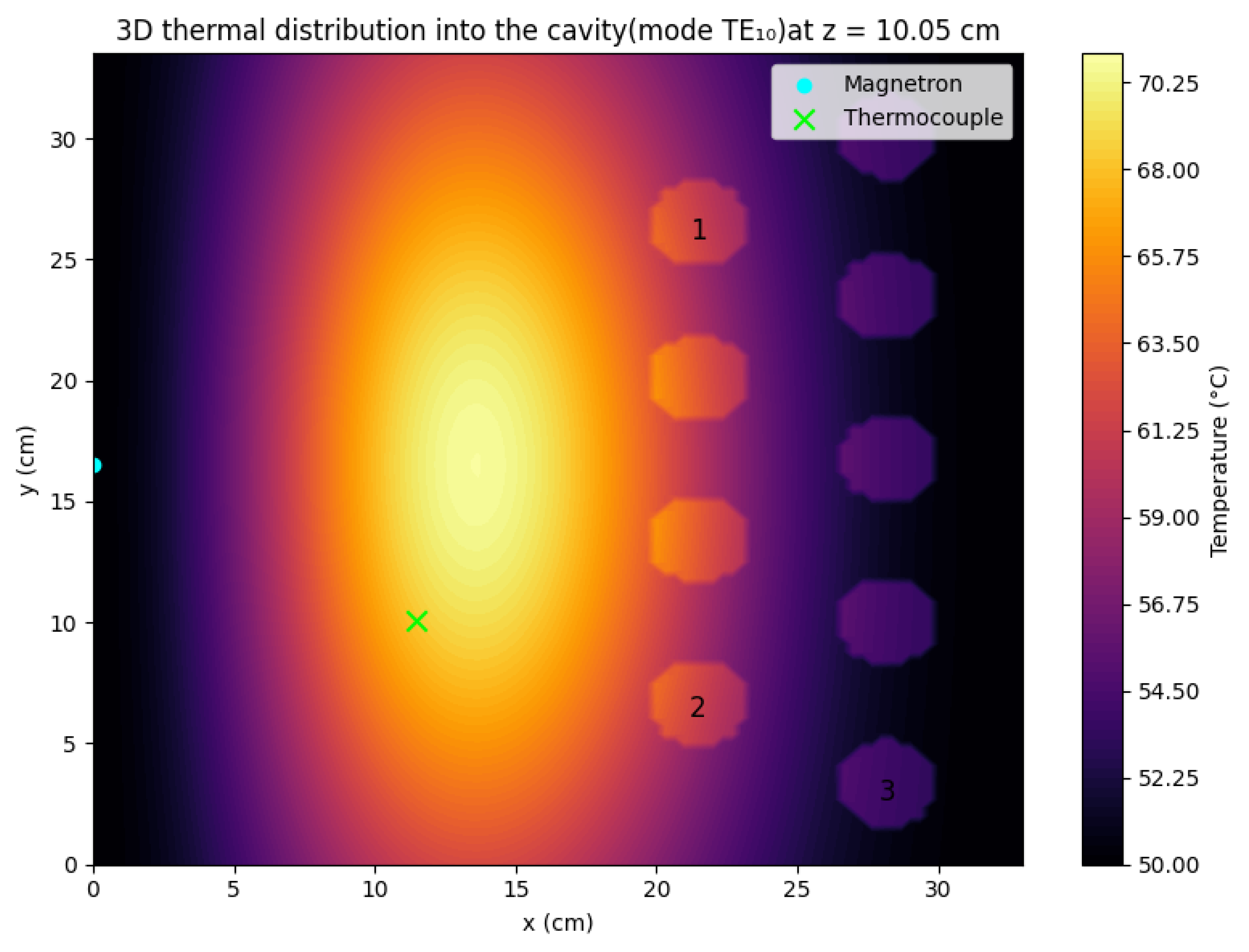
- Yang, B.; Huang, H.; Zhou, L.; Jin, H. Method for Solving the Microwave Heating Temperature Distribution of the TE10 Mode. Processes 2022, 10, 1377. [Google Scholar] [CrossRef]
- Thostenson, E.T.; Chou, T.W. Microwave Processing: Fundamentals and Applications. Compos. Part. A Appl. Sci. Manuf. 1999, 30, 1055–1071. [Google Scholar] [CrossRef]
- Fromenteze, T.; Yurduseven, O.; Imani, M.F.; Gollub, J.; Decroze, C.; Carsenat, D.; Smith, D.R. Computational Imaging Using a Mode-Mixing Cavity at Microwave Frequencies. Appl. Phys. Lett. 2015, 106, 194104. [Google Scholar] [CrossRef]
- Wu, K.; Zhu, L.; Vahldieck, R. Microwave Passive Components. In The Electrical Engineering Handbook; Chen, W., Ed.; Academic Press: New York, NY, USA, 2005; pp. 585–618. ISBN 0-12-170960-4. [Google Scholar]


| Dimension a (m) | Dimension b (m) | Dimension c (m) | Power (W) | Frequency (MHz) | T (°C) | Wall Material |
|---|---|---|---|---|---|---|
| 0.33 | 0.21 | 0.34 | 700 | 2450 | 68 | Stainless still |
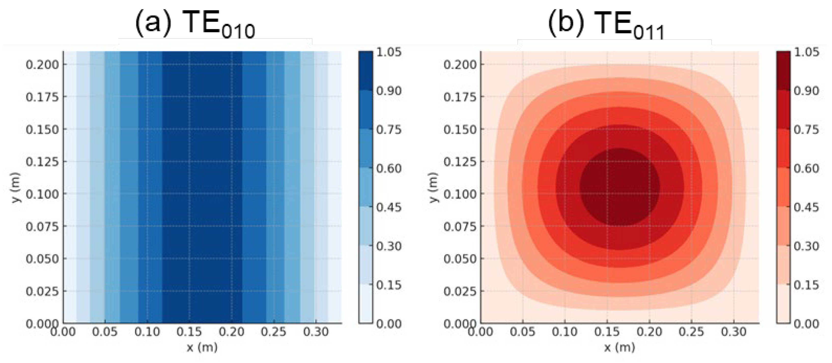
| Mode | (GHz) | Mode | (GHz) | Mode | (GHz) | |
|---|---|---|---|---|---|---|
| Basic modes | TE001 | 0.448 GHz | TE100 | 0.454 GHz | TE010 | 0.714 GHz |
| Mixed modes | TE101 | 0.641 GHz | TE011 | 0.834 GHz | TE110 | 0.844 GHz |
| TE200 | 0.908 GHz | TE111 | 1.006 GHz | TE201 | 1.041 GHz | |
| TE210 | 1.097 GHz | TE211 | 1.246 GHz | TE102 | 1.314 GHz | |
| TE300 | 1.360 GHz | TE020 | 1.430 GHz | TE301 | 1.457 GHz | |
| TE202 | 1.556 GHz | TE112 | 1.588 GHz | TE310 | 1.591 GHz | |
| TE120 | 1.592 GHz | TE021 | 1.629 GHz | TE311 | 1.777 GHz | |
| TE220 | 1.788 GHz | TE212 | 1.839 GHz | TE302 | 1.892 GHz | |
| TE221 | 1.934 GHz | TE113 | 1.967 GHz | TE121 | 2.003 GHz | |
| TE320 | 2.134 GHz | TE130 | 2.145 GHz | TE213 | 2.287 GHz | |
| TE321 | 2.299 GHz | TE114 | 2.300 GHz | TE230 | 2.337 GHz | |
| TE131 | 2.408 GHz |
Disclaimer/Publisher’s Note: The statements, opinions and data contained in all publications are solely those of the individual author(s) and contributor(s) and not of MDPI and/or the editor(s). MDPI and/or the editor(s) disclaim responsibility for any injury to people or property resulting from any ideas, methods, instructions or products referred to in the content. |
© 2025 by the authors. Licensee MDPI, Basel, Switzerland. This article is an open access article distributed under the terms and conditions of the Creative Commons Attribution (CC BY) license (https://creativecommons.org/licenses/by/4.0/).
Share and Cite
González-Lavín, J.; Arenillas, A.; Rey-Raap, N. Overcoming Scaling Challenges in Sol–Gel Synthesis: A Microwave-Assisted Approach for Iron-Based Energy Materials. Microwave 2025, 1, 6. https://doi.org/10.3390/microwave1020006
González-Lavín J, Arenillas A, Rey-Raap N. Overcoming Scaling Challenges in Sol–Gel Synthesis: A Microwave-Assisted Approach for Iron-Based Energy Materials. Microwave. 2025; 1(2):6. https://doi.org/10.3390/microwave1020006
Chicago/Turabian StyleGonzález-Lavín, Judith, Ana Arenillas, and Natalia Rey-Raap. 2025. "Overcoming Scaling Challenges in Sol–Gel Synthesis: A Microwave-Assisted Approach for Iron-Based Energy Materials" Microwave 1, no. 2: 6. https://doi.org/10.3390/microwave1020006
APA StyleGonzález-Lavín, J., Arenillas, A., & Rey-Raap, N. (2025). Overcoming Scaling Challenges in Sol–Gel Synthesis: A Microwave-Assisted Approach for Iron-Based Energy Materials. Microwave, 1(2), 6. https://doi.org/10.3390/microwave1020006