
Low-Power Rectennas in Microwave Wireless Power Transmission


Abstract
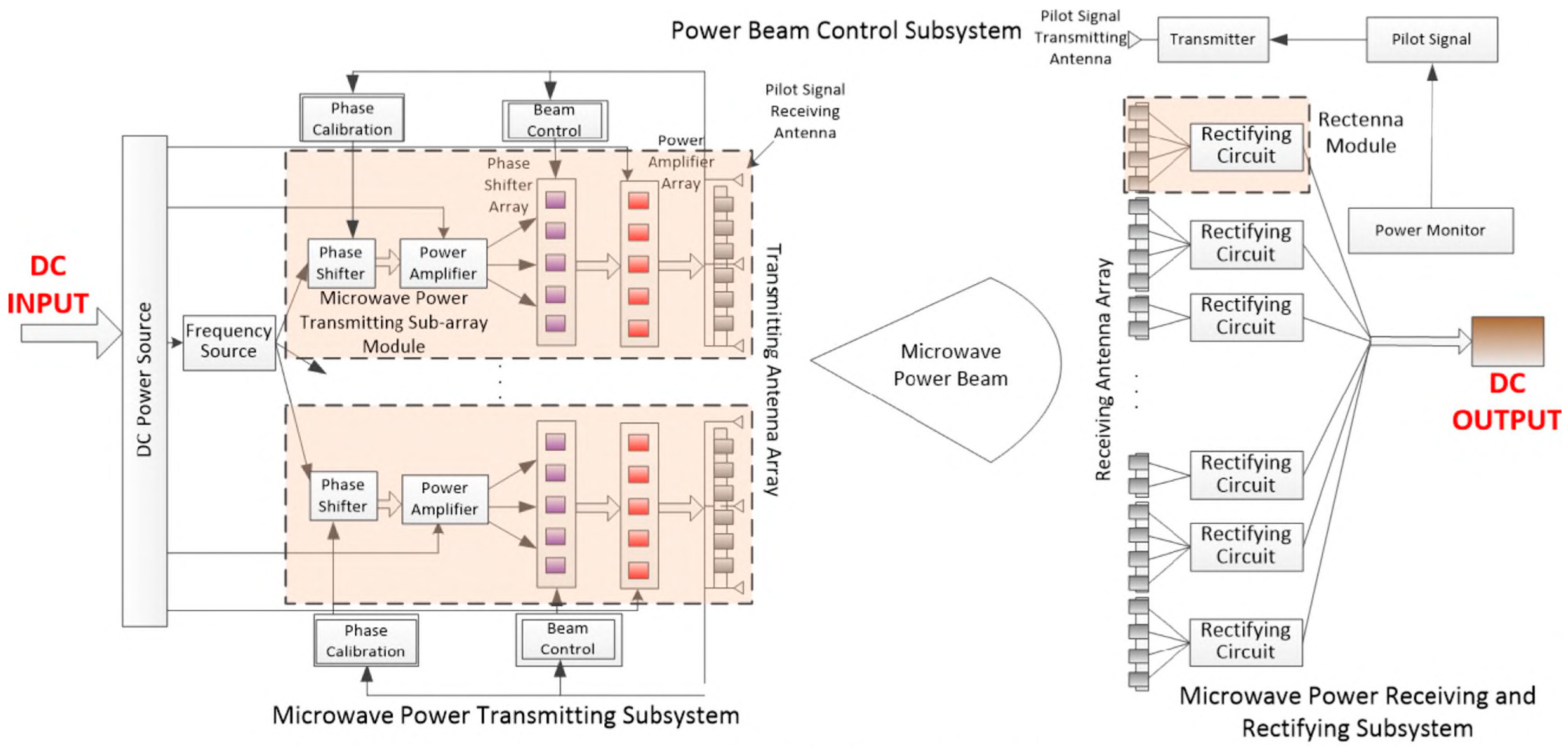
1. Introduction
2. Low-Power Rectifiers
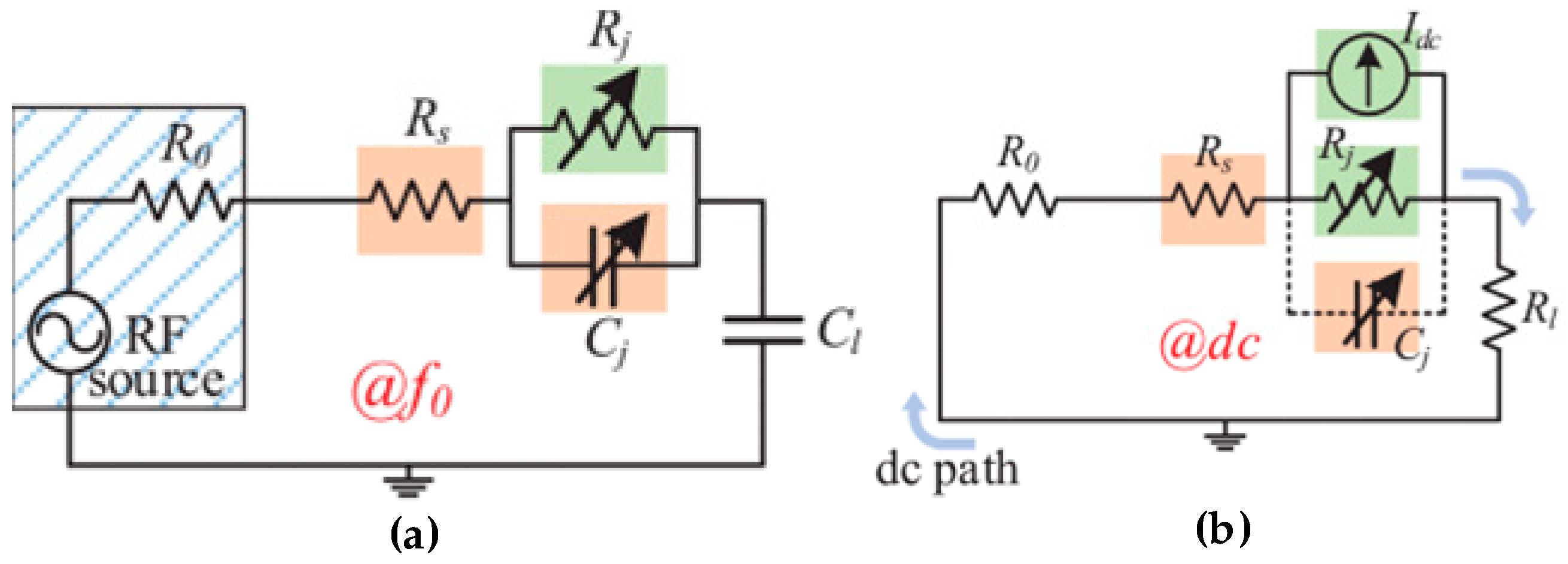
2.1. Diode Performance Optimization
2.1.1. Input Signal Manipulation
2.1.2. High-Nonlinearity Device Selection
2.2. Matching Network Enhancement
2.2.1. Robust Matching Network Deployment
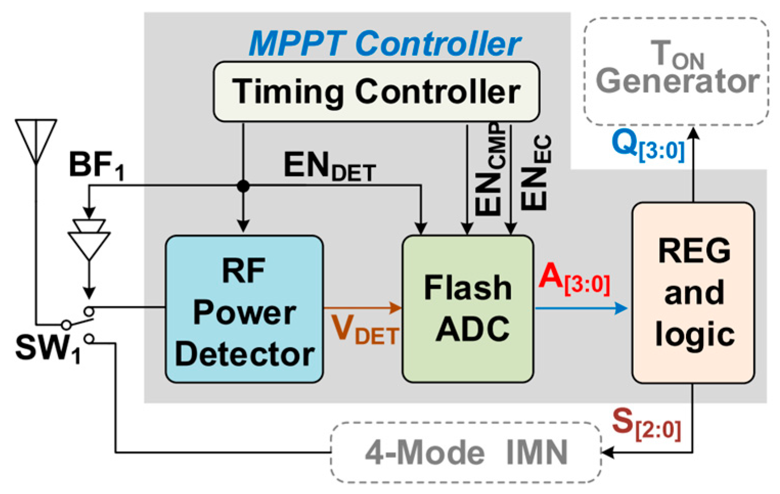
2.2.2. Dynamic DC-Load Matching
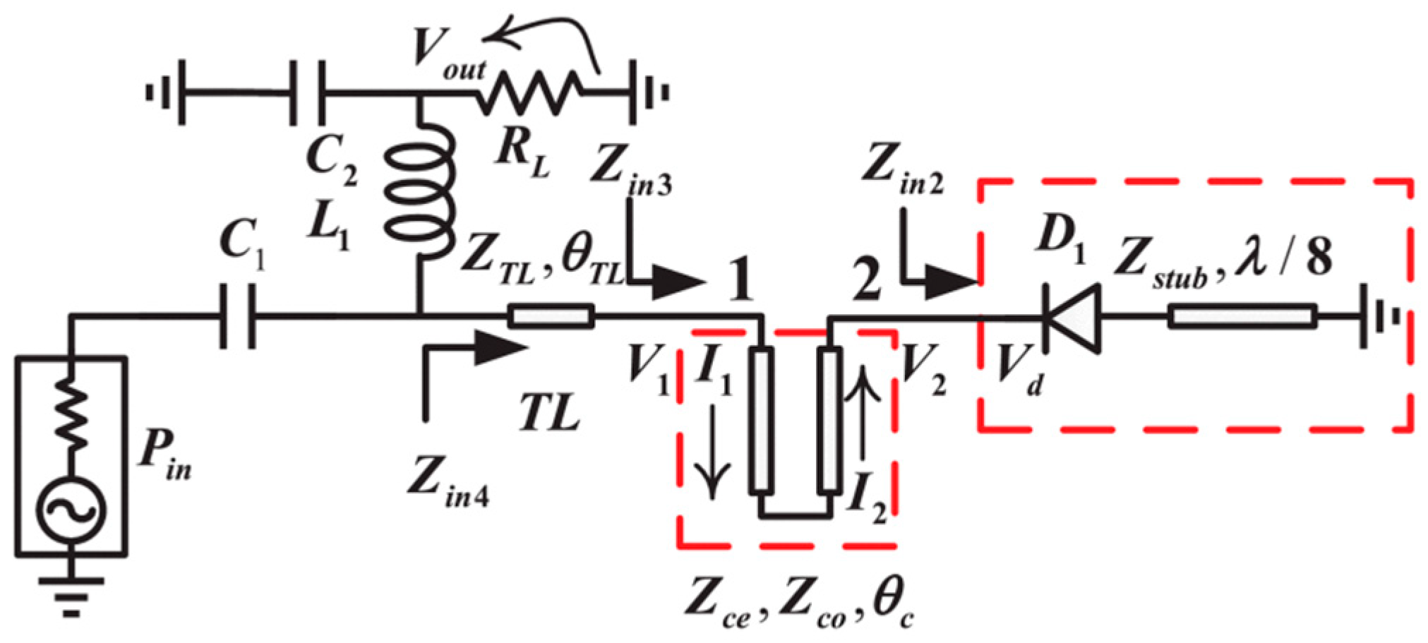
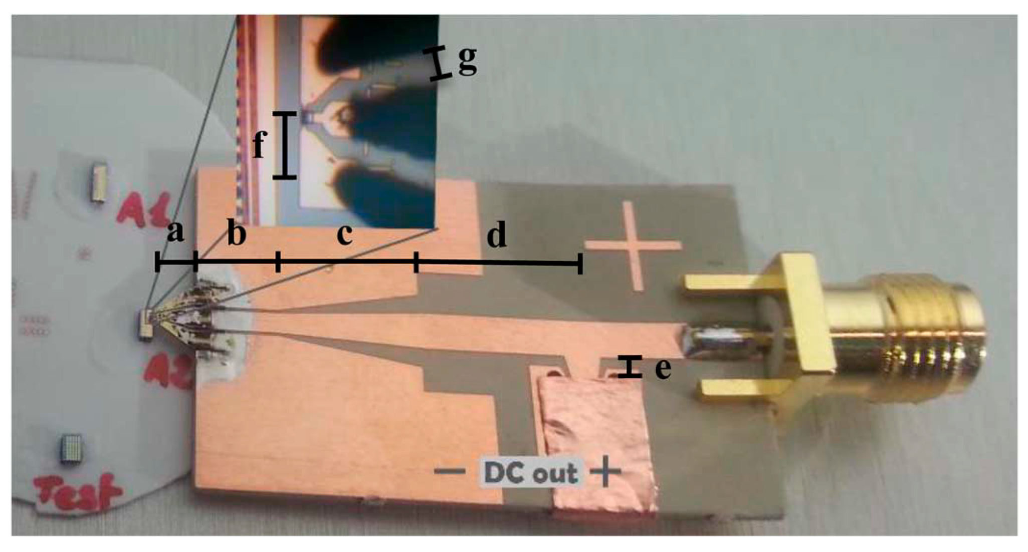
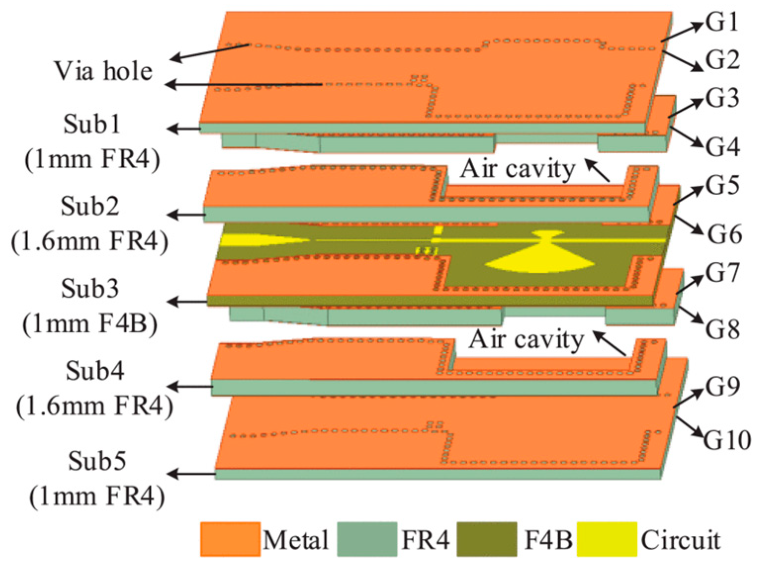
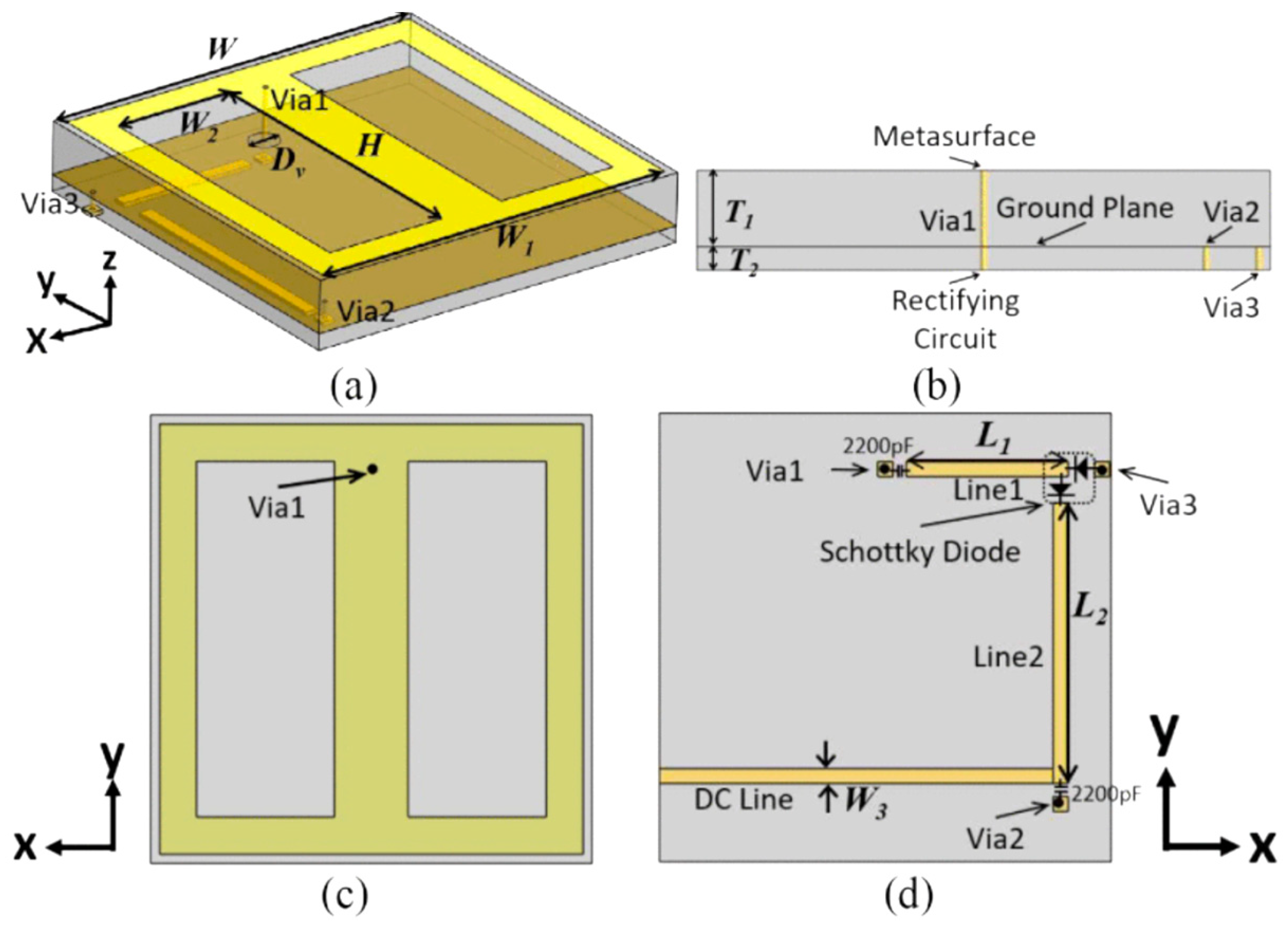
2.2.3. Direct Antenna-to-Rectifier Matching
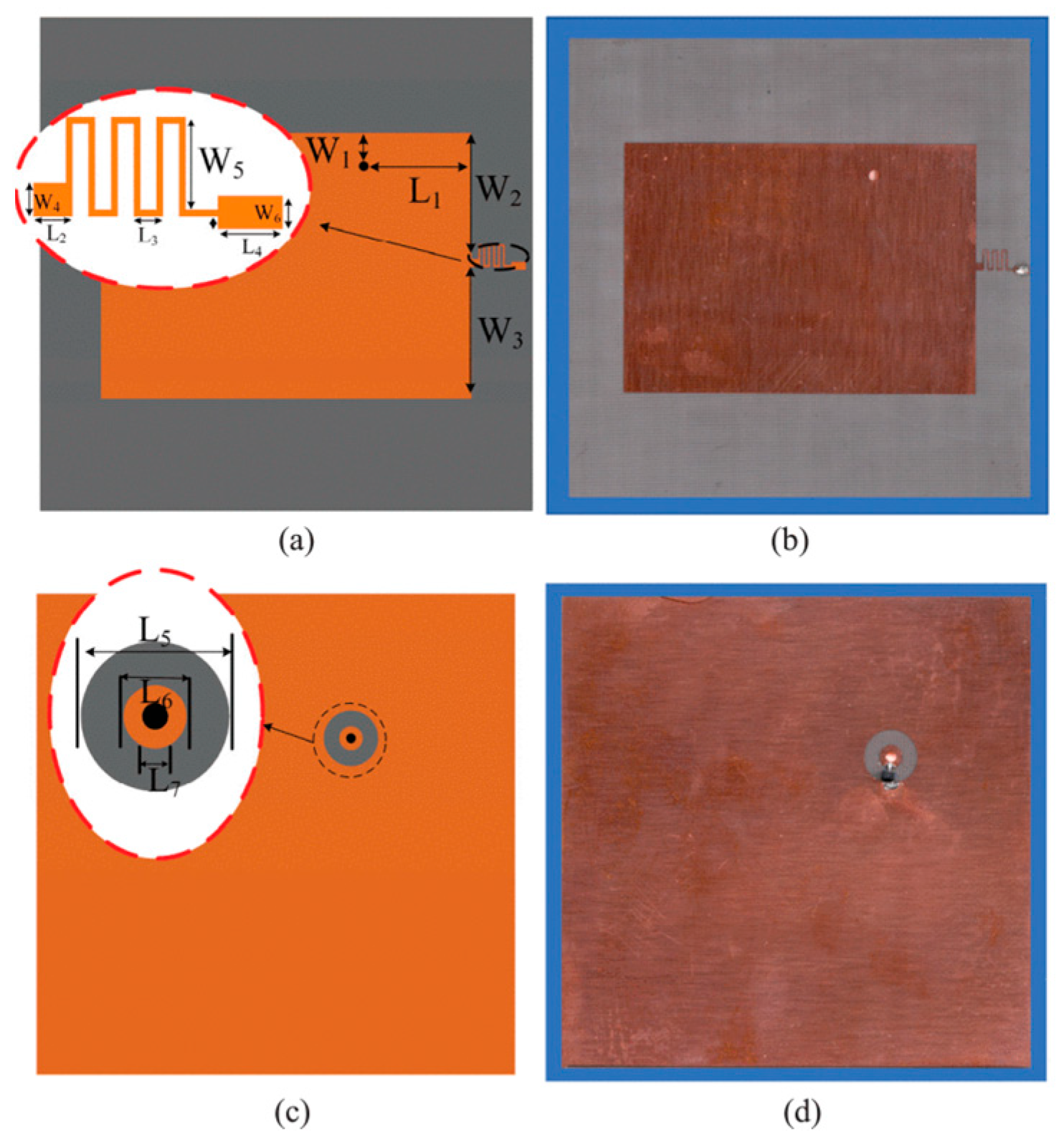
2.2.4. Low-Loss Structure Utilization
3. Low-Power-Density Rectenna
3.1. High-Gain Antenna Design
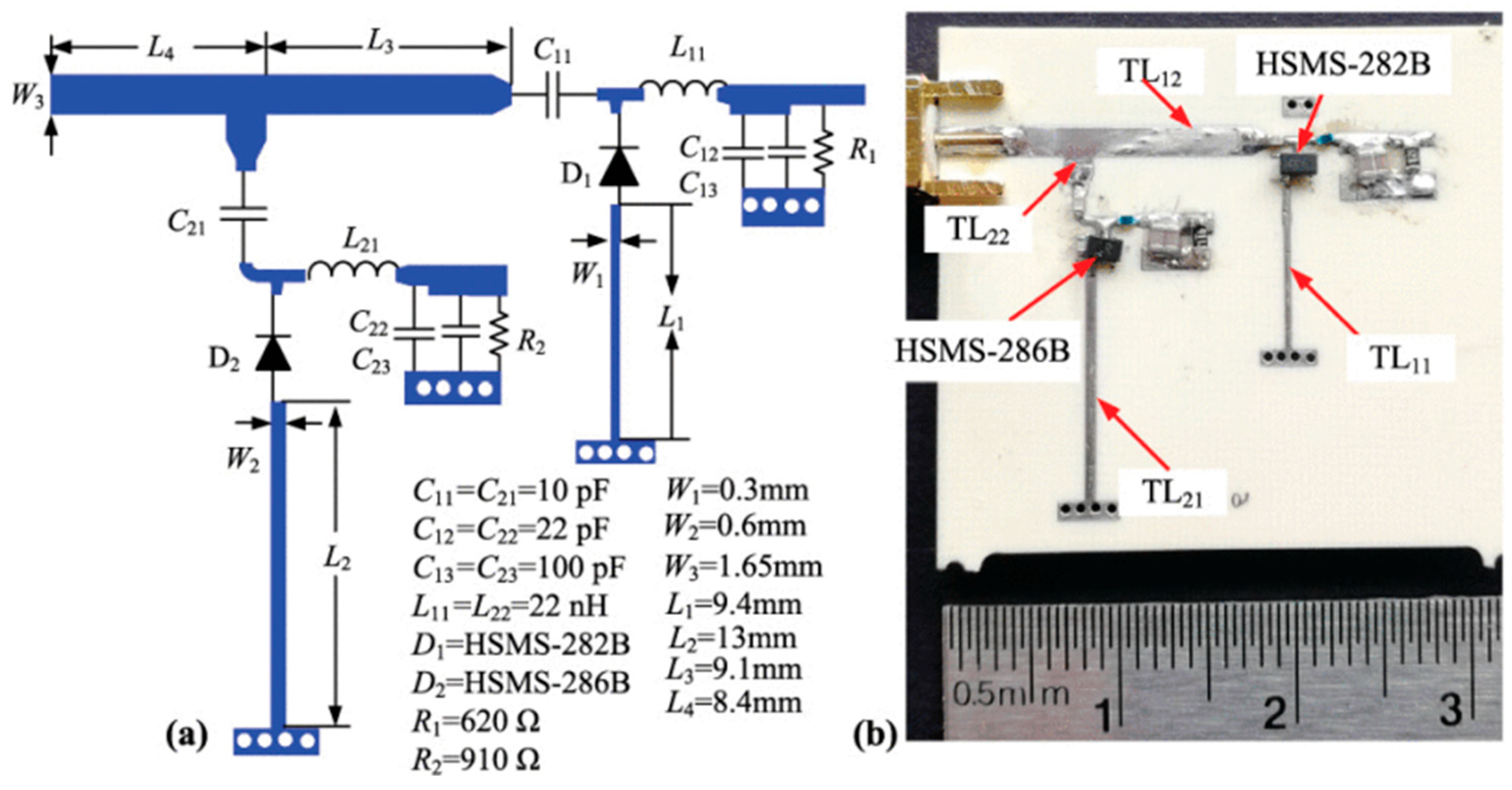
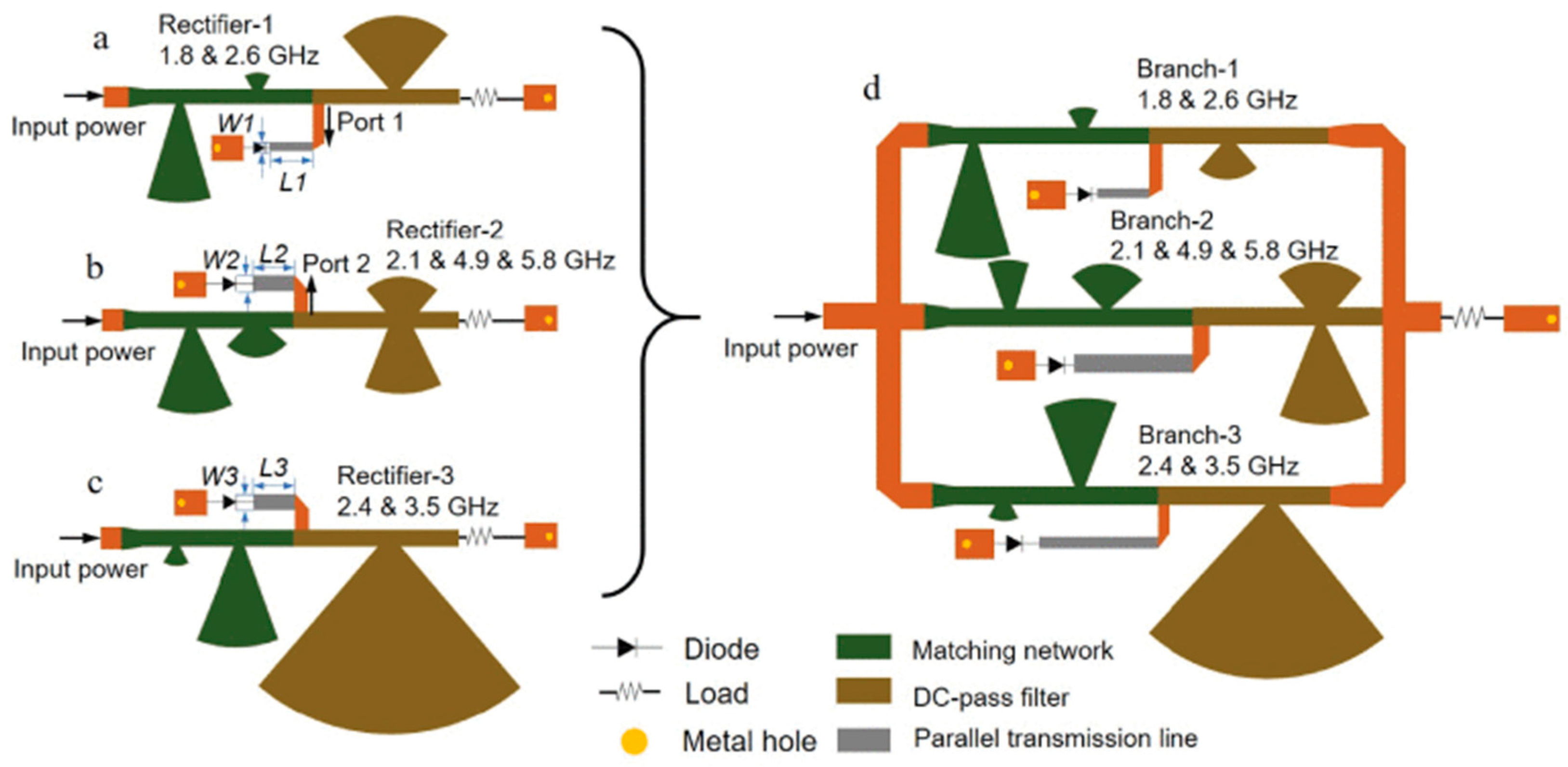
3.2. Multi-/Wideband Rectenna Configurations
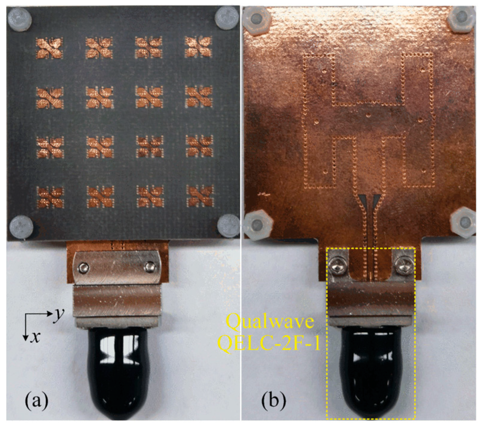
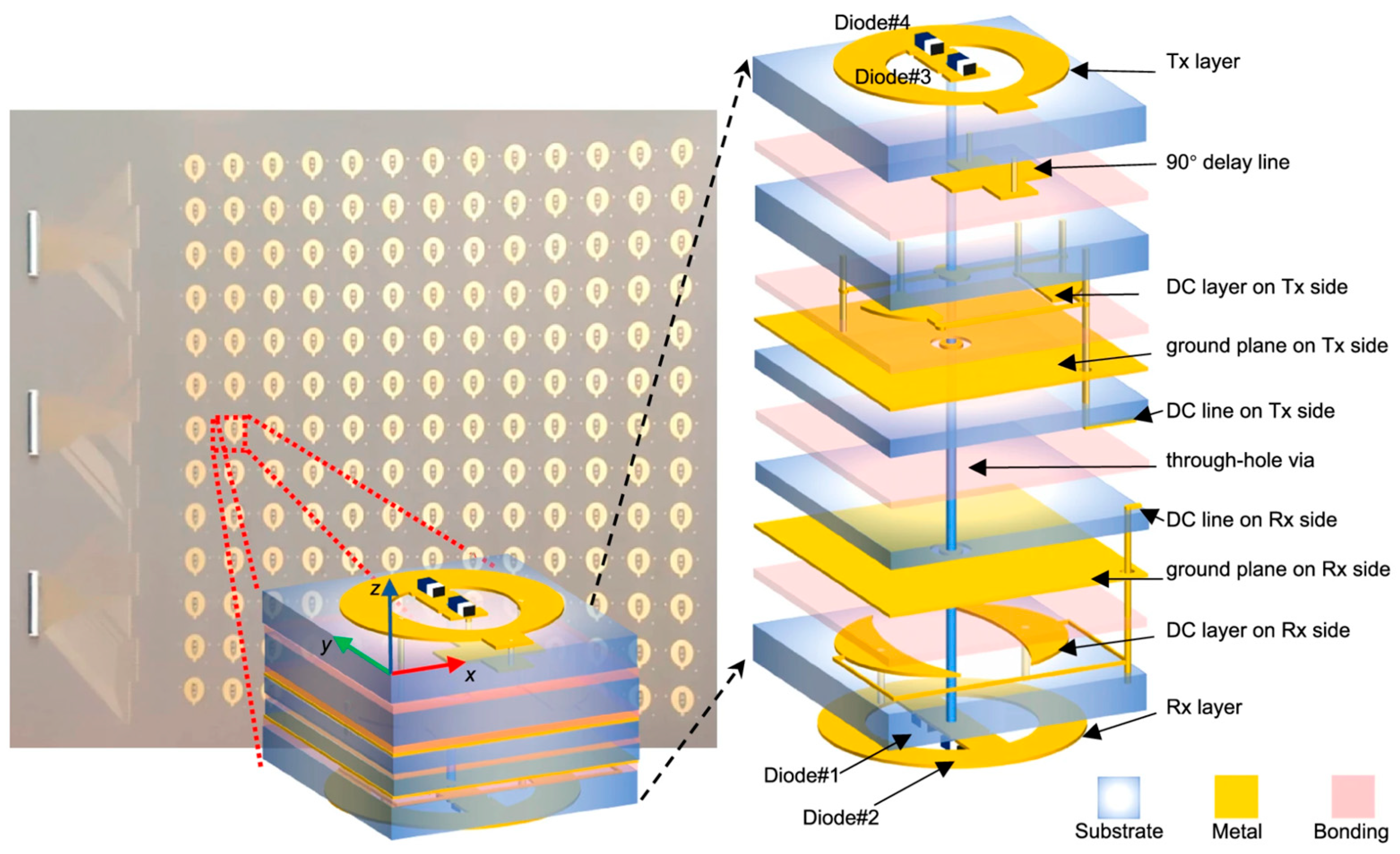
3.3. Multi-Polarization Rectenna Implementations
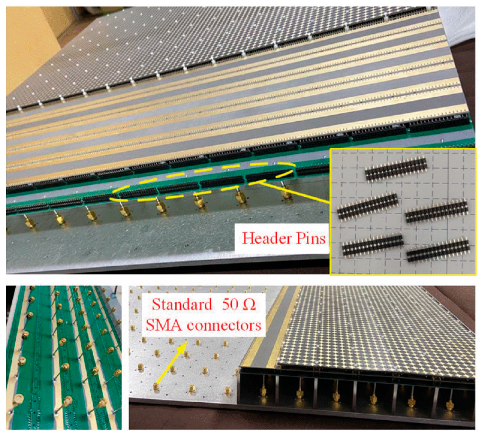
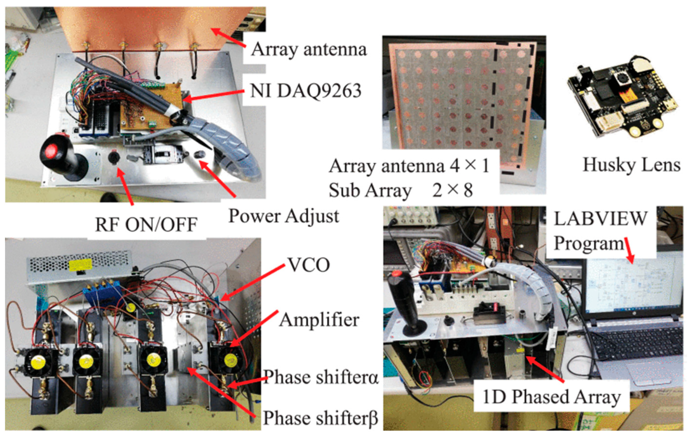
3.4. Beamforming Techniques
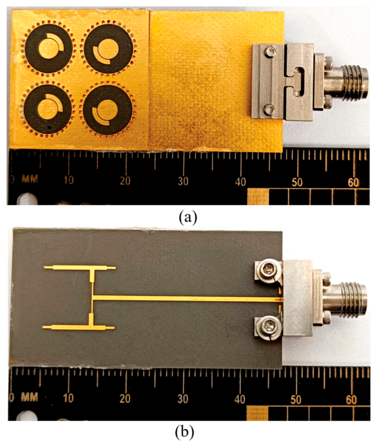
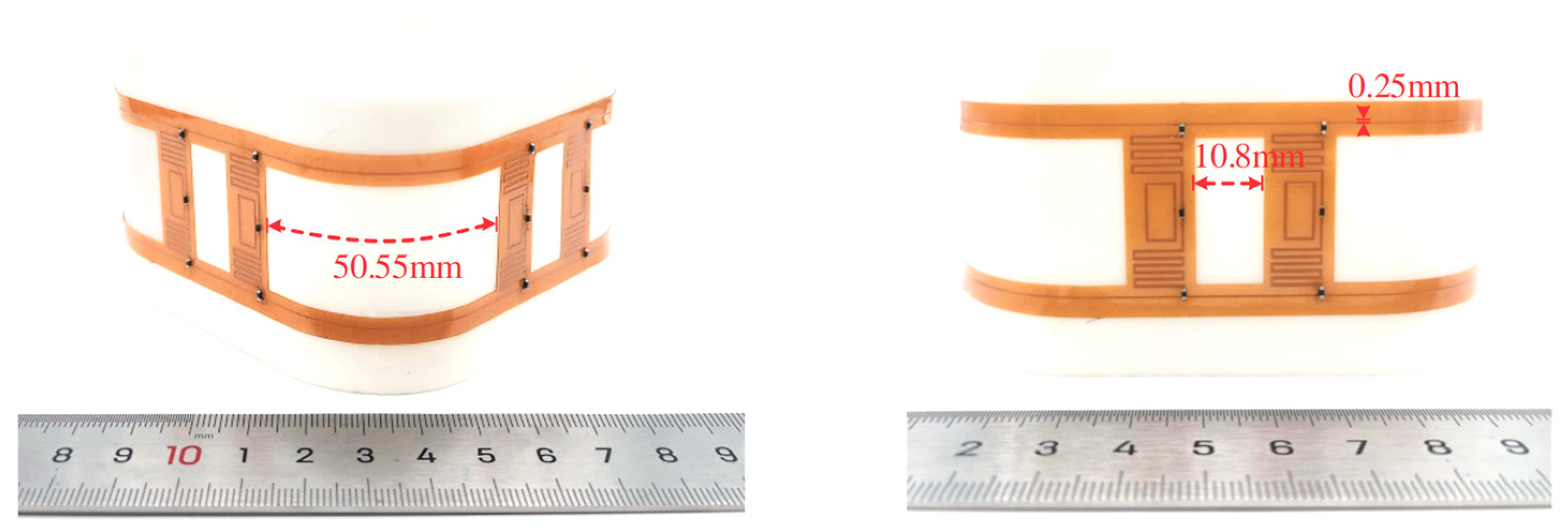
3.5. Advanced Functional Antenna Structures
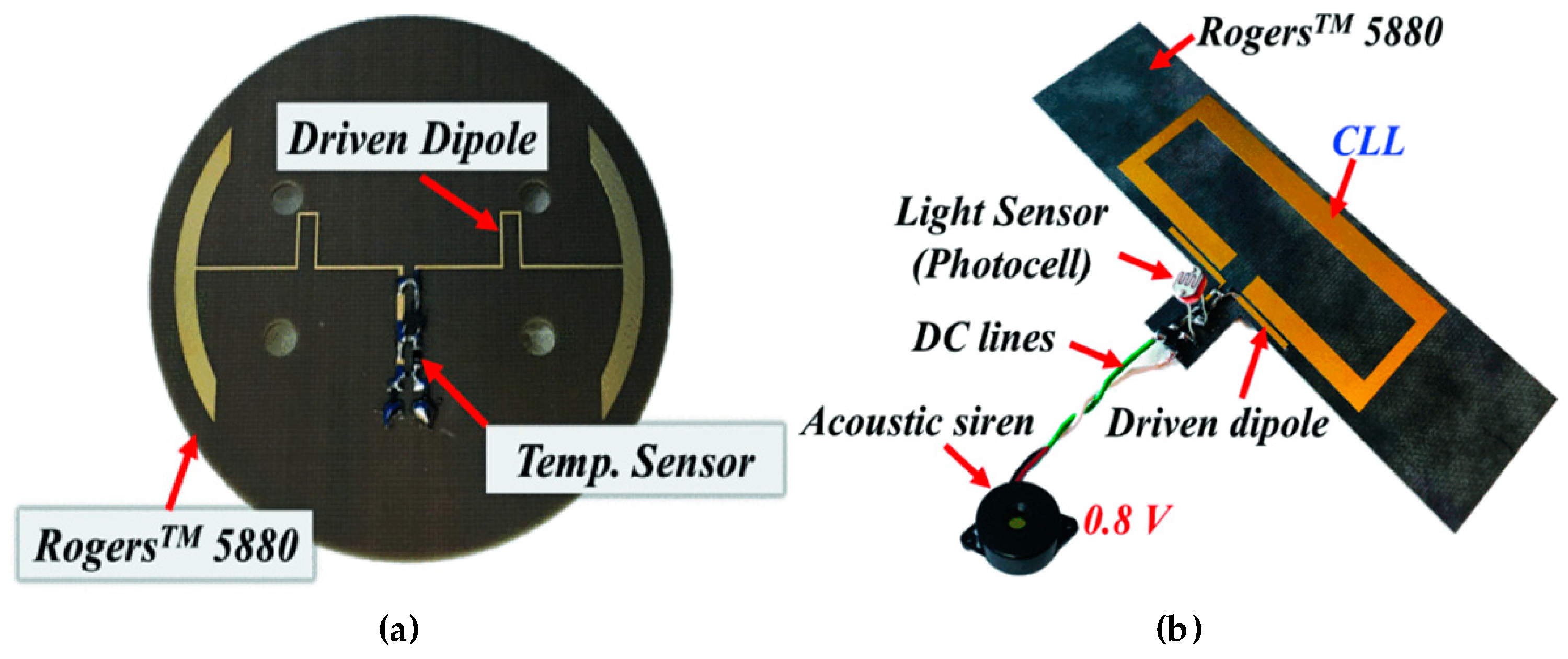
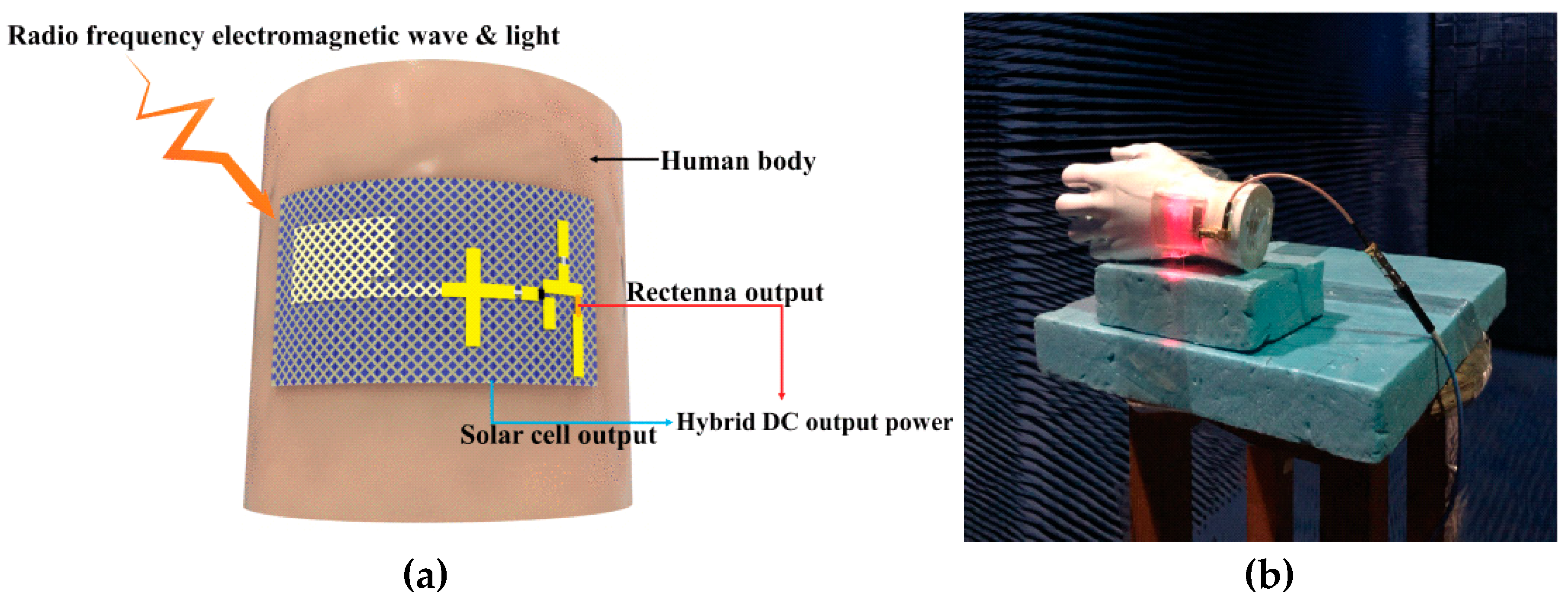
4. Emerging Application Scenarios
5. Conclusions
Funding
Data Availability Statement
Conflicts of Interest
References
- Popovic, Z.; Falkenstein, E.A.; Costinett, D.; Zane, R. Low-Power Far-Field Wireless Powering for Wireless Sensors. Proc. IEEE 2013, 101, 1397–1409. [Google Scholar] [CrossRef]
- Khan, A.N.; Cha, Y.-O.; Giddens, H.; Hao, Y. Recent Advances in Organ-Specific Wireless Bioelectronic Devices: Perspective on Biotelemetry and Power Transfer Using Antenna Systems. Engineering 2022, 11, 27–41. [Google Scholar] [CrossRef]
- Tesla, N. The transmission of electric energy without wires. Electr. World Eng. 1904, 1, 21–24. [Google Scholar] [CrossRef]
- Kurs, A.; Karalis, A.; Moffatt, R.; Joannopoulos, J.D.; Fisher, P.; Soljačić, M. Wireless power transfer via strongly coupled magnetic resonances. Science 2007, 317, 83–86. [Google Scholar] [CrossRef] [PubMed]
- Brown, W.C. Free-space transmission. IEEE Spectr. 1964, 1, 86–91. [Google Scholar] [CrossRef]
- Pinuela, M.; Mitcheson, P.D.; Lucyszyn, S. Ambient RF energy harvesting in urban and semi-urban environments,” IEEE Trans. Microw. IEEE Trans. Microw. Theory Tech. 2013, 61, 2715–2726. [Google Scholar] [CrossRef]
- Belo, D.; Ribeiro, D.C.; Pinho, P.; Carvalho, N.B. A Selective, Tracking, and Power Adaptive Far-Field Wireless Power Transfer System. IEEE Trans. Microw. Theory Tech. 2019, 67, 3856–3866. [Google Scholar] [CrossRef]
- Shinohara, N. History and innovation of wireless power transfer via microwaves. IEEE J. Microw. 2021, 1, 218–228. [Google Scholar] [CrossRef]
- Kim, S.; Vyas, R.; Bito, J.; Niotaki, K.; Collado, A.; Georgiadis, A.; Tentzeris, M.M. Ambient RF Energy-Harvesting Technologies for Self-Sustainable Standalone Wireless Sensor Platforms. Proc. IEEE 2014, 102, 1649–1666. [Google Scholar] [CrossRef]
- Yoo, T.-W.; Chang, K. Theoretical and experimental development of 10 and 35 GHz rectennas. IEEE Trans. Microw. Theory Tech. 1992, 40, 1259–1266. [Google Scholar] [CrossRef]
- McSpadden, J.; Fan, L.; Chang, K. Design and experiments of a high-conversion-efficiency 5.8-GHz rectenna. IEEE Trans. Microw. Theory Tech. 1998, 46, 2053–2060. [Google Scholar] [CrossRef]
- Gu, X.; Hemour, S.; Wu, K. Far-Field Wireless Power Harvesting: Nonlinear Modeling, Rectenna Design, and Emerging Applications. Proc. IEEE 2021, 110, 56–73. [Google Scholar] [CrossRef]
- Hemour, S.; Zhao, Y.; Lorenz, C.H.P.; Houssameddine, D.; Gui, Y.; Hu, C.-M.; Wu, K. Towards Low-Power High-Efficiency RF and Microwave Energy Harvesting. IEEE Trans. Microw. Theory Tech. 2014, 62, 965–976. [Google Scholar] [CrossRef]
- Lorenz, C.H.P.; Hemour, S.; Wu, K. Physical Mechanism and Theoretical Foundation of Ambient RF Power Harvesting Using Zero-Bias Diodes. IEEE Trans. Microw. Theory Tech. 2016, 64, 2146–2158. [Google Scholar] [CrossRef]
- Zhao, F.; Inserra, D.; Gao, G.; Huang, Y.; Li, J.; Wen, G. High-Efficiency Microwave Rectifier With Coupled Transmission Line for Low-Power Energy Harvesting and Wireless Power Transmission. IEEE Trans. Microw. Theory Tech. 2020, 69, 916–925. [Google Scholar] [CrossRef]
- Liu, D.; Wang, L.; He, Z.; Liu, C. A Self-Packaged SISL Low-Power Rectifier Based on a High-Impedance Line for C-Band Applications. IEEE Microw. Wirel. Technol. Lett. 2022, 33, 212–215. [Google Scholar] [CrossRef]
- Boaventura, A.S.; Carvalho, N.B. Maximizing DC power in energy harvesting circuits using multisine excitation. In Proceedings of the 2011 IEEE MTT-S International Microwave Symposium, Baltimore, MD, USA, 5–10 June 2011; pp. 1–4. [Google Scholar] [CrossRef]
- He, Z.; Trovarello, S.; Benassi, F.; Masotti, D.; Liu, C.; Costanzo, A. Analysis of Rectifiers Under Various Multitone Excitations and Using Different Diodes in Low-Power Conditions. In Proceedings of the 2022 IEEE 12th International Conference on RFID Technology and Applications (RFID-TA), Cagliari, Italy, 12–14 September 2022; pp. 157–160. [Google Scholar] [CrossRef]
- Boaventura, A.J.S.; Collado, A.; Georgiadis, A.; Carvalho, N.B. Spatial Power Combining of Multi-Sine Signals for Wireless Power Transmission Applications. IEEE Trans. Microw. Theory Tech. 2014, 62, 1022–1030. [Google Scholar] [CrossRef]
- Collado, A.; Georgiadis, A. Optimal Waveforms for Efficient Wireless Power Transmission. IEEE Microw. Wirel. Compon. Lett. 2014, 24, 354–356. [Google Scholar] [CrossRef]
- Valenta, C.R.; Morys, M.M.; Durgin, G.D. Theoretical Energy-Conversion Efficiency for Energy-Harvesting Circuits Under Power-Optimized Waveform Excitation. IEEE Trans. Microw. Theory Tech. 2015, 63, 1758–1767. [Google Scholar] [CrossRef]
- Azarbahram, A.; López, O.L.A.; Latva-Aho, M. Waveform Optimization and Beam Focusing for Near-Field Wireless Power Transfer With Dynamic Metasurface Antennas and Non-Linear Energy Harvesters. IEEE Trans. Wirel. Commun. 2025, 24, 1031–1045. [Google Scholar] [CrossRef]
- Eidaks, J.; Kusnins, R.; Babajans, R.; Cirjulina, D.; Semenjako, J.; Litvinenko, A. Fast and Accurate Approach to RF-DC Conversion Efficiency Estimation for Multi-Tone Signals. Sensors 2022, 22, 787. [Google Scholar] [CrossRef]
- Mouris, B.A.; Ghauch, H.; Thobaben, R.; Jonsson, B.L.G. Multi-Tone Signal Optimization for Wireless Power Transfer in the Presence of Wireless Communication Links. IEEE Trans. Wirel. Commun. 2020, 19, 3575–3590. [Google Scholar] [CrossRef]
- Varshney, L.R. Transporting information and energy simultaneously. In Proceedings of the 2008 IEEE International Symposium on Information Theory, Toronto, ON, Canada, 6–11 July 2008; pp. 1612–1616. [Google Scholar] [CrossRef]
- Claessens, S.; Pan, N.; Rajabi, M.; Schreurs, D.; Pollin, S. Enhanced Biased ASK Modulation Performance for SWIPT With AWGN Channel and Dual-Purpose Hardware. IEEE Trans. Microw. Theory Tech. 2018, 66, 3478–3486. [Google Scholar] [CrossRef]
- Debels, E.; Moeneclaey, M. Optimized Linear and Non-Linear Precoding for Biased ASK Modulation in Multiuser SWIPT With Integrated Receiver. IEEE Trans. Commun. 2022, 70, 6083–6094. [Google Scholar] [CrossRef]
- Claessens, S.; Pan, N.; Schreurs, D.; Pollin, S. Multitone FSK Modulation for SWIPT. IEEE Trans. Microw. Theory Tech. 2019, 67, 1665–1674. [Google Scholar] [CrossRef]
- Qaragoez, Y.; Pollin, S.; Schreurs, D. Biased-FSK Modulation for Simultaneous Wireless Information and Power Transfer. IEEE Trans. Microw. Theory Tech. 2024, 72, 7071–7084. [Google Scholar] [CrossRef]
- Dhull, P.; Schreurs, D.; Paolini, G.; Costanzo, A.; Abolhasan, M.; Shariati, N. Multitone PSK Modulation Design for Simultaneous Wireless Information and Power Transfer. IEEE Trans. Microw. Theory Tech. 2024, 72, 446–460. [Google Scholar] [CrossRef]
- Ayir, N.; Riihonen, T.; Heino, M. Practical Waveform-to-Energy Harvesting Model and Transmit Waveform Optimization for RF Wireless Power Transfer Systems. IEEE Trans. Microw. Theory Tech. 2023, 71, 5498–5514. [Google Scholar] [CrossRef]
- Niotaki, K.; Collado, A.; Georgiadis, A.; Kim, S.; Tentzeris, M.M. Solar/Electromagnetic Energy Harvesting and Wireless Power Transmission. Proc. IEEE 2014, 102, 1712–1722. [Google Scholar] [CrossRef]
- Collado, A.; Georgiadis, A. Conformal Hybrid Solar and Electromagnetic (EM) Energy Harvesting Rectenna. IEEE Trans. Circuits Syst. I Regul. Pap. 2013, 60, 2225–2234. [Google Scholar] [CrossRef]
- Zhang, Y.; Shen, S.; Chiu, C.Y.; Murch, R. Hybrid RF-Solar Energy Harvesting Systems Utilizing Transparent Multiport Micromeshed Antennas. IEEE Trans. Microw. Theory Tech. 2019, 67, 4534–4546. [Google Scholar] [CrossRef]
- Shi, Y.; Nan, Y.H. Hybrid Power Harvesting From Ambient Radiofrequency and Solar Energy. IEEE Antennas Wirel. Propag. Lett. 2022, 21, 2382–2386. [Google Scholar] [CrossRef]
- Zeng, B.H.; Zheng, S.Y.; Chan, W.S. Single-and Wide-Band Cooperative Rectifiers Harvesting Ambient Electromagnetic-Photovoltaic Energy for Powering Battery-Less Sensors. IEEE Internet Things J. 2025. early access. [Google Scholar] [CrossRef]
- Guo, L.; Gu, X.; Chu, P.; Hemour, S.; Wu, K. Collaboratively Harvesting Ambient Radiofrequency and Thermal Energy. IEEE Trans. Ind. Electron. 2020, 67, 3736–3746. [Google Scholar] [CrossRef]
- Liu, Z.; Hsu, Y.-P.; Hella, M.M. A Thermal/RF Hybrid Energy Harvesting System With Rectifying-Combination and Improved Fractional-OCV MPPT Method. IEEE Trans. Circuits Syst. I Regul. Pap. 2020, 67, 3352–3363. [Google Scholar] [CrossRef]
- Bakytbekov, A.; Nguyen, T.Q.; Zhang, G.; Strano, M.S.; Salama, K.N.; Shamim, A. Dual-Function Triple-Band Heatsink Antenna for Ambient RF and Thermal Energy Harvesting. IEEE Open J. Antennas Propag. 2022, 3, 263–273. [Google Scholar] [CrossRef]
- Lorenz, C.H.P.; Hemour, S.; Liu, W.; Badel, A.; Formosa, F.; Wu, K. Hybrid Power Harvesting for Increased Power Conversion Efficiency. IEEE Microw. Wirel. Compon. Lett. 2015, 25, 687–689. [Google Scholar] [CrossRef]
- Gu, X.; Hemour, S.; Wu, K. Enabling Far-Field Ambient Energy Harvesting Through Multi-Physical Sources. In Proceedings of the 2018 Asia-Pacific Microwave Conference (APMC), Kyoto, Japan, 6–9 November 2018; pp. 204–206. [Google Scholar] [CrossRef]
- Nguyen, S.; Amirtharajah, R. A hybrid RF and vibration energy harvester for wearable devices. In Proceedings of the 2018 IEEE Applied Power Electronics Conference and Exposition (APEC), San Antonio, TX, USA, 4–8 March 2018; pp. 1060–1064. [Google Scholar] [CrossRef]
- Xiong, J.; Xia, Y.; Chen, Z.; Xia, H.; Xiao, C. Self-Powered Multiinput Hybrid Rectifier With Arbitrary Phase Difference and Low Start-Up Voltage for Piezoelectric Energy Harvesting. IEEE Trans. Power Electron. 2025, 40, 4461–4472. [Google Scholar] [CrossRef]
- Torrey, H.C.; Whitmer, C.A.; Goudsmit, S.A. Crystal Rectifiers; McGraw-Hill: New York, NY, USA, 1948. [Google Scholar]
- Lorenz, C.H.P.; Hemour, S.; Li, W.; Xie, Y.; Gauthier, J.; Fay, P.; Wu, K. Breaking the Efficiency Barrier for Ambient Microwave Power Harvesting With Heterojunction Backward Tunnel Diodes. IEEE Trans. Microw. Theory Tech. 2015, 63, 4544–4555. [Google Scholar] [CrossRef]
- Yan, H.; Wu, S.; Chen, Y.; Xiao, Y.; Xiong, K.; Zhao, Q.; Tang, M.; Jiao, H.; Lin, T.; Shen, H.; et al. Negative capacitance tunneling field-effect transistor for logic electronics and photodetection devices. Appl. Mater. Today 2025, 44, 102737. [Google Scholar] [CrossRef]
- Alshehri, A.H.; Shahin, A.; Mistry, K.; Ibrahim, K.H.; Yavuz, M.; Musselman, K.P. Metal-Insulator-Insulator-Metal Diodes with Responsivities Greater Than 30 A W−1 Based on Nitrogen-Doped TiOx and AlOx Insulator Layers. Adv. Electron. Mater. 2021, 7, 2100467. [Google Scholar] [CrossRef]
- Belkadi, A.; Weerakkody, A.; Moddel, G. Demonstration of resonant tunneling effects in metal-double-insulator-metal (MI2M) diodes. Nat. Commun. 2021, 12, 2925. [Google Scholar] [CrossRef] [PubMed]
- Sharma, R.; Ngo, T.; Raimondo, E.; Giordano, A.; Igarashi, J.; Jinnai, B.; Zhao, S.; Lei, J.; Guo, Y.-X.; Finocchio, G.; et al. Nanoscale spin rectifiers for harvesting ambient radiofrequency energy. Nat. Electron. 2024, 7, 653–661. [Google Scholar] [CrossRef]
- Wu, P.; Chen, Y.-D.; Zhou, W.; Ren, Z.H.; Huang, S.Y. A Wide Dynamic Range Rectifier Array Based on Automatic Input Power Distribution Technique. IEEE Microw. Wirel. Compon. Lett. 2020, 30, 437–440. [Google Scholar] [CrossRef]
- Wu, P.; Huang, S.Y.; Zhou, W.; Liu, C. One Octave Bandwidth Rectifier With a Frequency Selective Diode Array. IEEE Microw. Wirel. Compon. Lett. 2018, 28, 1008–1010. [Google Scholar] [CrossRef]
- He, Z.; Yan, L.; Liu, C. An Adaptive Power Division Strategy for Nonlinear Components in Rectification. IEEE Trans. Power Electron. 2024, 39, 15436–15440. [Google Scholar] [CrossRef]
- He, Z.; Lan, J.; Liu, C. Compact Rectifiers With Ultra-wide Input Power Range Based on Nonlinear Impedance Characteristics of Schottky Diodes. IEEE Trans. Power Electron. 2021, 36, 7407–7411. [Google Scholar] [CrossRef]
- He, H.; Liao, C.; He, Z.; Yan, L.; Liu, C. An Arbitrary-Frequency Dual-Band High-Efficiency Rectifier Employing a Novel Frequency-Selective Power Allocation Network. IEEE Trans. Power Electron. 2025, 40, 8939–8943. [Google Scholar] [CrossRef]
- Guo, L.; Yan, M.; Li, X.; Guan, K.; Chu, P.; Zhao, Y.; Wu, K. RF Power Harvester With Varactor-Enabled Wide-Power-Range Capability for Wireless Power Transfer Applications. IEEE Trans. Microw. Theory Tech. 2025, 73, 1848–1856. [Google Scholar] [CrossRef]
- Wu, P.; Huang, S.Y.; Zhou, W.; Ren, Z.H.; Liu, Z.; Huang, K.; Liu, C. High-Efficient Rectifier With Extended Input Power Range Based on Self-Tuning Impedance Matching. IEEE Microw. Wirel. Compon. Lett. 2018, 28, 1116–1118. [Google Scholar] [CrossRef]
- De-Oliveira, T.C.; Girardi, A.G.; de Aguirre, P.C.C.; Compassi-Severo, L. A 915-MHz RF-EH with Varactor-Based Adaptive Impedance Matching for ULV Batteryless Devices. In Proceedings of the 2023 Argentine Conference on Electronics (CAE), Cordoba, Argentina, 9–10 March 2023; pp. 112–116. [Google Scholar] [CrossRef]
- Wu, P.; Huang, S.Y.; Zhou, W.; Yu, W.; Liu, Z.; Chen, X.; Liu, C. Compact High-Efficiency Broadband Rectifier With Multi-Stage-Transmission-Line Matching. IEEE Trans. Circuits Syst. II Express Briefs 2019, 66, 1316–13209. [Google Scholar] [CrossRef]
- Kimionis, J.; Collado, A.; Tentzeris, M.M.; Georgiadis, A. Octave and Decade Printed UWB Rectifiers Based on Nonuniform Transmission Lines for Energy Harvesting. IEEE Trans. Microw. Theory Tech. 2017, 65, 4326–4334. [Google Scholar] [CrossRef]
- Han, Y.; Leitermann, O.; Jackson, D.A.; Rivas, J.M.; Perreault, D.J. Resistance Compression Networks for Radio-Frequency Power Conversion. IEEE Trans. Power Electron. 2007, 22, 41–53. [Google Scholar] [CrossRef]
- He, H.; Lin, H.; Wu, P.; Li, Q.; Liu, C. Compact High-Efficiency Broadband Rectifier Based on Coupled Transmission Line. IEEE Trans. Circuits Syst. II Express Briefs 2022, 69, 4404–4408. [Google Scholar] [CrossRef]
- Cao, B.; Wu, C.; Zhai, H.; Xu, K.; Chen, Z.; Zhou, R.; Yang, T.; Cai, X.; Li, G. A Dual-Band Rectifier With a Novel Impedance Compression Network for WPT. IEEE Trans. Power Electron. 2025, 40, 7646–7650. [Google Scholar] [CrossRef]
- Song, C.; Huang, Y.; Zhou, J.; Carter, P. Improved Ultrawideband Rectennas Using Hybrid Resistance Compression Technique. IEEE Trans. Antennas Propag. 2017, 65, 2057–2062. [Google Scholar] [CrossRef]
- He, Z.; Liu, C. A Compact High-Efficiency Broadband Rectifier With a Wide Dynamic Range of Input Power for Energy Harvesting. IEEE Microw. Wirel. Compon. Lett. 2020, 30, 433–436. [Google Scholar] [CrossRef]
- Bo, S.F.; Ou, J.-H.; Zhang, X.Y. Ultrawideband Rectifier With Extended Dynamic-Power-Range Based on Wideband Impedance Compression Network. IEEE Trans. Microw. Theory Tech. 2022, 70, 4026–4035. [Google Scholar] [CrossRef]
- Ling, Y.-X.; Tsai, T.-H. A 6.78MHz Wireless Power Transfer System with Maximum Power Tracking over Wide Load Range. In Proceedings of the 2021 International Symposium on VLSI Design, Automation and Test (VLSI-DAT), Hsinchu, Taiwan, 19–22 April 2021; pp. 1–4. [Google Scholar] [CrossRef]
- Zeng, Z.; Estrada-Lopez, J.J.; Abouzied, M.A.; Sanchez-Sinencio, E. A Reconfigurable Rectifier With Optimal Loading Point Determination for RF Energy Harvesting From −22 dBm to −2 dBm. IEEE Trans. Circuits Syst. II Express Briefs 2020, 67, 87–91. [Google Scholar] [CrossRef]
- Liao, X.; Zhang, Y.; Zhang, Y.; Zhang, S.; Zhu, Z.; Liu, L. A High-Efficiency RFEH System With Feedback-Free Fast (F3) MPPT Over a Wide Input Range. IEEE Trans. Circuits Syst. I Regul. Pap. 2025, 72, 2592–2602. [Google Scholar] [CrossRef]
- Guo, L.; Yan, M.; Hu, R.; Du, R.; Chu, P.; Li, Y.; Zhao, Y.; Wu, K. Low RF Power Harvesting Enabled Wireless Sensor Node With Long-Distance Communication Capability. IEEE Trans. Microw. Theory Tech. 2025. early access. [Google Scholar] [CrossRef]
- Wu, P.; Li, Y.; Chen, Y.-D.; Yu, P.-Y.; Cheng, Y.; Liu, C. Compact Rectifier With Wide Range of Output Load Based on Self-Bias Impedance Compensation. IEEE Trans. Power Electron. 2025, 40, 4706–4710. [Google Scholar] [CrossRef]
- Song, C.; Huang, Y.; Zhou, J.; Carter, P.; Yuan, S.; Xu, Q.; Fei, Z. Matching Network Elimination in Broadband Rectennas for High-Efficiency Wireless Power Transfer and Energy Harvesting. IEEE Trans. Ind. Electron. 2017, 64, 3950–3961. [Google Scholar] [CrossRef]
- Fan, R.; Mi, J.; Liu, C. Terrestrial transparent green energy receiving system designed for Space Solar Power Station. Space Sol. Power Wirel. Transm. 2024, 1, 102–107. [Google Scholar] [CrossRef]
- Liu, C.; Lin, H.; He, Z.; Chen, Z. Compact Patch Rectennas Without Impedance Matching Network for Wireless Power Transmission. IEEE Trans. Microw. Theory Tech. 2022, 70, 2882–2890. [Google Scholar] [CrossRef]
- Du, C.-H.; Cheng, F.; Yang, Y.; Zhu, H.; Gu, C. Omnidirectional Flexible Tri-Band Rectenna With Eliminated Matching Circuit for Ambient RF Energy Harvesting. IEEE Trans. Microw. Theory Tech. 2025, 73, 674–686. [Google Scholar] [CrossRef]
- Chen, Y.-S.; Chiu, C.-W. Maximum Achievable Power Conversion Efficiency Obtained Through an Optimized Rectenna Structure for RF Energy Harvesting. IEEE Trans. Antennas Propag. 2017, 65, 2305–2317. [Google Scholar] [CrossRef]
- Ma, K.; Chan, K.T. Quasi-Planar Circuits with Air Cavities. PCT Patent WO/2007/149046 (USA); US Patent Appln No: 61/405,244, US Patent Number: 13/880, 19 April 2013. [Google Scholar]
- Zhang, H.; Li, D.; Wang, Z.; Liu, Y.; Shinohara, N. A High-Efficiency mmWave Rectifier Based on Substrate-Integrated Suspended Lines. IEEE Microw. Wirel. Technol. Lett. 2025. early access. [Google Scholar] [CrossRef]
- Pozar, D.M. Microwave Engineering, 4th ed.; University of Massachusetts at Amherst, John Wiley & Sons, Inc.: Amherst, NY, USA, 2012. [Google Scholar]
- Sang, J.; Qian, L.; Li, M.; Wang, J.; Zhu, Z. A Wideband and High-Gain Circularly Polarized Antenna Array for Radio-Frequency Energy Harvesting Applications. IEEE Trans. Antennas Propag. 2023, 71, 4874–4887. [Google Scholar] [CrossRef]
- Georgiadis, A.; Carvalho, N.B. A Convex Optimization Approach for the Design of Supergain Electrically Small Antenna and Rectenna Arrays Comprising Parasitic Reactively Loaded Elements. IEEE Trans. Antennas Propag. 2022, 70, 4674–4682. [Google Scholar] [CrossRef]
- Eid, A.; Hester, J.; Tentzeris, M.M. A Scalable High-Gain and Large-Beamwidth mm-wave Harvesting Approach for 5G-powered IoT. In Proceedings of the 2019 IEEE MTT-S International Microwave Symposium (IMS), Boston, MA, USA, 2–7 June 2019; pp. 1309–1312. [Google Scholar] [CrossRef]
- Shen, S.; Zhang, Y.; Chiu, C.-Y.; Murch, R. A Triple-Band High-Gain Multibeam Ambient RF Energy Harvesting System Utilizing Hybrid Combining. IEEE Trans. Ind. Electron. 2020, 67, 9215–9226. [Google Scholar] [CrossRef]
- Wang, Y.; Zhang, J.; Su, Y.; Jiang, X.; Zhang, C.; Wang, L.; Cheng, Q. Efficiency Enhanced Seven-Band Omnidirectional Rectenna for RF Energy Harvesting. IEEE Trans. Antennas Propag. 2022, 70, 8473–8484. [Google Scholar] [CrossRef]
- Li, Z.; Zhang, J.-W.; Wang, Y.-C.; He, D.-P.; Zhang, C. Two-Port Five-Band Rectenna for Ultralow Ambient RF Energy Harvesting. IEEE Antennas Wirel. Propag. Lett. 2023, 22, 1972–1976. [Google Scholar] [CrossRef]
- Sun, D.-M.; Hao, Z.-C.; Ding, C.-Y.; Liu, R.-J.; Guo, Z.-J.; Yin, H.-Y. A Low-Profile Ultra-Wideband and Wide-Scanning Phased Array for UHF Applications. IEEE Trans. Antennas Propag. 2023, 71, 473–486. [Google Scholar] [CrossRef]
- Wagih, M.; Weddell, A.S.; Beeby, S. Rectennas for Radio-Frequency Energy Harvesting and Wireless Power Transfer: A Review of Antenna Design [Antenna Applications Corner]. IEEE Antennas Propag. Mag. 2020, 62, 95–107. [Google Scholar] [CrossRef]
- Wang, Y.; Pan, H.; Chan, T.-T. A Dual-Band Dual-Sense Circularly Polarized Rectenna for Millimeter-Wave Power Transmission. IEEE Trans. Antennas Propag. 2025, 73, 96–107. [Google Scholar] [CrossRef]
- Chou, J.-H.; Lin, D.-B.; Weng, K.-L.; Li, H.-J. All Polarization Receiving Rectenna With Harmonic Rejection Property for Wireless Power Transmission. IEEE Trans. Antennas Propag. 2014, 62, 5242–5249. [Google Scholar] [CrossRef]
- Bo, S.F.; Ou, J.-H.; Dong, Y.; Dong, S.-W.; Zhang, X.Y. All-Polarized Wideband Rectenna With Enhanced Efficiency Within Wide Input Power and Load Ranges. IEEE Trans. Ind. Electron. 2022, 69, 7470–7480. [Google Scholar] [CrossRef]
- Wang, S.; Chang, H.-Y. A 3D Rectenna with All-polarization and Omnidirectional Capacity for IoT Applications. In Proceedings of the 2020 IEEE/MTT-S International Microwave Symposium (IMS), Los Angeles, CA, USA, 4–6 August 2020; pp. 1188–1190. [Google Scholar] [CrossRef]
- He, H.; Dan, Z.; He, Z.; Liu, C. Compact High-Efficiency All-Polarization Rectenna for Wireless Power Transmission. IEEE Antennas Wirel. Propag. Lett. 2025, 24, 706–710. [Google Scholar] [CrossRef]
- Zeng, M.; Andrenko, A.S.; Liu, X.; Li, Z.; Tan, H.-Z. A Compact Fractal Loop Rectenna for RF Energy Harvesting. IEEE Antennas Wirel. Propag. Lett. 2017, 16, 2424–2427. [Google Scholar] [CrossRef]
- Suh, Y.-H.; Chang, K. A high-efficiency dual-frequency rectenna for 2.45- and 5.8-GHz wireless power transmission. IEEE Trans. Microw. Theory Tech. 2002, 50, 1784–1789. [Google Scholar] [CrossRef]
- Vandelle, E.; Bui, D.H.N.; Vuong, T.-P.; Ardila, G.; Wu, K.; Hemour, S. Harvesting Ambient RF Energy Efficiently With Optimal Angular Coverage. IEEE Trans. Antennas Propag. 2019, 67, 1862–1873. [Google Scholar] [CrossRef]
- Rotman, W.; Turner, R. Wide-angle microwave lens for line source applications. IEEE Trans. Antennas Propag. 1963, 11, 623–632. [Google Scholar] [CrossRef]
- Cheng, Y.J.; Hong, W.; Wu, K. Millimeter-Wave Substrate Integrated Waveguide Multibeam Antenna Based on the bea Principle. IEEE Trans. Antennas Propag. 2008, 56, 3055–3058. [Google Scholar] [CrossRef]
- Blass, J. Multidirectional antenna—A new approach to stacked beams. In 1958 IRE International Convention Record; IEEE: New York, NY, USA, 1960; pp. 48–50. [Google Scholar] [CrossRef]
- Nolen, J. Synthesis of Multiple Beam Networks for Arbitrary Illuminations. Ph.D. Dissertation, Radio Division, Bendix Corp., Baltimore, MD, USA, 1965. [Google Scholar]
- Butler, J.; Lowe, R. Beam forming matrix simplifies design of electronically scanned antennas. Electron. Des. 1961, 9, 170–173. [Google Scholar]
- Yang, B.; Mitani, T.; Shinohara, N. Auto-Tracking Wireless Power Transfer System With Focused-Beam Phased Array. IEEE Trans. Microw. Theory Tech. 2023, 71, 2299–2306. [Google Scholar] [CrossRef]
- Zhu, H.; Liang, X.; Ye, S.; Ronghong, J.; Geng, J. A Cylindrically Conformal Array With Enhanced Axial Radiation. IEEE Antennas Wirel. Propag. Lett. 2016, 15, 1653–1656. [Google Scholar] [CrossRef]
- Sanford, G. Conformal microstrip phased array for aircraft tests with ATS-6. IEEE Trans. Antennas Propag. 1978, 26, 642–646. [Google Scholar] [CrossRef]
- Fan, R.; Mi, J.; Jing, J.; Yan, L.; Liu, C. Conformal Flexible Omnidirectional Rectenna Array Designed for Application in IoT Smart Water Meters. Prog. Electromagn. Res. C 2024, 139, 159–166. [Google Scholar] [CrossRef]
- Wang, J.; Leach, M.; Lim, E.G.; Wang, Z.; Pei, R.; Huang, Y. An Implantable and Conformal Antenna for Wireless Capsule Endoscopy. IEEE Antennas Wirel. Propag. Lett. 2018, 17, 1153–1157. [Google Scholar] [CrossRef]
- Zhang, B.; Jin, C.; Cao, K.; Lv, Q.; Mittra, R. Cognitive Conformal Antenna Array Exploiting Deep Reinforcement Learning Method. IEEE Trans. Antennas Propag. 2022, 70, 5094–5104. [Google Scholar] [CrossRef]
- AlShareef, M.R.; Ramahi, O.M. Electrically small particles combining even- and odd-mode currents for microwave energy harvesting. Appl. Phys. Lett. 2014, 104, 253906. [Google Scholar] [CrossRef]
- Zhang, X.; Liu, H.; Li, L. Tri-band miniaturized wide-angle and polarization-insensitive metasurface for ambient energy harvesting. Appl. Phys. Lett. 2017, 111, 071902. [Google Scholar] [CrossRef]
- Karakaya, E.; Bagci, F.; Yilmaz, A.E.; Akaoglu, B. Metamaterial-Based Four-Band Electromagnetic Energy Harvesting at Commonly Used GSM and Wi-Fi Frequencies. J. Electron. Mater. 2019, 48, 2307–2316. [Google Scholar] [CrossRef]
- Yu, F.; Yang, X.; Zhong, H.; Chu, C.; Gao, S. Polarization-insensitive wide-angle-reception metasurface with simplified structure for harvesting electromagnetic energy. Appl. Phys. Lett. 2018, 113, 123903. [Google Scholar] [CrossRef]
- Lee, K.; Hong, S.K. Rectifying Metasurface With High Efficiency at Low Power for 2.45 GHz Band. IEEE Antennas Wirel. Propag. Lett. 2020, 19, 2216–2220. [Google Scholar] [CrossRef]
- Della Giovampaola, C.; Engheta, N. Digital metamaterials. Nat. Mater. 2014, 13, 1115–1121. [Google Scholar] [CrossRef]
- Cui, T.J.; Qi, M.Q.; Wan, X.; Zhao, J.; Cheng, Q. Coding metamaterials, digital metamaterials and programmable metamaterials. Light Sci. Appl. 2014, 3, e218. [Google Scholar] [CrossRef]
- Li, W.; Yu, Q.; Qiu, J.H.; Qi, J. Intelligent wireless power transfer via a 2-bit compact reconfigurable transmissive-metasurface-based router. Nat. Commun. 2024, 15, 2807. [Google Scholar] [CrossRef]
- Wagih, M.; Beeby, S. Thin Flexible RF Energy Harvesting Rectenna Surface With a Large Effective Aperture for Sub μW/cm2 Powering of Wireless Sensor Nodes. IEEE Trans. Microw. Theory Tech. 2022, 70, 4328–4338. [Google Scholar] [CrossRef]
- Mansour, M.M.; Takiguchi, O.; Inoi, T.; Kanaya, H. Experimental investigation of wireless energy harvesting with a Bluetooth low energy sensing unit. In Proceedings of the 2018 International Conference on Electronics Packaging and iMAPS All Asia Conference (ICEP-IAAC), Mie, Japan, 17–21 April 2018; pp. 189–193. [Google Scholar] [CrossRef]
- Ensworth, J.F.; Reynolds, M.S. BLE-Backscatter: Ultralow-Power IoT Nodes Compatible With Bluetooth 4.0 Low Energy (BLE) Smartphones and Tablets. IEEE Trans. Microw. Theory Tech. 2017, 65, 3360–3368. [Google Scholar] [CrossRef]
- Vera, G.A.; Nawale, S.D.; Duroc, Y.; Tedjini, S. Read Range Enhancement by Harmonic Energy Harvesting in Passive UHF RFID. IEEE Microw. Wirel. Compon. Lett. 2015, 25, 627–629. [Google Scholar] [CrossRef]
- Abdulhadi, A.E.; Abhari, R. Multiport UHF RFID-Tag Antenna for Enhanced Energy Harvesting of Self-Powered Wireless Sensors. IEEE Trans. Ind. Inform. 2016, 12, 801–808. [Google Scholar] [CrossRef]
- Niotaki, K.; Carvalho, N.B.; Georgiadis, A.; Gu, X.; Hemour, S.; Wu, K.; Matos, D.; Belo, D.; Pereira, R.; Figueiredo, R.; et al. RF Energy Harvesting and Wireless Power Transfer for Energy Autonomous Wireless Devices and RFIDs. IEEE J. Microw. 2023, 3, 763–782. [Google Scholar] [CrossRef]
- Lee, W.-K.; Schubert, M.J.W.; Ooi, B.-Y.; Ho, S.J.-Q. Multi-Source Energy Harvesting and Storage for Floating Wireless Sensor Network Nodes With Long Range Communication Capability. IEEE Trans. Ind. Appl. 2018, 54, 2606–2615. [Google Scholar] [CrossRef]
- Cuozzo, G.; Buratti, C.; Verdone, R. A 2.4-GHz LoRa-Based Protocol for Communication and Energy Harvesting on Industry Machines. IEEE Internet Things J. 2022, 9, 7853–7865. [Google Scholar] [CrossRef]
- Mahmoodi, L.; Sadeghi, K.H. Design of Human Passage Detector Based on Simultaneous Wireless Information and Power Transfer Structure. IEEE Sens. J. 2025, 25, 19532–19544. [Google Scholar] [CrossRef]
- Siekkinen, M.; Hiienkari, M.; Nurminen, J.K.; Nieminen, J. How low energy is bluetooth low energy? Comparative measurements with ZigBee/802.15.4. In Proceedings of the 2012 IEEE Wireless Communications and Networking Conference Workshops (WCNCW), Paris, France, 1 April 2012; pp. 232–237. [Google Scholar] [CrossRef]
- Lee, J.-S.; Dong, M.-F.; Sun, Y.-H. A preliminary study of low power wireless technologies: ZigBee and Bluetooth Low Energy. In Proceedings of the 2015 IEEE 10th Conference on Industrial Electronics and Applications (ICIEA), Auckland, New Zealand, 15–17 June 2015; pp. 135–139. [Google Scholar] [CrossRef]
- Rabeek, S.M.; Raju, S.; Raja, M.K. Design of RF Powered ZigBee Sensor Node and sub 1GHz RF Power Transmitter for Asset Tracking. In Proceedings of the 2021 IEEE Asia-Pacific Microwave Conference (APMC), Brisbane, Australia, 28 November–1 December 2021; pp. 401–403. [Google Scholar] [CrossRef]
- Shi, Y.; Fan, Y.; Li, Y.; Yang, L.; Wang, M. An Efficient Broadband Slotted Rectenna for Wireless Power Transfer at LTE Band. IEEE Trans. Antennas Propag. 2019, 67, 814–822. [Google Scholar] [CrossRef]
- Muncuk, U.; Alemdar, K.; Sarode, J.D.; Chowdhury, K.R. Multiband Ambient RF Energy Harvesting Circuit Design for Enabling Batteryless Sensors and IoT. IEEE Internet Things J. 2018, 5, 2700–2714. [Google Scholar] [CrossRef]
- Gu, X.; Grauwin, L.; Dousset, D.; Hemour, S.; Wu, K. Dynamic Ambient RF Energy Density Measurements of Montreal for Battery-Free IoT Sensor Network Planning. IEEE Internet Things J. 2021, 8, 13209–13221. [Google Scholar] [CrossRef]
- Wang, W.; Chen, X.; Liu, Y.; Wang, X.; Liu, Z. Thermo-electric Energy Harvesting Powered IoT System Design and Energy Model Analysis. In Proceedings of the 2019 IEEE 13th International Conference on Anti-counterfeiting, Security, and Identification (ASID), Xiamen, China, 25–27 October 2019; pp. 303–308. [Google Scholar] [CrossRef]
- P, S.S.; Tummuru, N.R.; Misra, H. Wireless Power Transfer to Electric Vehicles along with Regenerative Braking using battery-supercapacitor combination. In Proceedings of the 2022 IEEE International Conference on Power Electronics, Smart Grid, and Renewable Energy (PESGRE), Trivandrum, India, 2–5 January 2022; pp. 1–6. [Google Scholar] [CrossRef]
- Chew, Z.J.; Ruan, T.; Zhu, M. Strain Energy Harvesting Powered Wireless Sensor System Using Adaptive and Energy-Aware Interface for Enhanced Performance. IEEE Trans. Ind. Inform. 2017, 13, 3006–3016. [Google Scholar] [CrossRef]
- Yang, H.; Li, Y.; Chen, J.; Shao, Y.; Yan, Z.; Mai, R.; He, Z. A Hybrid Load Matching Method for WPT Systems to Maintain High Efficiency Over Wide Load Range. IEEE Trans. Transp. Electrif. 2023, 9, 1993–2005. [Google Scholar] [CrossRef]
- Lin, W.; Ziolkowski, R.W. Wireless Power Transfer (WPT) Enabled IoT Sensors Based on Ultra-Thin Electrically Small Antennas. In Proceedings of the 2021 15th European Conference on Antennas and Propagation (EuCAP), Dusseldorf, Germany, 22–26 March 2021; pp. 1–4. [Google Scholar] [CrossRef]
- Kumar, M.; Kumar, S.; Bhadauria, A.S.; Sharma, A. A Planar Integrated Rectenna Array With 3-D-Spherical DC Coverage for Orientation-Tolerant Wireless-Power-Transfer-Enabled IoT Sensor Nodes. IEEE Trans. Antennas Propag. 2023, 71, 1285–1294. [Google Scholar] [CrossRef]
- Yu, B.-Y.; Wang, Z.-H.; Ju, L.; Zhang, C.; Liu, Z.-G.; Tao, L.; Lu, W.-B. Flexible and Wearable Hybrid RF and Solar Energy Harvesting System. IEEE Trans. Antennas Propag. 2022, 70, 2223–2233. [Google Scholar] [CrossRef]
- Abid, A.; O’brien, J.M.; Bensel, T.; Cleveland, C.; Booth, L.; Smith, B.R.; Langer, R.; Traverso, G. Wireless Power Transfer to Millimeter-Sized Gastrointestinal Electronics Validated in a Swine Model. Sci. Rep. 2017, 7, 46745. [Google Scholar] [CrossRef]
- Asif, S.M.; Hansen, J.; Khan, M.S.; Walden, S.D.; Jensen, M.O.; Braaten, B.D.; Ewert, D.L. Design and In Vivo Test of a Batteryless and Fully Wireless Implantable Asynchronous Pacing System. IEEE Trans. Biomed. Eng. 2016, 63, 1070–1081. [Google Scholar] [CrossRef]
- Glaser, P.E. Power from the sun: Its future. Science 1968, 162, 857–861. [Google Scholar] [CrossRef]
- Sasaki, S.; Tanaka, K.; Higuchi, K.; Okuizumi, N.; Kawasaki, S.; Shinohara, N.; Senda, K.; Ishimura, K. A new concept of solar power satellite: Tethered-SPS. Acta Astronaut. 2007, 60, 153–165. [Google Scholar] [CrossRef]
- Dong, S.-W.; Yu, H.; Dong, Y.; Gong, L.; Wang, Y. A new solar power satellite system faced to engineering: Concentric disc. In 2013 IEEE Wireless Power Transfer (WPT); IEEE: New York, NY, USA, 2013; pp. 63–65. [Google Scholar]
- Sasaki, S.; Tanaka, K. Wireless power transmission technologies for solar power satellite. In Proceedings of the 2011 IEEE MTT-S International Microwave Workshop Series on Innovative Wireless Power Transmission: Technologies, Systems, and Applications, Kyoto, Japan, 12–13 May 2011; pp. 3–6. [Google Scholar]
- Liu, C.; He, Z. Investigation on Rectifiers and Rectennas with Various Input Power Levels for the Applications of Space Solar Power Station. Adv. Astronaut. Sci. Technol. 2022, 5, 39–47. [Google Scholar] [CrossRef]
- Dong, Y.; Dong, S.-W.; Gao, S.; Wang, Y.; Li, X.; Wei, G. Design of Microwave Power Transmission System for Space Solar Power Station Demonstration. In Proceedings of the 2020 IEEE Wireless Power Transfer Conference (WPTC), Seoul, Republic of Korea, 15–19 November 2020; pp. 13–15. [Google Scholar] [CrossRef]


| Ref. | Diode Type | Junction Capacitance | Responsivity | Frequency Band | Rectification Efficiency | Technology Readiness Level |
|---|---|---|---|---|---|---|
| [45] | HSMS-285B | 180 fF | 18.25 A/W | 2.4 GHz | 1.1% @ −40 dBm | TRL9 |
| SMS7630 | 140 fF | 18.42 A/W | 2.4 GHz | 2.1% @ −40 dBm | TRL9 | |
| Backward Tunnel Diode | 4.5 fF | 21.65 A/W | 2.4 GHz | 14.6% @ −40 dBm | TRL8 | |
| [46] | NC-TFET | Not Given | 41 A/W | Not Given | Not Given * | TRL4 |
| [47] | MI2M | Not Given | 36.8 A/W | Not Given | Not Given ** | TRL4 |
| [48] | MI2M | Not Given | 0.5 A/W @THz Band | 28.3 THz | 1.7 × 10⁻⁸ @ −16.2 dBm | TRL4 |
| [49] | Spin Rectifier | Not Given | 10,000 mV/mW @ −62 dBm | 2.45 GHz | 7.8% @ −27 dBm | TRL4 |
| Matching Strategy | Ref. | Power Range | Frequency Range | Insertion Loss | Complexity |
|---|---|---|---|---|---|
| Adaptive Power Allocation | [50] | −10 to 30 dBm * | 2.4 GHz | Medium | Simple |
| [51] | 10 dBm | 1.7 to 3.6 GHz * | |||
| [54] | −2 to 18.3 dBm @ 2.45 GHz ** 3 to 19.7 dBm @ 5.8 GHz ** | 2.45 / 5.8 GHz | |||
| Varactor- Assisted | [55] | 2.4 to 20.9 dBm ** | 2.1 GHz | Low | Moderate |
| [56] | 2.5 to 25.5 dBm ** | 2.4 GHz | |||
| [57] | −21 to −16 dBm ** | 915 MHz | |||
| Multi-Stage Transmission Line | [58] | 10 dBm | 2.0 to 3.05 GHz *** | High | Complex |
| [59] | 10 dBm | 450 to 950 MHz *** | |||
| Impedance Compression | [61] | 5 dBm | 1.6 to 2.8 GHz ** | Low | Simplest |
| [62] | 7 to 23 dBm @ 2.35 GHz ** 9 to 21 dBm @ 5.35 GHz ** | 2.35 / 5.35 GHz | |||
| [65] | −5 to 13 dBm @ 1.4GHz ** | 1.0 to 2.7 GHz @ 6.5dBm ** |
| Ref. | Operating Frequency (GHz) | Input Power | No. of Elements | Peak Gain | Conversion Efficiency | Polarization State |
|---|---|---|---|---|---|---|
| [79] | 33.1–41.6 | N/A | 4 × 4 | 23.4 dBic | N/A | CP |
| [82] | 1.85, 2.15, 2.48 | −30 dBm | 2 × 2 × 2 | 9, 11, 11 dBi | 7.6%, 8.6%, 4.3% | Dual-LP |
| [83] | 1.84, 2.04, 2.36, 2.54, 3.3, 4.76, 5.8 | 3 dBm | 1 | 3 dBi * | 49%, 51%, 52%, 53%, 46%, 45%, 35% | N/A |
| [84] | 1.8, 2.1, 2.4, 2.65, 3.5 | −20 dBm | 2 | 1.59, 3.18, 2.25, 2.41, 3.46 dBi | 21.6%, 26.7%, 28.8%, 19.8%, 17.9% | N/A |
| [87] | 24, 28 | 18 dBm | 2 × 2 | 17.1, 17.0 dBic | 49.1%, 47.8% | LHCP, RHCP |
| [89] | 1.7–2.5 | 1 μW/cm2 | 1 | 5 dBi * | 24.4% | AP |
| [91] | 2.45 | 23.3 dBm | 1 | 6.4 dBi | 82.2% | AP |
Disclaimer/Publisher’s Note: The statements, opinions and data contained in all publications are solely those of the individual author(s) and contributor(s) and not of MDPI and/or the editor(s). MDPI and/or the editor(s) disclaim responsibility for any injury to people or property resulting from any ideas, methods, instructions or products referred to in the content. |
© 2025 by the authors. Licensee MDPI, Basel, Switzerland. This article is an open access article distributed under the terms and conditions of the Creative Commons Attribution (CC BY) license (https://creativecommons.org/licenses/by/4.0/).
Share and Cite
Zhou, Y.; Fan, R.; Liu, C. Low-Power Rectennas in Microwave Wireless Power Transmission. Microwave 2025, 1, 5. https://doi.org/10.3390/microwave1010005
Zhou Y, Fan R, Liu C. Low-Power Rectennas in Microwave Wireless Power Transmission. Microwave. 2025; 1(1):5. https://doi.org/10.3390/microwave1010005
Chicago/Turabian StyleZhou, Yilin, Ruinan Fan, and Changjun Liu. 2025. "Low-Power Rectennas in Microwave Wireless Power Transmission" Microwave 1, no. 1: 5. https://doi.org/10.3390/microwave1010005
APA StyleZhou, Y., Fan, R., & Liu, C. (2025). Low-Power Rectennas in Microwave Wireless Power Transmission. Microwave, 1(1), 5. https://doi.org/10.3390/microwave1010005