1. Introduction
Experimental laboratories have long served as a bridge between real-world observations in tests and theoretical concepts in textbooks, which plays an important part of engineering curricula in the United States since the middle of the 19th century [
1]. Laboratory experiments have been an integral part of engineering education in the United States since the mid-19th century and are designed to complement and expand upon lecture material [
2]. Meanwhile, the Accreditation Board for Engineering and Technology (ABET) emphasizes the importance of laboratory components in engineering education, requiring them to provide hands-on, practical experiences that complement theoretical learning. These laboratories are designed to help students develop and conduct experiments, analyze and interpret data, and apply engineering principles to solve real-world challenges. ABET further mandates that laboratory facilities are safe, well-maintained, and equipped with up-to-date resources, fostering teamwork, problem-solving, and the use of modern tools. Programs must integrate these laboratory experiences into the curriculum, align them with educational objectives, and ensure continuous improvement through regular assessment. Such laboratories should expose students to a variety of topics, including experimental design, data analysis, and the validation of engineering solutions, to prepare them for professional practice [
3].
At North Carolina State University (NCSU), the Aerospace Engineering (AE) program, accredited by ABET, offers four laboratory courses within the Mechanical and Aerospace Engineering (MAE) department. Three of these courses focus on aerodynamics (MAE 253, 352, and 451), while one centers on aerospace vehicle structures (MAE 372). Together, these courses highlight the foundational emphasis on aerodynamics and structures as core components of AE undergraduate laboratory education.
Aerodynamics laboratory courses often receive more attention, driven not only by ABET requirements [
4,
5] but also by their relevance in preparing students for Capstone senior design projects [
6,
7]. While previous research and educational efforts, including the author’s own work [
8,
9], have focused on enhancing aerodynamics laboratories, the literature reveals a noticeable scarcity of studies addressing advancements in aerospace structure laboratories. To date, Purdue University [
10,
11] has shared its experience in aerospace structures laboratory education; however, the format utilized is based on virtual laboratories.
The MAE department places a strong emphasis on enhancing students’ hands-on experience within the course curriculum. To achieve this objective, the laboratory redesign incorporates a student project in addition to traditional laboratory demonstrations, aligning with recommendations from Schaaf and Klosky [
12] and Campbell [
13]. Schaaf and Klosky highlight the importance of hands-on student projects in improving comprehension and retention of key concepts, while Campbell emphasizes the critical role of classroom demonstrations in reinforcing learning outcomes. By integrating a student project into the course structure, we aim to actively engage students, providing them with practical experiences that deepen their understanding and retention of course material.
Furthermore, the previous MAE 372 laboratory lacked a student project and had significant similarities to Mechanical Engineering Laboratory I (MAE 305), a frequent source of student complaints. These factors underscored the need for a laboratory redesign. Unlike Purdue University’s approach, which emphasizes virtual laboratories, our focus remains on physical laboratories to maximize students’ hands-on learning opportunities. This paper aims to share the redesigned laboratory approach and its associated costs with potential users, while also contributing to the diversification of the educational content of aerospace structures.
2. Methodology
2.1. Laboratory Redesign
Table 1 outlines the details of the new laboratories redesigned for MAE 372. In this course, students are divided into groups of three to four. During lab demonstrations, student groups are split into week A/B rotations, with each group allotted 40 min of lab time. During this session, lab instructors provide guidance on theoretical concepts, data collection and analysis, experiment execution, and lab report requirements.
For the student project, groups from week A/B are combined in the first week to receive instruction on design procedures and constraints after the lab instructors assign each group a crippling load ranging from 2000 to 6000 lbf. In the second week, students focus on analytical calculations using the Needham and Gerard method, 3D modeling, and finite element analysis (FEA) simulation in SOLIDWORKS 2024 SP3.1 to design a stiffened panel to withstand the assigned crippling load. In the third week, students finalize the stiffened panel geometry and coordinate with the machine shop for fabrication. Meanwhile, they schedule a testing time slot via a shared spreadsheet on Google Drive.
In the fourth week, lab instructors meet with students during their designated one-hour testing window. During this session, students install their fabricated stiffened panels, conduct the experiment, collect data, and save it for analysis. Lab instructors supervise the experiment to ensure proper execution. This project design process encourages student initiative while reducing the workload for instructors. Final laboratory reports are formatted following the AIAA conference style.
In the redesigned laboratories, a single National Instruments (NI) data acquisition 85 (DAQ) device with 12 channels, combined with LabVIEW codes, is used to automatically collect strain data for the four demonstrations and the student project. This approach improves efficiency and is significantly more cost-effective than employing multiple strain indicators. Additionally, three laboratories are conducted using the portable test setup developed as part of the redesign.
2.2. Student Project
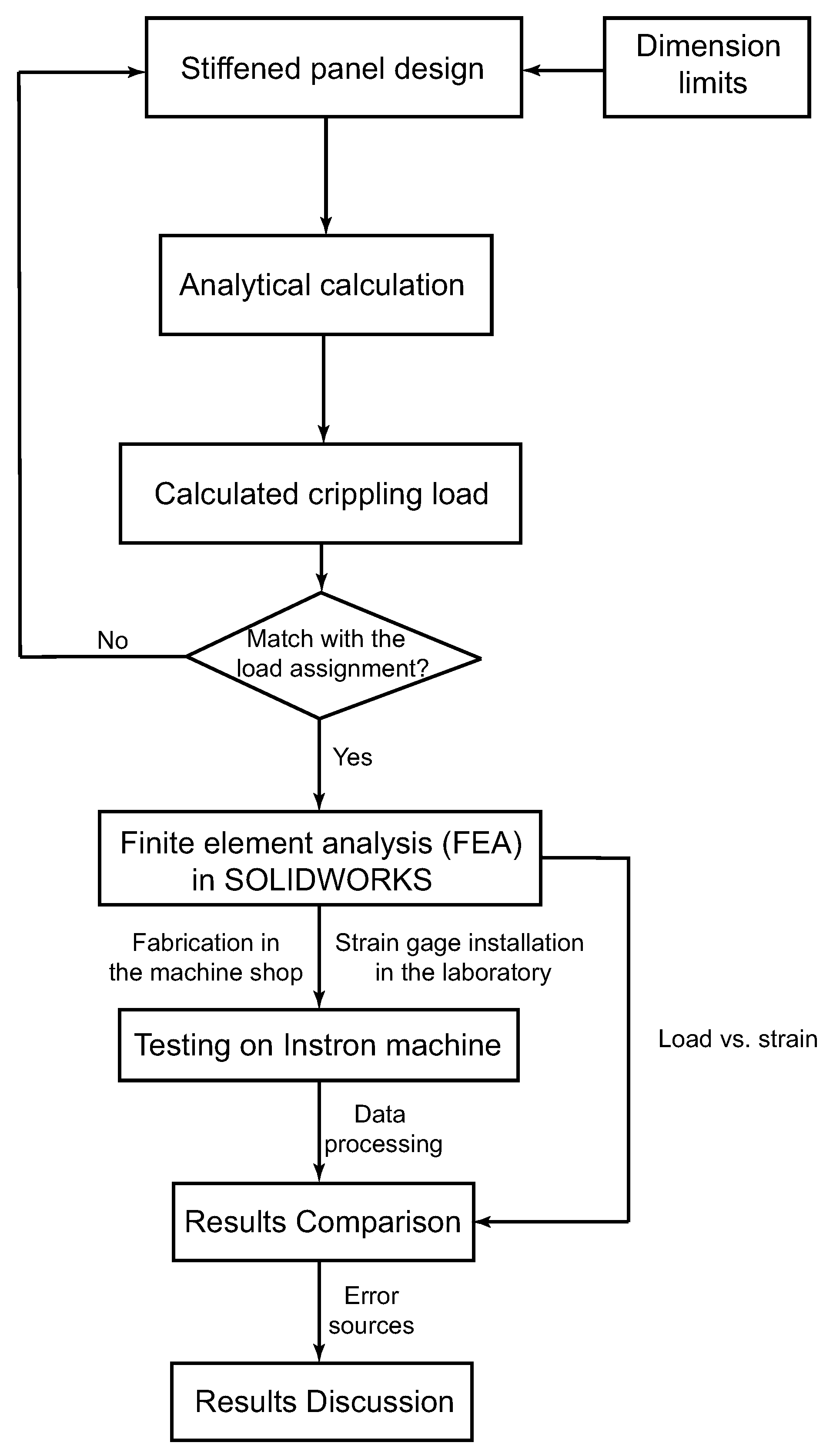
Figure 1 illustrates the student project process in MAE 372, a course focused on engineering design. As defined by ABET, engineering design is a systematic process for developing a system, component, or process that meets specific needs and specifications while adhering to given constraints. This process involves iterative and creative decision-making, applying principles of basic sciences, mathematics, and engineering to transform resources into effective solutions. For clarity, design constraints related to geometry are detailed in the Results section.
In this project, students are tasked with designing stiffened panels consisting of an aluminum sheet and L-shaped stiffeners, which are joined by rivets. While the sheet and stiffeners have fixed geometries, students determine the number and spacing of the L-shaped stiffeners and rivets to ensure the panels can withstand a crippling load specified by the lab instructors. Using the Needham and Gerard method for calculating crippling loads, students start with an initial estimate and adjust their design iteratively. If the calculated crippling load does not match the assigned value, students refine the design by modifying the spacing and configuration until the required load capacity is achieved, incorporating an appropriate safety factor.
After finalizing the geometry of the stiffened panels, students perform FEA in SolidWorks to validate their designs. Once the analysis is complete, they obtain materials from the machine shop and fabricate their panels. Following fabrication, students apply the knowledge and skills gained from the first laboratory session to install a linear strain gauge on the specimen surface for strain measurement in the laboratory room. Finally, the panels are tested on an Instron tensile/compression testing machine, where load versus strain data is collected and compared with the FEA results.
3. New Laboratories
3.1. Stress in a Pressure Vessel
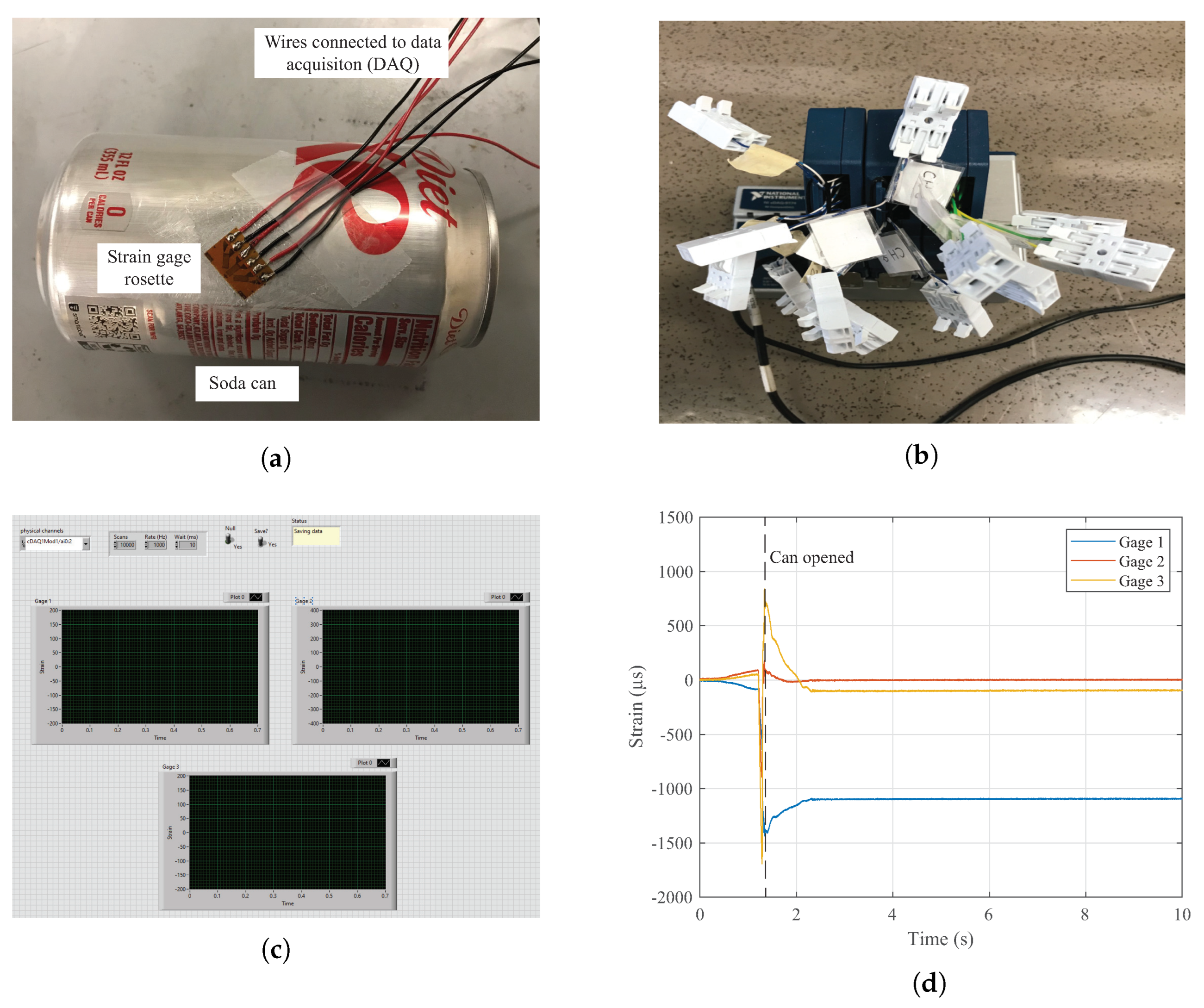
In the first laboratory session, each group receives an unopened soda can, a strain gauge rosette, and six strips of electric wire from the lab instructors. Following the provided tutorials, students learn how to install the strain gauge rosette on the soda can and solder six electric wires to the soldering terminals on the rosette. A successful example is shown in
Figure 2a.
To acquire strain data, a DAQ module and a LabVIEW program were developed, as illustrated in
Figure 2b,c, respectively. The DAQ system employs an NI compactDAQ system (cDAQ) 9174 chassis equipped with three NI 9237 modules, providing 12 channels for strain data acquisition. Each channel is configured in a half-bridge configuration, with a dummy resistor of 120
, as detailed in the NI 9237 manual [
14]. Quick connections to strain gauges are made possible via wire connectors on each channel. For the strain gauge rosette, three channels are utilized. Compared to traditional strain indicators, where three wires are required for each strain gauge, this laboratory setup reduces the wiring needs by saving three wires per rosette. Additionally, the NI DAQ module automates and simplifies strain data acquisition, enabling more efficient and repeatable measurements.
Sample strain data for the students’ laboratory reports is presented in
Figure 2d. The peaks correspond to strain values recorded as the soda can was opened. Using strain analysis and applying pressure vessel theory, the internal pressure of the can was determined to be approximately 10 psig, a reasonable result.
For potential users, part information and associated costs are summarized in
Table 2. It is worth noting that because MAE 372 and MAE 305 share the same laboratory space, it is challenging to track the usage of strain gauge installation materials, such as sandpaper, electric wire, and solder. Additionally, soldering tools and LabVIEW licensing are assumed to be readily available. Since the NI DAQ module is utilized across all laboratories, including the student project, its information is listed only once here.
3.2. I-Beam Under Bending Load
The wing spar, a primary load-bearing component of an aircraft wing, is traditionally constructed as a differential structure in the shape of an I-beam. One significant load on the spar is bending, caused by aerodynamic forces acting on the wing. To simulate this loading condition experimentally, a cantilever aluminum I-beam is subjected to weights applied at its tip. A portable structural testing apparatus was developed as part of a laboratory redesign, integrating three laboratories, including the one described here (see
Figure 3a). To avoid redundancy,
Table 3 summarizes the components and associated costs for the entire apparatus. Potential users may adapt
Table 3 to reflect their specific laboratory requirements. The apparatus was fabricated by the machine shop in the MAE department, and therefore, manpower costs are not included. Additionally, the costs for supplies and wires required for strain gauge and rosette installation, as well as part welding, are excluded.
A custom LabVIEW code designed for this laboratory is illustrated in
Figure 3b. The code utilizes seven channels of the DAQ module (
Figure 2b) to acquire strain data from a strain gauge rosette and four linear strain gauges attached to the mid-span surfaces of the I-beam. To generate a bending moment, standard weights are placed at the free end of the I-beam. Sample results are presented in
Figure 3c, demonstrating good agreement between experimental and theoretical predictions. It should be noted that all strain gauges and rosettes were installed by the author, who has not received formal professional training in strain gauge installation.
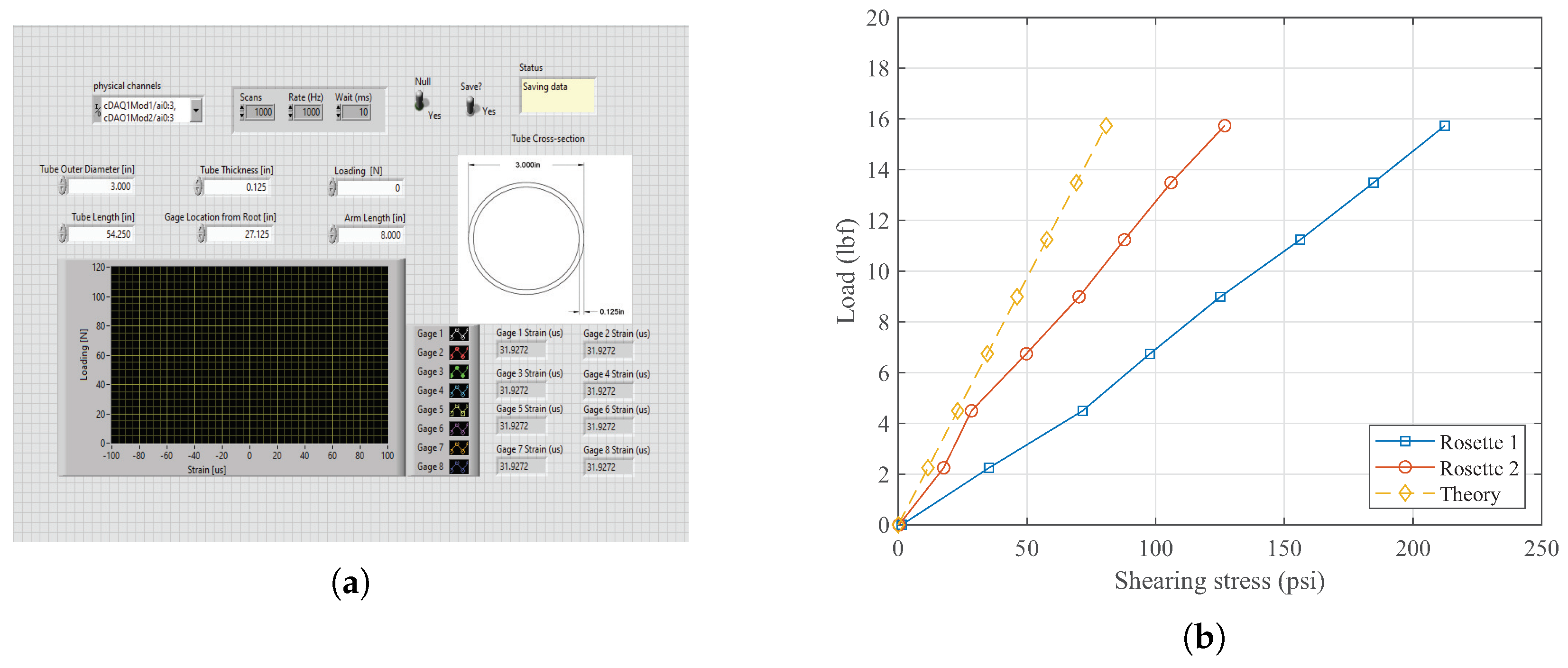
3.3. Hollow Shaft Under Torsional Load
In an aircraft, the fuselage behaves as a hollow shaft subjected to torsional load due to the aerodynamic forces acting on the vertical stabilizer. To replicate this scenario in the experiment, a long hollow aluminum shaft is used. Torsion occurs when an object twists around its longitudinal axis as a result of an applied torque. This laboratory experiment is conducted using the newly developed test apparatus shown in
Figure 3a. A total of eight DAQ channels are employed for strain data acquisition from two strain gage rosettes and two linear strain gages, all symmetrically installed on the outer surface of the hollow aluminum shaft.
Figure 4 displays the LabVIEW code for strain acquisition and some sample results, respectively. As shown in
Figure 4b, strain gage rosette 2 (whose structure is depicted in
Figure 2a) exhibits a larger percentage of error compared to strain gage rosette 1, due to misalignment during installation. Furthermore, this type of strain gage rosette is unable to accurately capture shear stress, which encourages students to consider the sources of error in the measurements in their laboratory report discussions.
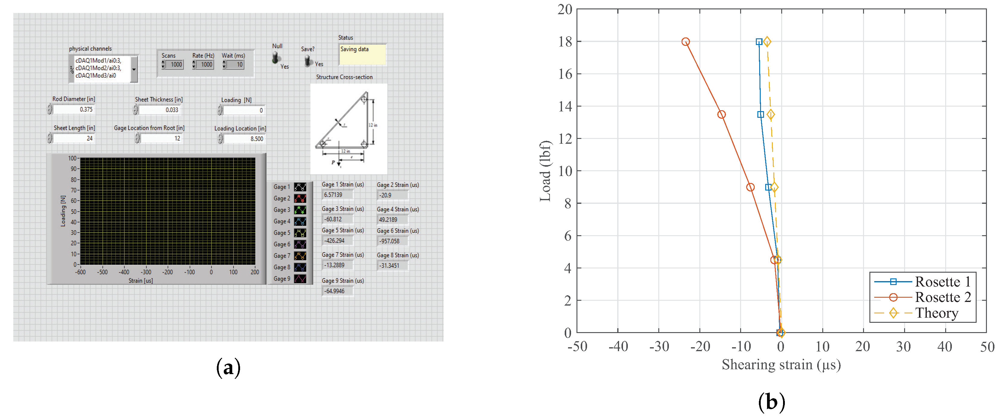
3.4. Shear Center on Thin-Walled Box Beam
Aerospace structures must not only withstand the applied loads but also remain lightweight. As a result, simple structural elements like beams are redesigned to maximize bending resistance while minimizing weight. This is achieved by redistributing material away from the neutral axis. However, this design makes the beam vulnerable to shear and torsional loads. The incorporation of shear webs significantly improves resistance to these loads. To study this structure experimentally, a thin-walled box beam with three stringers was designed using the newly developed test apparatus shown on the right side of
Figure 3a, which represents the final laboratory experiment conducted on this apparatus. Nine DAQ channels are used to acquire strain data from three strain gage rosettes installed on each aluminum sheet. Additionally, two digital deflection gauges attached to the bottom aluminum rods are employed to determine the shear center’s location when the load is placed on the bottom aluminum sheet. The shear center is the location where the two deflection gauges have the same readings.
Figure 5 presents the LabVIEW code for strain acquisition and some sample results. Theoretically, the shearing strain from strain gage rosettes 1 and 2 should be identical; however, strain gage rosette 2 on the bottom surface exhibits different behavior. Two potential improvements are suggested: one is using steel rods, and the other is reducing the structure’s length and switching to welded connections between the rods and sheets instead of bolted ones. When a load is applied to the bottom sheet, the surface bulges upwards due to the unsuccessful simulation of the rigid body.
3.5. Student Project
Stiffened panels are key subcomponents of wing and fuselage structures, often subjected to compressive loads. In many cases, the failure or crippling strength of short sections of flange-plate elements exceeds the local buckling stress. Consequently, the crippling strength is used as the design criterion for stiffened panels under compressive loads. After completing the analytical calculations based on reference [
15] and performing FEA in SOLIDWORKS, students finalize the geometry of their designed stiffened panels.
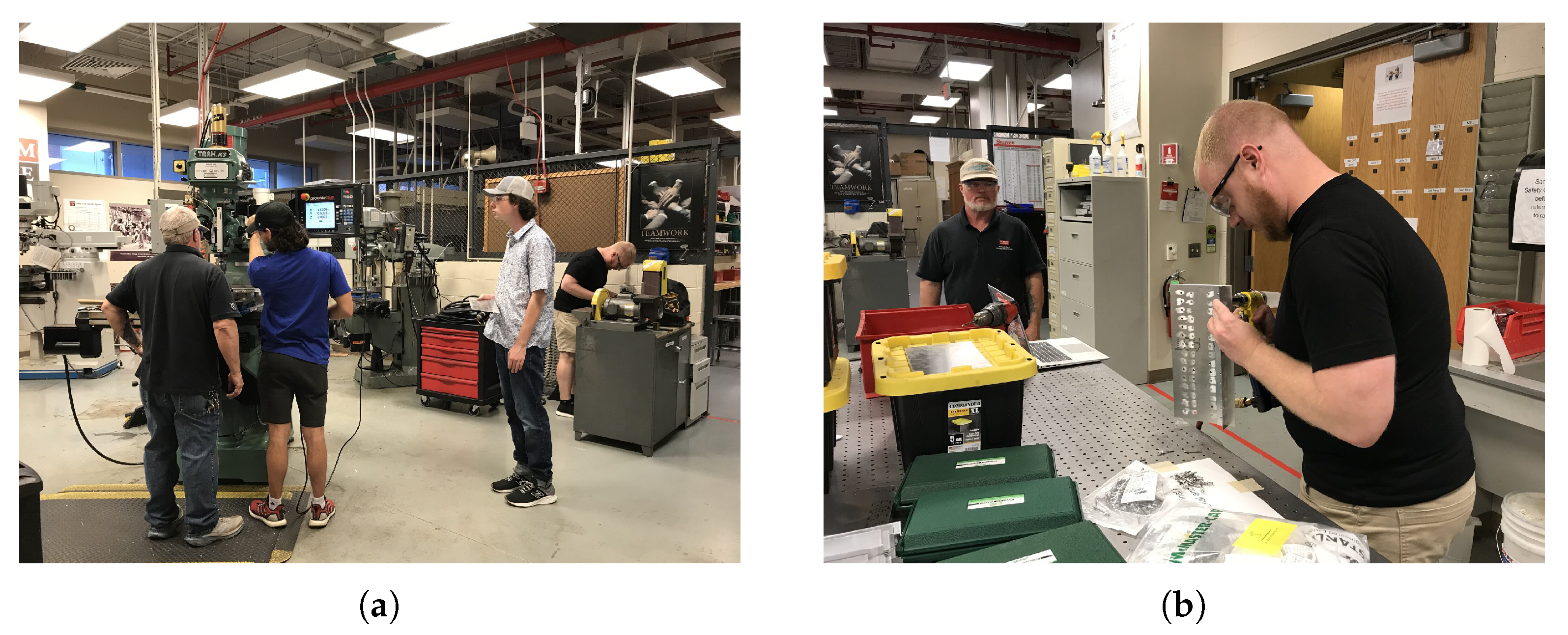
Using the finalized geometry, students drill holes into aluminum sheets and L-shaped stiffeners for rivet installation. After receiving basic training from the machine shop manager, they use a programmable drilling machine (
Figure 6a) to carry out the task. Once drilling is complete, students learn to install rivets for final assembly (
Figure 6b). With the assembly completed, students install a linear strain gauge on the back side of the specimen (
Figure 6c). For strain acquisition, the first channel of the DAQ module is used by all student groups, along with the LabVIEW code shown in
Figure 6d.
During the reserved testing time, lab instructors supervise students as they perform compression tests on their stiffened panels until crippling occurs, as shown in
Figure 6e.
Table 4 lists the materials required for the student project, along with their associated costs. The costs of the drilling machine, rivet installation tools, and the Instron tensile/compression testing machine are not included, as these resources are already available.
3.6. Discussion
The redesigned MAE 372 laboratory course seamlessly integrates traditional experimental setups with a comprehensive student project that addresses real-world design challenges, enriching the educational experience in aerospace structures. The course begins with hands-on activities, such as strain gage rosette installation, which closely align with the literature and provide foundational skills. The inclusion of a student project facilitates the application of theoretical knowledge to practical design and testing, an approach proven to enhance learning outcomes through active learning methodologies.
Students are introduced to various structural analysis techniques critical to aerospace structures, including stress and strain analysis in pressure vessels, bending loads on I-beams, and torsional loads in hollow shafts. The use of a single NI DAQ module, coupled with LabVIEW codes for strain measurements across multiple labs, ensures both cost efficiency and modernized data collection. Additionally, the newly developed test apparatus offers a cost-effective solution with accuracy comparable to theoretical predictions. The integration of FEA with practical testing—exemplified in the stiffened panel project—provides students with a comprehensive understanding of computational and experimental approaches in structural engineering.
Student feedback from course evaluation highlights the impact of the laboratory redesign:
Comment 1: “Lab was very helpful, aligned well with Structures class work.”
Comment 2: “I had a lot of fun with the final project. It taught me more in one week than I have learned in the entirety of aerospace structures the class.”
Despite these advancements, certain challenges remain. For instance, improvements are needed in the shear center experiment involving thin-walled box beams. Moreover, the adoption of emerging technologies, such as soft robotics and digital image correlation (DIC) techniques, presents exciting opportunities for further enhancing the laboratory experience.
3.7. Conclusions
The redesigned MAE 372 laboratory has demonstrated its effectiveness in enhancing student engagement and understanding of key structural concepts. By combining a hands-on student project with traditional demonstrations, the course bridges the gap between theoretical knowledge and practical application. The incorporation of a portable test apparatus and a streamlined data acquisition system not only ensures cost efficiency but also maintains a level of educational accuracy. This approach serves as a scalable model for other engineering programs aiming to modernize their laboratory curricula and illustrates how active learning strategies can be successfully integrated into aerospace education.
Future iterations could benefit from refining the test apparatus further and incorporating advanced techniques and emerging technologies. In the long term, the potential coexistence of physical and virtual labs represents a promising direction in engineering education, aligning with the growing trend of virtualization.


