Review

Radiation-Induced Effects on Semiconductor Devices: A Brief Review on Single-Event Effects, Their Dynamics, and Reliability Impacts

by
Vitor A. P. Aguiar
*,†,
Saulo G. Alberton
*,† and
Matheus S. Pereira
Institute of Physics, University of Sao Paulo-Rua do Matão, Sao Paulo 1387, Brazil
*
Authors to whom correspondence should be addressed.
These authors contributed equally to this work.
Chips 2025, 4(1), 12; https://doi.org/10.3390/chips4010012
Submission received: 11 February 2025 / Revised: 12 March 2025 / Accepted: 14 March 2025 / Published: 18 March 2025

Abstract

:
Radiation effects on electronic devices represent a major concern in applications for harsh environments, such as aerospace and nuclear facilities. This article presents a review of fundamental aspects of radiation effects on semiconductors, with a primary focus on Single-Event Effects. It discusses charge collection models, destructive effects, applications in detectors, and impacts on digital devices, drawing from recent research findings.

1. Introduction

The interaction of radiation with a material can deposit a certain amount of energy, which, depending on the type of material, may generate ionization within the medium. In the case of a semiconductor, the deposited energy leads to the creation of charge carriers that, in the presence of an electric field, can manifest as a current pulse at a measurement terminal. Indeed, since the 1950s, it has been observed that ionizing radiation was a significant cause of failures in semiconductor devices, which attracted the interest of technology companies such as IBM, Intel, and Texas Instruments [1].
By the 1960s, it has been already observed that electronics on satellites were not immune to failures, and numerous studies were conducted to determine the influence of cosmic radiation on electronic devices. It was observed that both particles from the Sun and extragalactic sources (including protons, neutrons, alpha particles, sub-nuclear particles, and heavy ions) could cause electronic devices to fail, either through direct interactions or nuclear reactions. Over time, it was also observed that failures occurred in terrestrial devices and in commercial aviation; these effects were due to contamination by alpha-emitting isotopes in the encapsulation of devices [1,2], as well as the interaction of cosmic rays with the Earth’s atmosphere, creating particle showers that include protons, neutrons, and even pions and muons [3,4,5,6], all capable of generating radiation effects on electronic devices.
The constant development of new materials and manufacturing technologies [7,8], which makes basic components smaller and more numerous, ensures that the study of radiation effects on electronic devices remains a hot topic. This is because certain technologies may be more resistant to some effects but more susceptible to others [2,9,10]. In the case of low-cost and/or easily maintainable systems, the common practice is to replace devices that exhibit radiation-induced failures. However, for electronics embedded in satellites, for example, it is crucial to ensure extended operational time without failures that could compromise the system. Systems that require high reliability must also be designed to minimize such failures.
In addition to designing devices with specific characteristics for use in radiation environments, there is increasing interest in using commercial-off-the-shelf (COTS) devices because of their low cost and high availability, although these devices require prior radiation-tolerance characterization.
The effects of radiation on electronic devices are typically divided into three main classes: total ionizing dose (TID), displacement damage (DD), and Single-Event Effects (SEEs). While TID and DD are cumulative effects, meaning that they do not manifest until a certain amount of radiation has hit the device, Single-Event Effects are stochastic in nature and even a single particle can cause a catastrophic failure. Although separated in classification, with studies usually being conducted to analyze each effect separately, in typical radiation-harsh environments, devices may be subject to all three classes of effects, which interfere with each other [11]. The interplay among these effects and their causes, both in well-established and new materials, is a topic of major importance [12,13,14,15].

2. Cumulative Effects: Total Ionizing Dose (TID) and Displacement Damage (DD)

The effects arising from the total ionizing dose on a device can be caused by all forms of ionizing radiation, directly or indirectly. For isolated TID studies, X-rays and gamma rays are usually employed. Electrons and protons are also generally used, although they can also generate the other types of effects, with lower probability.
Charges generated in the depletion region of a device usually undergo recombination or are collected by a terminal. However, in cases where the radiation interacts with an insulating region, such as the gate oxide of MOS-type devices, or a defect-rich region, the reduced mobility of carriers in this medium can result in charge accumulation.
The silicon dioxide used in semiconductors is generally amorphous. At the interface between the oxide and the doped crystalline silicon of the depletion region, the periodic interatomic potential of the lattice is disturbed, leading to the creation of potential traps. These traps may become accumulation centers for holes, as holes, due to their low mobility, cannot move sufficiently out of the oxide, while electrons can move relatively more easily under an electric field [16]. Figure 1 exhibits a schematic illustration of trapping in a MOS transistor. Although some recombination between electrons and holes does occur, there remains a residual accumulation of positively trapped charges in silicon dioxide, particularly in the interface region. This accumulation can be partially recovered by thermal treatment (annealing), whether induced or not. Radiation exposure during device operation amplifies this effect.
The effects of these trapped charges are diverse but can be summarized in the degradation of the electrical parameters of the devices: reduced transconductance, increased leakage currents through parasitic channels (leading to higher power consumption), reduced breakdown voltage, increased pink noise, changes in the device’s characteristic curve, and changes in the threshold voltage of transistors [17,18,19].
Displacement damage is caused by the non-ionizing component of energy loss (NIEL) from particles such as neutrons, recoil nuclei, heavy ions [20], protons, and high-energy electrons [21,22]. Non-ionizing atomic collisions lead to the displacement of atoms in the lattice, which can create various crystal defects, such as vacancies, Frenkel pairs, interstitial displacements, and others. Figure 2 illustrates some crystal defects that characterize displacement damage. These defects act as charge accumulation regions due to the trapping effect, modifying the electrical properties of the device [23,24]. Subjecting the device to a controlled temperature increase can anneal the crystal, minimizing undesirable effects.
Displacement damage mostly affects bipolar junction transistors (BJTs), charged-coupled devices (CCDs), and ultra-pure germanium detectors used in nuclear physics. In general, MOS-type devices are minimally affected by displacement damage [25].
Displacement damage studies can be conducted by using heavy-ion beams and, more commonly, neutron sources like D-T generators, fission reactors, and spallation facilities (spallation refers to the production of high-energy neutrons through the inelastic scattering of high-energy protons on heavy targets).
Displacement damage is also one of the main radiation effects in materials other than semiconductors, such as insulators, metals and alloys, thermal conductors, and ceramics [26,27,28,29].

3. Single-Event Effects

3.1. General Aspects and Test Methods

Single-Event Effects (SEEs) refer to the effects on electronic devices caused by the incidence of a single ionizing particle capable of generating a sufficiently large number of electron–hole pairs to disrupt normal system operation. Although, for a long time, it was thought that only heavy-ions and alpha particles were capable of causing SEEs, it is known that also muons, pions, neutrons, protons, and even electrons can cause SEEs [2,3,5,30,31,32,33]. The main reason for this is that technological advances make devices smaller and more densely packed, diminishing the tolerance to SEEs, as the involved capacitance and the required charges to cause state changes are smaller.
SEE testing can be conducted with neutrons [31] (which indirectly induce SEEs) in the same facilities used for displacement damage testing, lasers [34], and accelerators of protons, electrons, and heavy ions [1,5,35,36,37], as well as alpha-emitting or fissionable radioactive sources [38].
Laser experiments rely on generating a quantity of electron–hole pairs in the semiconductor similar to that generated by a heavy ion passing through the active layer of the device. In the single-photon absorption technique, a laser of energy greater than the bandgap of the material is used to produce a profile of energy deposition that is more intense at the surface and decays inward. The two-photon absorption technique is used for depth-resolved pulse analysis, using a pulsed laser with ultrashort pulses, luminosity of the order of 10 15 W / cm 2 , and an appropriate wavelength with energy lower than the bandgap of the material. This way, only in the focal point of the laser is the intensity of photons high enough to allow non-linear effects such as two-photon absorption to be important. Laser experiments simulate the results of heavy ions in a simpler and cheaper manner, allowing for even area scanning to identify sensitive regions. However, laser-induced charge generation is localized in a spot larger than the ionization track of a heavy ion, thus not corresponding to exactly the same phenomenon [34].
To test and qualify electronic devices, it is essential that the setup complies with the standards established by specialized technical organizations, such as the European Space Agency (ESA) [39,40], the American Society for Testing and Materials (ASTM) [38], and the Joint Electron Device Engineering Council (JEDEC) [41], where the characteristics of the beams and irradiation systems are outlined. Although adhering to these standards is not mandatory for academic studies, doing so allows for better inter-laboratory comparisons of the observed results.
Experiments to assess susceptibility to SEEs with heavy ions should ensure a uniform flux of particles on the device under test (DUT) that is sufficiently low to allow for the for the individual discrimination of independent events, while avoiding other types of damage to the device, such as excessively high doses that could cause TID effects or overheating. The main recommendations from these organizations are as follows:
  • Large beam spot to cover the entire area of interest or a microbeam with scanning capability. In the case of a large spot, it should be at least 90% uniform in the considered area.
  • Flux: The particle flux should fall within the range of 10 2 to 10 5 ions.cm−2.s−1. This requirement ensures that the device is not hit by more than one ion during a data acquisition cycle.
  • Range: The minimum beam penetration should be 30 µm in silicon. However, for several studies, it can be assumed that the range should simply be much greater than the thickness of the active layer [38].
  • Energy and LET: The energy and linear energy transfer (LET) (linear energy transfer is the amount of energy deposited in the device per unit path length) of the beam in the device must be known within a maximum variation of 10%. The LET depends on the particle energy and species and is generally calculated through computational simulations, using SRIM software [42], for example. To ensure that the LET does not vary by more than 10%, it must be guaranteed that the Bragg curve in the region where the charge is collected (the active layer) forms a plateau, a condition that is usually met when the range is much greater than the thickness of the active layer.
  • Beams: Tests should be performed with several beams, ideally some with the same LET, as the effects can vary with the ion species. If possible, data should be obtained up to twice the saturation LET.
Several laboratories and facilities worldwide meet, partially or completely, these requirements, and perform studies and qualification of devices regularly, such as SIRAD (LNL-Italy) [43,44,45], which can provide ions from the 15 MV tandem accelerator or the ALPI linac, the CNA (Spain) [46], where a microbeam is available for micro-characterization, and SAFIIRA (LAFN-Brazil) (Figure 3), which uses heavy-ions from the 8 MV Pelletron accelerator with a combination of defocusing and multiple scattering to achieve high uniformity and easily tunable intensity [47].
SEEs can be divided into two classes: non-destructive, which cause temporary interference or failures that can be corrected by restarting the system or cycle, and destructive, which render the device permanently inoperable.
Non-destructive SEEs:
  • Single-Event Transient—SET: A transient effect (voltage/current pulses) that propagates through the circuit and can trigger subsequent effects. Its correction is complex, as the transient effect generated in the device may only be detected at another point in the circuit. Newer technologies are more susceptible to SET because the critical charge is smaller.
  • Single-Event Upset—SEU: The generation of charge produces current/voltage spikes (SET) that affect the logic (on/off) of the device. In general, these effects can be summarized as a bit flipping from 0 to 1 or vice versa. These effects primarily affect digital devices. In cases where multiple bits are affected, this effect is called Multiple-Bit Upset (MBU) [48];
  • Single-Event Functional Interrupt—SEFI: A subclass of SEU related to high-density digital devices such as Field-Programmable Gate Arrays (FPGAs), as radiation can affect the logical system of the component.
Destructive SEEs:
  • Single-Event Latch-Up—SEL: A parasitic thyristor is activated in CMOS circuits by a high-LET particle, generating a high current flow and overheating, potentially destroying the device. Since the parasitic thyristor is activated in deep layers (below the source and drain channels), it is important that the particle deposits energy in this region.
  • Single-Event Burnout—SEB: Power devices in the “off” state can be activated by a particle capable of generating enough charge to burn out the device.
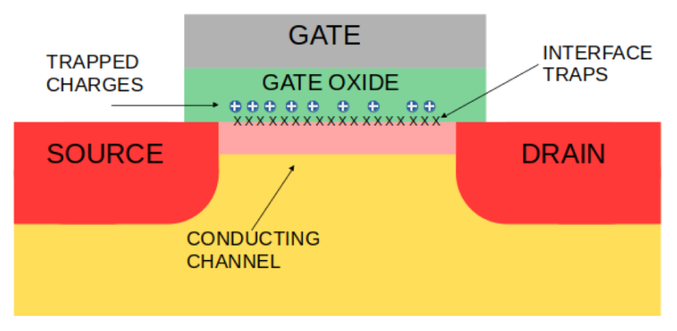
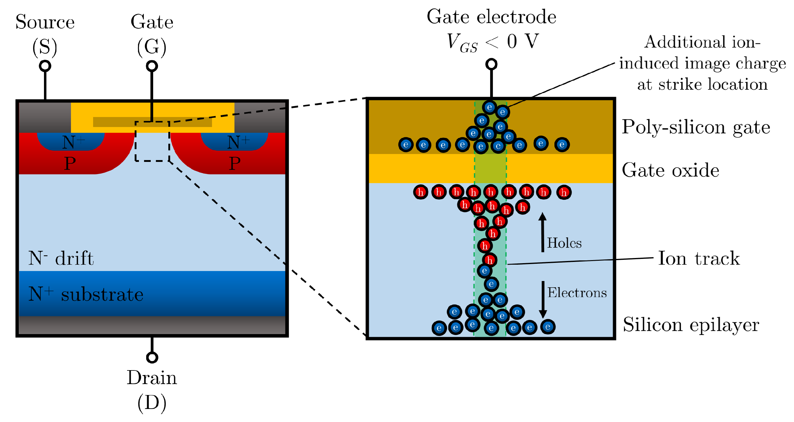
  • Single-Event Gate Rupture—SEGR: Primarily affects MOS power devices. The accumulation of charges at the Si/SiO2 interface increases the electric field in the gate oxide, permanently breaking its dielectric strength.

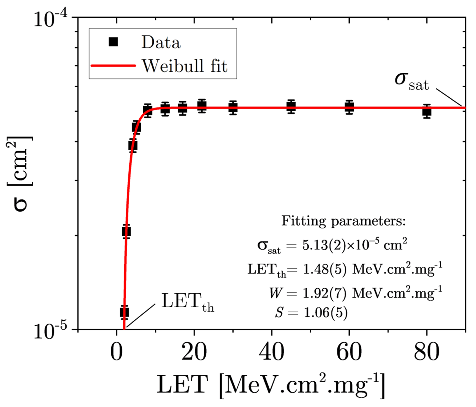
3.2. Cross-Section and Failure Rate

Given that a particle deposits energy and causes charge collection by a sensitive node of the device, the next step is to determine whether this charge collection leads to an observable event and, if so, with which probability.
The event cross-section represents the effective interaction area and can be understood as an indirect measure of the probability of event occurrence. The cross-section is calculated as
σ = N Φ
where N is the number of detected SEEs and Φ is the beam fluence accumulated during the test, in units of particles.cm−2. As a result, the cross-section is measured in units of area. In cases where the entire sensitive area exhibits effects, the saturation of the cross-section is reached, meaning that its value no longer increases, even if the incident LET and the corresponding deposited charge increases [5,21].
SEE characterization experiments on devices are typically conducted to measure the event cross-section as a function of parameters such as incident LET, applied voltage, incidence angle, mitigation techniques employed, and others. Describing the behavior of the cross-section as a function of the test parameter allows for comparisons between different devices with the minimum amount of information possible. In experiments where the cross-section is measured as a function of incident LET, it is common to obtain a data distribution like the one shown in Figure 4, where the data follow a cumulative Weibull distribution [49]:
σ ( LET ) = 0 , for 0 LET < LET t h , σ sat 1 e LET LET th W S , for LET LET t h .
where σ sat is the saturation cross-section; LET th is the threshold LET, which represents the minimum LET value capable of generating an observable SEE; and W and S are width and shape fitting parameters, respectively, which describe the curvature between the threshold and saturation regions. The modeling based on the Weibull curve implies that no events can be observed if the LET of the particle is below the threshold LET; this statement is not true and represents a limitation of the model, as subthreshold events can be caused mainly by secondary processes, or even direct ionization, if the particle fluence is high enough to ensure detection of the single event [50,51,52,53].
Some authors [52] criticize the use of the cumulative Weibull distribution for modeling, as the saturation cross-section obtained from the fit may not correspond to the reality if the data do not extend to the saturation region. Furthermore, the common practice in the community is to plot cross-section data on a logarithmic scale and LET values on a linear scale, which can obscure systematic errors much larger than statistical ones [52]. Incorrect values of the saturation cross-section can influence the calculation of the failure rate in operation, making it a significant concern for applications. The Weibull form of the cross-section curve can be explained by the small differences in sensitivity and charge production/transport between regions or cells in a device [54].
Energy deposition can only generate an observable effect when it occurs in a region where charge can be collected. This region is called the sensitive region of the device, and its shape influences error rate calculations for applications where particles can impact in any direction [52,54]. Among the models used to represent the sensitive (or active) region, the simplest is the Rectangular Parallelepiped (RPP) model, where the sensitive region is treated as a parallelepiped with a surface area equal to the saturation cross-section and a depth equal to the depletion region. In this approximation, the sensitive layer of the device can be modeled as a parallel-plate capacitor, where the capacitance C is expressed in terms of its dimensions and the permittivity of the medium [4,5,21]:
C = Q Δ V = ϵ m . A d = ϵ m . x y d
where Q is the collected charge, Δ V is the applied potential difference, ϵ m is the permittivity of the medium, d is the distance between the plates (where the voltage is applied), and A is the area of the plates, which can be expressed in terms of the sides x and y, assuming a rectangular-plate capacitor. The charge generated by the ion in the sensitive region of the device is calculated by the conversion of the deposited energy into electron–hole pairs, which depends on the semiconductor material, as shown in Table 1.
More advanced models that consider complex devices involve Monte Carlo simulations and a detailed description of charge generation and transport within the sensitive volume [54,55,56,57,58]. Among these models, the one by Murat and collaborators [59] is noteworthy, as it incorporates details of the structure and temporal evolution of the ionization track through Monte Carlo simulations, even demonstrating the importance of straggling in energy and the passivation/metalization layer in the observed effects.
There are also simplified models that assume that all charge collection occurs via diffusion, neglecting non-linear effects such as drift–funnel collection. These approaches [60,61] have the advantage of incorporating charge deposited outside the actual sensitive region of the device into the cross-section model, a consideration not included in models that ignore diffusion, which rely on the assumption of an unrealistic sensitive volume. Because these models do not accurately calculate the current pulse generated in an event, they were proposed mainly for use in CMOS devices. Among these models, one of the most recent and interesting ones is the one presented by Sogoyan and collaborators [61], where the cross-section curve is described by
σ = L π LET LET 0
where L and LET 0 are the only adjustable parameters of the model and L represents the effective distance between two CMOS cells. This advantage in the number of variables comes at the cost of its limitation to LET values sufficiently above the threshold LET, as in the low-LET regime, the model lacks accuracy because of non-linear effects, such as ionization from reaction by-products. In general, the authors recommend it for deep-well technologies and data that can be linearized in the special coordinates l n ( L E T ) , σ .
The primary goal of modeling the SEE cross-section of a DUT is to predict its failure rates during operation in a specific radiation environment. In general, heavy ions are the primary contributors to SEEs in space [52], whereas cosmic ray-induced neutrons are the main cause of SEEs at flight altitudes and ground level on Earth [62,63]. For instance, for space applications, the Single-Event Rate (SER) can be determined by integrating the SEE cross-section over all LET values of particles in the outer-space environment:
SER = Ω 4 π σ ( LET ) d ϕ ( LET ) d LET d LET ,
where Ω is the solid angle subtended by the device relative to the omnidirectional radiation fluence rate ϕ and d ϕ / d LET is the differential LET spectrum of heavy ions in space. Similarly, for atmospheric applications, the SEE cross-section can be assumed to depend continuously on the energy E of atmospheric neutrons. In this case, by considering Ω = 4 π for simplicity, the SER can be estimated as [64]
SER = σ SEE ( E ) d ϕ ( E ) d E d E ,
where d ϕ / d E is the differential energy spectrum of atmospheric neutrons. Although the SER is expressed in s−1 units in the SI, it is conventionally expressed in units of Failures-in-Time (FIT), where 1 FIT is equivalent to 1 failure per 10 9 device-h of operation.

3.3. Single-Event-Transients: Charge Injection and Collection

In silicon, a particle with an LET of 1 MeV.µm−1 will generate 2.8 × 10 5 electron–hole pairs per µm, which corresponds to a charge density of ±44.5 fC.µm−1. Particles with higher LET values will generate a higher number of pairs. In addition to the primary ionization caused by the incident ion, there is also a cascade of secondary ionization caused by the electrons from the primary ionization, which have enough energy to induce further ionization. This structure is referred to as the particle’s ionization track, and in semiconductor materials like silicon, its duration is of the order of picoseconds [65,66]. In this region, the high concentration of electron–hole pairs, much higher than the typical doping level in semiconductors, exhibits collective behavior that modifies the external electric field. This condition is known as electron–hole plasma. The structure of this region of the track, which expands radially over time through ambipolar diffusion, and whose longitudinal carrier density depends on the local LET of the incident particle [65,66,67], alters the electric field and influences charge transport and collection.
In the absence of an electric field, only diffusion and recombination phenomena occur between electrons and holes, so any current pulse signal in a diagnostic system would be attributed to carrier diffusion. In an operating device (whether a detector or an electronic device), where an electric field is present in the depletion region, electrons and holes are separated within this region, and charge collection occurs through drift.
One of the earliest models for charge collection describes the transient pulse as a result of changes in the minority carrier distribution in the depletion layer, caused by the creation of electron–hole pairs, which leads to their neutralization (collapse). The applied electric field extends through the center of the ionization track, which remains nearly neutral in charge. The electric field penetrating along the ionization track is responsible for the separation of electrons and holes, transporting charges from the initially neutral region to the depletion region [66,68]. This scenario is known as the “funnel” effect, which dissipates when the carrier concentration in the depletion region reaches a level that restores the conditions prior to the interaction [66], and the remaining carriers will diffuse through the semiconductor [4,5]. The current pulse in the semiconductor is thus generated by a combination of direct contributions (drift collection and funnel effects) and diffusion. Figure 5 illustrates the three charge collection processes, and Figure 6 illustrates the pulse shape, which depends on the device in question and the number of independent sensitive areas present in the device [69].
In the funnel model, the collected charge due to the drift and funnel effects is defined as
Q c = q w x = 0 L e f f d E ( x ) d x d x = q x = 0 L e f f N 0 ¯ ( x ) d x ,
where q is the elementary charge, w is the energy required to create an electron–hole pair, L e f f is the effective length of the charge collection region (i.e., the length of the funnel and depletion region along the particle’s trajectory), d E ( x ) d x is the stopping power of the particle in the medium, and N 0 ¯ is the density of electron–hole pairs along the track (these definitions assume that LET is numerically equal to the stopping power, which may not hold if delta electrons of sufficiently high energy are considered) [66,67,70]. Thus, the collected charge depends on the funnel length, which lacks an analytical expression, and various semi-empirical models used by many authors, which are not always equivalent [70]. The description of the funnel typically depends on arbitrary constants fitted to experimental data and aims to capture the behavior of the electric field under out-of-equilibrium conditions. However, the main limitation of this model lies in its description of the electric field along the ionization track, as the collapse of the depletion region and the modification of the electric field are not satisfactorily explained.
According to Hu et al., the length of the funnel can be expressed solely as a function of the device parameters, thus making it independent of the incident particle [70,71]:
L f = 1 + μ n μ p W D cos θ ,
where μ n and μ p are the mobilities of electrons and holes, respectively; W D is the length of the depletion region; and θ is the angle of incidence of the particle. Takada et al. later extended the model including the incidence angle of the particle and the width of the depletion region, fitting data from medium–high-energy protons and alpha particles [72].
In the more complex model by Oldham et al. [65,66,70] (Equation (9)), which takes into account the electron–hole plasma lifetime τ C (Equation (10)), the funnel length also depends on the applied depletion voltage V 0 , the carrier density at the beginning of the ionization track N 0 , the doping concentration N A , the average hole velocity v P , the ambipolar diffusion coefficient D, and a factor K (calibrated with experimental data) that represents the shielding of the electric field caused by electron–hole pairs. This factor is especially important when analyzing data obtained with ions that penetrate the device to a depth of less than 14 µm [66]. Total charge collection includes also the amount collected by diffusion.
L f = μ n V 0 exp ( K N 0 ) τ C = μ n V 0 exp ( K N 0 ) 3 N 0 8 π N A v P D 1 / 3
τ c = 3 N 0 8 π N A v P D 3 / 2
The dependence on the energy and atomic number (Z) of the incoming particle arises from the carrier density at the track in this model. A recent work by Aguiar and collaborators [73] has analyzed both the Oldham and Hu models with an extensive set of experimental data, obtaining a new value for the shielding parameter compared with the previously reported ones. The work shows that although the model by Oldham et al. does provide a better fit to the data, the Hu model cannot be completely discarded by statistical analysis.
To understand charge transport processes, it is important to distinguish between low- and high-injection conditions. These two conditions differ in the amount of charge carriers generated in comparison with their equilibrium concentration. Let M 0 and m 0 represent the equilibrium concentrations of the majority and minority carriers, respectively. The injection level is considered low when the following conditions hold:
  • M i M 0 .
  • Δ m = | m i m 0 | M 0 .
That is, the minority carrier concentration must remain much smaller than the majority carrier concentration, which should not undergo significant change. In the specific case of low-level injection, the solution is analytical and can be found in textbooks. However, when this condition is not satisfied, the charge transport processes change, which can lead to effects such as anomalous diffusion, the breakdown of the linearity of the recombination rate, changes in carrier mobility, variations in the electric field, etc., which affect the response of the device.
A more recent alternative model by Edmonds et al. [74,75,76,77,78] is the ambipolar diffusion with a cut-off (ADC) model, an analytical model based on drift and diffusion equations under high-injection conditions. This model offers a different perspective on the electrodynamic behavior of semiconductors during interactions, in contrast to the funnel model. It assumes that charge generation inside the semiconductor is localized, stationary, and sufficient to satisfy high-injection conditions, where the minority carrier concentration exceeds the equilibrium concentration of majority carriers. The collected charge is calculated based on diffusion and then scaled by a factor that accounts for drift effects. The cut-off is applied when the collected charge exceeds the generated charge. The physical reasoning divides the semiconductor into two regions (Figure 7): a depletion region, where an electric field transports carriers via drift, and a quasi-neutral region (QNR), where the charge imbalance is smaller than the majority carrier concentration but still significant enough to perturb the fields in the medium. The QNR is further divided into an ambipolar diffusion (AD) region, where most generated carriers reside and which has high conductivity due to the large carrier concentration, and a high-resistance region (HRR), where the carrier concentration is low, leading to low conductivity. A potential difference exists between the contacts in the depletion region and the substrate beneath the HRR. A weak field develops in the AD region due to its high conductivity, while a strong field forms in the HRR due to low conductivity. This high field in the HRR prevents minority carriers from entering it while allowing majority carriers to be collected at the contact. In the AD region, diffusion is the dominant transport mechanism. Since minority carriers cannot enter the HRR, diffusion occurs only toward the depletion region boundary (DRB), where they are collected. The collected charge at the depletion region contact is given by [74,77]
Q = 1 + D m D M q Q N R Ω ( x ) g ( x ) d 3 x ,
where D m , M are the diffusion coefficients for minority and majority carriers, respectively; q is the elementary charge; g ( x ) is the density of electron–hole pairs as a function of spatial coordinates; and Ω ( x ) is a function representing the relative importance of each charge position in the collection process. The main challenge of this model is determining the form of Ω ( x ) , which depends on the boundary conditions for each situation.
The ADC model has been extended to multi-junction situations [76], and its validity has been tested in technology computer-aided design (TCAD) simulations. The model has also been applied to transient and linear charge generation scenarios, although the transient scenario has only been solved in terms of the total collected charge without considering the temporal distribution of the collected charge. This temporal aspect is critical to the development of radiation detectors and to understanding device switching tolerance. Applications to semiconductor device irradiation [77,78] have shown good agreement with experimental data, although the determination of Ω ( x ) was based on low-injection data, solved either analytically by using the Laplace equation [77] or with TCAD simulations [78].
A comprehensive description of the phenomena involved is complex and depends on the doping profile and device structure [79,80], the LET of the incident particle at each point along the trajectory, the spatial and temporal structure of the ionization track [81], and the solution of the resulting Poisson and continuity equations over time. Liu et al. [67] used GEANT4 to model the interaction, demonstrating that the radial and longitudinal variations in LET along the ionization track cannot be ignored:
  • High-energy ions (>8.0 MeV/u) in large tech node devices: LET can be considered constant and equal to the value at the surface;
  • High-energy ions (>8.0 MeV/u) in small tech node devices: radial LET variation should be considered;
  • Low-energy ions (<0.3 MeV/u) in large tech node devices: longitudinal LET variation should be considered;
  • Low-energy ions (<0.3 MeV/u) in small tech node devices: both longitudinal and radial LET variations should be considered.
An accurate description of the charge collection region is crucial to understanding charge collection efficiency (CCE), which represents the fraction of the generated charge that is measured. CCE also depends on the particle’s range in the medium, the mobility of carriers, and their diffusion length [82,83]. In addition, the lifetime of the charge collection condition plays a dual role, determining both the amount of charge collected and the transient response time observed. Analyzing the system from the CCE perspective highlights the importance of understanding these phenomena for particle and radiation detectors. From the perspective of electronics, the intensity and duration of transients in devices can significantly impact their failure conditions [84].

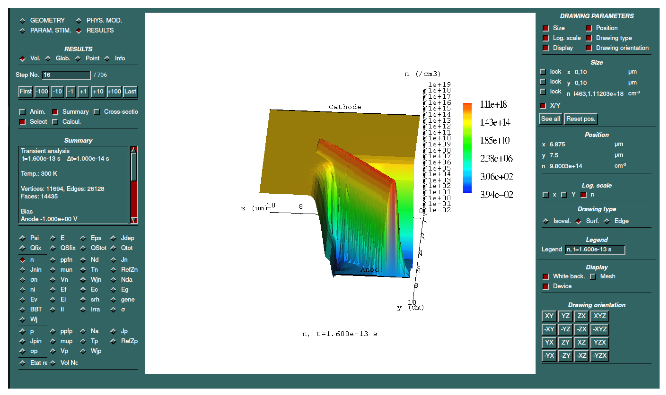
3.4. Simulations and Computational Methods

The understanding of the effects of radiation in semiconductor devices is composed by the knowledge of the interactions of radiation in the matter and how the effects of these interactions propagate over time and position inside the device.
In the context of stopping power of ions in matter, the software package SRIM (Stopping and Range of Ions in Matter) is one of the most utilized for accurate calculations of stopping power and ion range in matter. The quantum collision formalism adopted in SRIM is applicable to all ion-target combinations and allows for the definition of arbitrary incidence directions on planar targets. SRIM comprises a collection of computational packages and performs ion stopping calculations for energies of up to 2 GeV / u in elemental targets, composite materials, mixtures, and gases arranged in up to eight layers.
SRIM also includes the embedded computational program TRIM (Transport of Ions in Matter), based on the Monte Carlo method, which provides the most comprehensive and accurate calculation approach. In addition to employing the universal interatomic potential, the high computational efficiency of TRIM is based on two major approximations [42]: (i) Biersack’s Magic Formula, which enables a quick and precise solution of the scattering integral, and (ii) the concept of Free Flight Path, allowing only significant collisions to be evaluated. Nevertheless, if desired, the user can disable these approximations for extensive calculations.
TRIM enables detailed calculations of the three-dimensional distribution of trajectories and energy losses of ion and recoil, atomic recoil cascades in the stopping target, angular and energy straggling, and other associated kinetic phenomena: damage and vacancy production in the target, reflection, transmission, sputtering, ion implantation, ionization, and phonon production, among others. The accuracy of SRIM has been compared on more than 28,000 experimental data points extracted from over 2,300 references [42]. For this dataset, the SRIM-2010 version achieved an overall accuracy of 4.3% [85]. SRIM exhibits better than 10% accuracy for approximately 85% of these experimental data points [85]. Figure 8 illustrates the energy deposition profile for 56Fe at 400 MeV impinging on silicon.
Given the stochastic nature of radiation interactions with matter, Monte Carlo-based computational simulations are valuable tools for studying radiation effects. The Geant4 libraries [86] likely represent the most widely used general-purpose toolkit, offering integrated functionalities for physical models, hit detection, tracking, and geometry. Frameworks based on Geant4, such as G4SEE [87], have been specifically developed for SEE studies.
Technology computer-aided design (TCAD) tools use computer simulations to develop, optimize, and analyze semiconductor devices and manufacturing processes and are the principal tools to understand the behavior of electronic devices under radiation. With specialized software like Synopsys Sentaurus [88] and Silvaco Atlas [89], it is possible to simulate the electrical, thermal, and mechanical properties of semiconductor devices, reducing the need for costly and time-consuming physical prototypes. To use TCAD simulations, it is necessary to define the device structure and material properties, followed by setting simulation parameters, defining the precision, and selecting the relevant physical models for the specific device. Both Sentaurus and Atlas can simulate radiation effects, including Single-Event Effects like Single-Event Upset (SEU) and Single-Event Transient (SET), as well as total ionizing dose (TID) effects. ECORCE (Étude du Comportement sous Radiation des Composants Électroniques) is another promising TCAD tool focused on simulating radiation effects on electronic devices, making it an excellent resource for analyzing and comparing the reliability of components under radiation exposure [90]. The software tool is based on the finite volume method, solving equations of the drift–diffusion model coupled with the heat equation on a dynamic mesh, with adaptive refinement and the updating of the simulation grid, which reduces computational time without compromising precision. Figure 9 reproduces a screen of the program, showing results and configuration parameters [90]. However, it is important to note that the ion track is usually described by TCAD software applications as a density of charge carriers with a Gaussian-like profile [90,91,92], which is an approximation not always accurate, as described before.
There are several other TCAD packages available, both commercial and open-source, but the details would require a dedicated review. The website TCAD Central [93] lists several of these packages, their main characteristics, and several materials for reference.

3.5. Particle Detectors and Systems for Nuclear and Particle Physics

The operation principle of semiconductor particle detectors is based on ionization by single particles, so Single-Event Transients are expected and desired. The charge carriers generated by an ionizing event can be collected in the sensitive volume of the semiconductor, thus giving rise to a current peak in the electronic system which can be acquired as an indirect measurement of the energy of the particle [5]. In the case of photons, its detection is based on the same principles, with the current peak being caused by photoelectric, Compton, or pair production effects. Although photons can also generate single events in semiconductor devices as a result of photoelectron production [94], its impact is negligible, compared with heavy-ions, at X-ray and gamma-ray photon energies; in addition, X-ray and gamma-ray photon detectors usually require large semiconductor volumes compared with typical electronic device die volumes, as the interaction probability is much lower than that of charged particles.
The simplest design for a semiconductor detector is the junction diode based on P-N or metal–semiconductor (Schottky) junctions. In these junctions, the equalization of Fermi levels creates charge diffusion, leading to an electric field opposing the diffusion until equilibrium is reached, and the field acts as a directional barrier to charge transport (diode) [95,96]. Due to the high carrier density in metals, Schottky junctions are analogous to abrupt p n junctions. This region of unbalanced charges is called the depletion layer and can be increased applying a reverse bias V a , defining an effective detection volume based on the given acceptor ( N a ) and donor ( N d ) doping concentrations. In the one-sided abrupt junction approximation, for simplicity, the width of the depletion layer W d can be estimated as [95,96]
W d 2 ϵ q N · ( V a + V b i ) ,
where ϵ is the permittivity of the semiconductor, q is the electron charge, V b i is the built-in voltage, and N is the doping concentration of the lightly doped region, either N d or N a for p + n or n + p junctions, respectively. According to Equation (12), thick detectors can be achieved with low-doping concentrations, resulting in a high-resistivity material. However, even in the highest-purity typical semiconductors for detectors, i.e., silicon and germanium, residual impurities still act as either p-type or n-type dopants (usually of the order of 10 9 / cm 3 [97,98]).
The techniques used in the semiconductor industry to create micro-devices can also be applied to the production of semiconductor detectors. By using photolithography and ion implantation, it is possible to selectively dope portions of the starting bulk material, creating segmented doped strips on the wafer, and then each strip can independently detect particles, which improves positional sensitivity. Further segmentation can be applied to divide the strips into smaller regions, as seen in pixel detectors, thus enhancing positional resolution even more. A comprehensive review on silicon detectors is found in [99].
For these devices, each strip or pixel must be coupled with an independent readout circuit, which increases the complexity associated with the technology. To overcome this problem, hybrid pixel detectors were developed by using integrated circuit technology, coupling the readout with pixels within the same bulk material, in a few millimeters, usually using the complementary metal–oxide semiconductor (CMOS) process [100]. This reduces both the size and the external complexity of the system. This configuration is called Monolithic Active Pixel Sensors (MAPSs) and is commonly used in high-energy, high-intensity experiments. In these cases, both the detector and the readout electronics must be radiation-hard, as exposure to high doses might compromise the results obtained or shorten the lifetime of the system [101].
Silicon is still the most widely used material for detectors because it is cost-effective and integrates well into electronic systems. Germanium is another common option, and due to its higher density, it is well suited for high-energy gamma-ray and X-ray detection. Some compound semiconductors, like gallium arsenide (GaAs), cadmium–zinc telluride (CZT) and silicon carbide (SiC), are used in specialized applications, such as high-energy radiation detection and harsh environments, due to their superior radiation hardness and high electron mobility [95]. GaAs devices have gained interest in recent years, particularly in low-energy X-ray and γ ray detection [102,103,104,105], although their application for charged particle detection was only briefly studied for protons and alpha particles [106,107]. Silicon carbide detectors, on the other hand, are the first choice for several applications that require high radiation hardness [108,109,110,111]. Other materials, such as Ga 2 O 3 [112], diamond [113], and perovskites [114,115,116], are also promising for radiation detection in harsh environments.

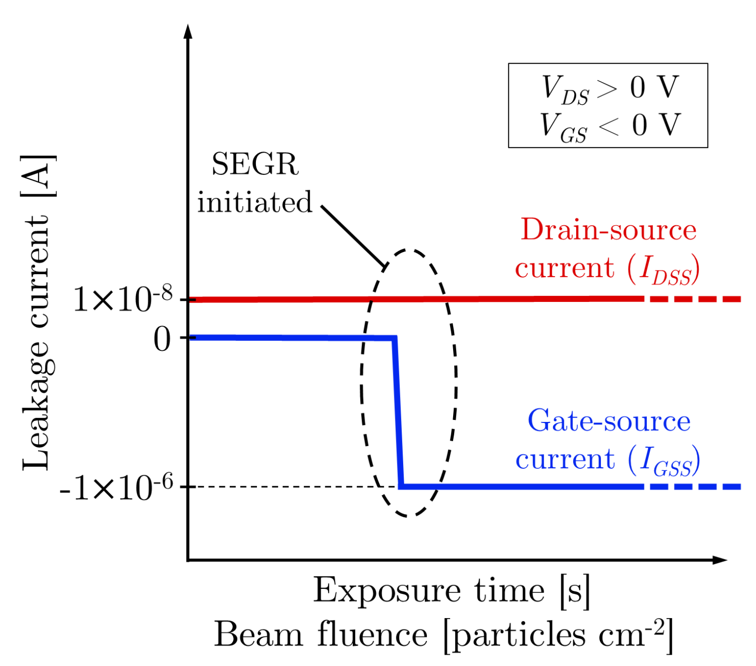
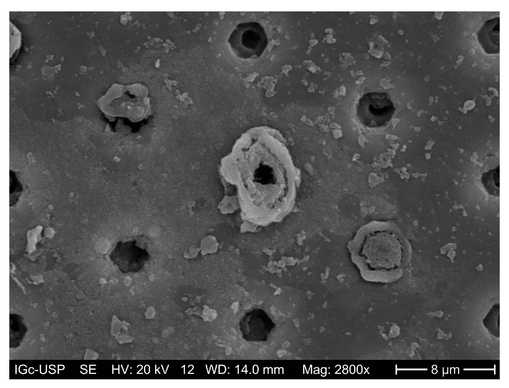
3.6. Destructive Effects: Single-Event Gate Rupture and Single-Event Burnout

Unlike non-destructive SEEs (soft errors), destructive radiation effects (hard errors) cause irreparable and permanent damage, potentially compromising critical applications like space missions. Permanent radiation damage in electronic devices was first reported by Pickel and Blandford in 1980 [117]. In the mid-1980s, the research on destructive radiation effects intensified [118,119,120,121,122].
In destructive SEEs, a single energetic particle triggers device failure through various mechanisms, which differ among electronic components [123]. For instance, power MOSFETs are vulnerable to two primary destructive failure modes in radiation environments: Single-Event Gate Rupture (SEGR) and Single-Event Burnout (SEB).

3.6.1. Single-Event Gate Rupture (SEGR)

SEGR occurs when an energetic particle induces dielectric breakdown in the gate oxide of a transistor. In general case, this particle-induced dielectric breakdown is also referred to as Single-Event Dielectric Rupture (SEDR). Figure 10 exemplifies a typical electrical response observed following SEGR in an N-type MOSFET. The SEGR manifests as a sudden increase in gate leakage current ( I GSS ), sometimes accompanied by a rise in drain leakage current ( I DSS ) due to resistive shorts in the epitaxial region [124]. SEGR events typically do not cause visible damage to the die surface of the device [124].
Figure 11 illustrates the mechanism of ion-induced capacitive SEGR in an N-MOSFET biased at drain–source voltage V DS = 0 V and gate–source voltage V GS < 0 V . When an energetic ion strikes, it generates electron–hole pairs along its ionization track. The electric field in the depletion region directs electrons toward the drain and holes toward the negatively biased gate electrode. These holes accumulate near the oxide–semiconductor interface, inducing additional image charge on the gate electrode.
During the ion impact, the electric field across the gate oxide temporarily drops from its intrinsic dielectric breakdown value ( E BD ) to a critical value ( E c r i t ). In the purely capacitive response ( V DS = 0 V ), SEGR occurs if the gate oxide field exceeds
E c r i t = B V GS T o x ,
where B V GS is the reduced breakdown voltage across the oxide during SEGR (in volts) and T o x is the oxide thickness (in cm). For instance, the intrinsic dielectric breakdown field of SiO2 is E BD 10 MV / cm [97]. Once SEGR is triggered, the resulting high current densities through the gate oxide induce thermal failure, locally melting silicon, dielectric, and polysilicon layers.
SEGR responses are classified as capacitive (dielectric) or epitaxial [124]. The capacitive response, illustrated in Figure 11, involves single-particle interaction with the gate dielectric. It is experimentally measured by setting the V DS = 0 V and measuring V GS = B V GS at which SEGR occurs. In contrast, the epitaxial response results from a single-particle interaction with the device’s depletion region, which sustains high internal electric fields. During this response, the applied V DS partially couples into the oxide–semiconductor interface, inducing an overvoltage across the gate dielectric. It is experimentally measured by setting V DS 0 V and subtracting the capacitive component from the observed breakdown voltage.
Compared with SEB, SEGR is relatively well understood. Empirical models have been developed to predict the SEGR voltage threshold in power double-diffused MOSFETs (DMOSFETs), which depend on the oxide thickness, ion LET or Z, and incidence angle [125,126,127,128]. Additionally, physics-based test protocols for assessing the ion-induced worst-case SEGR response in silicon-based DMOSFETs have been introduced and experimentally validated [129].

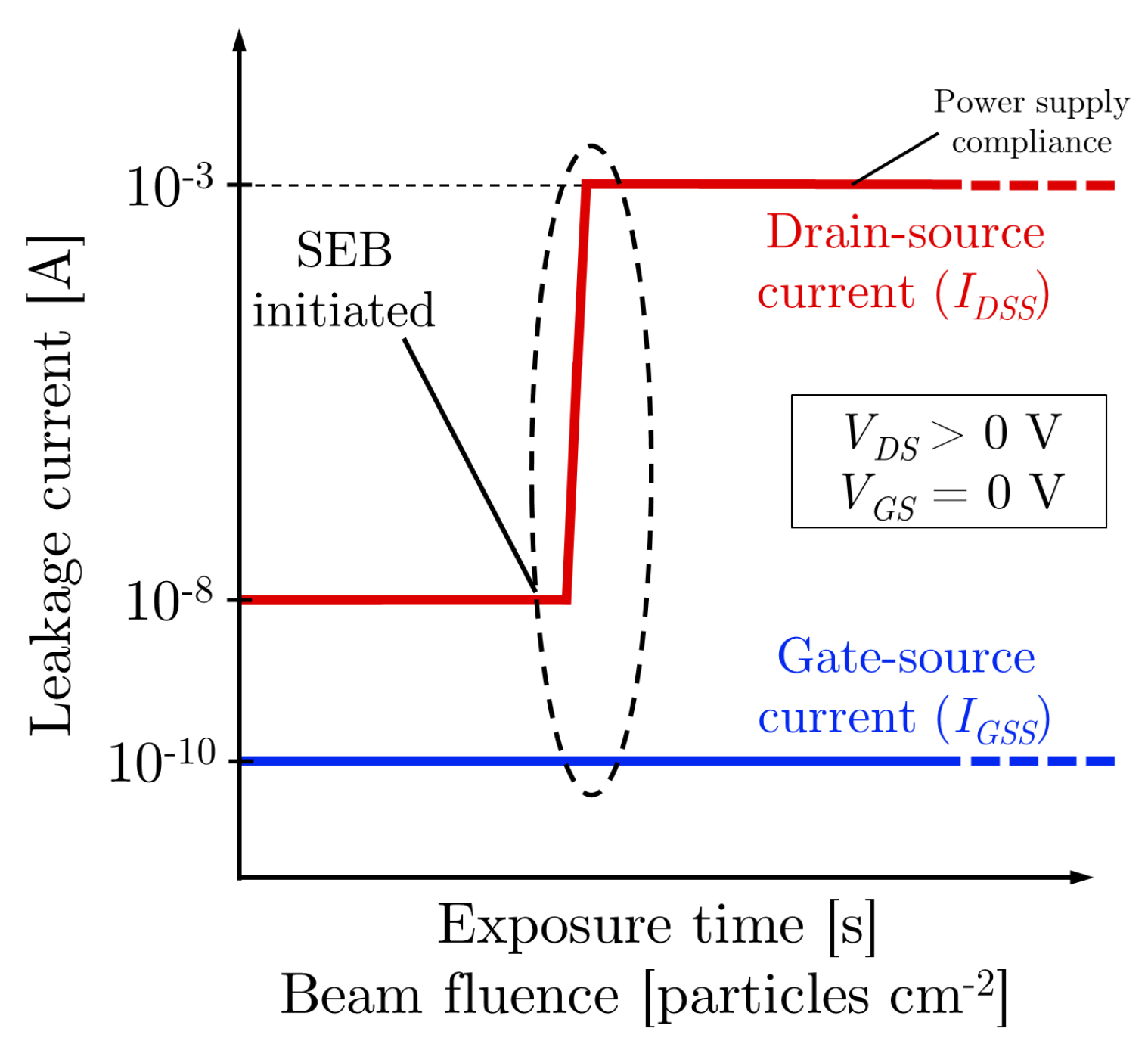
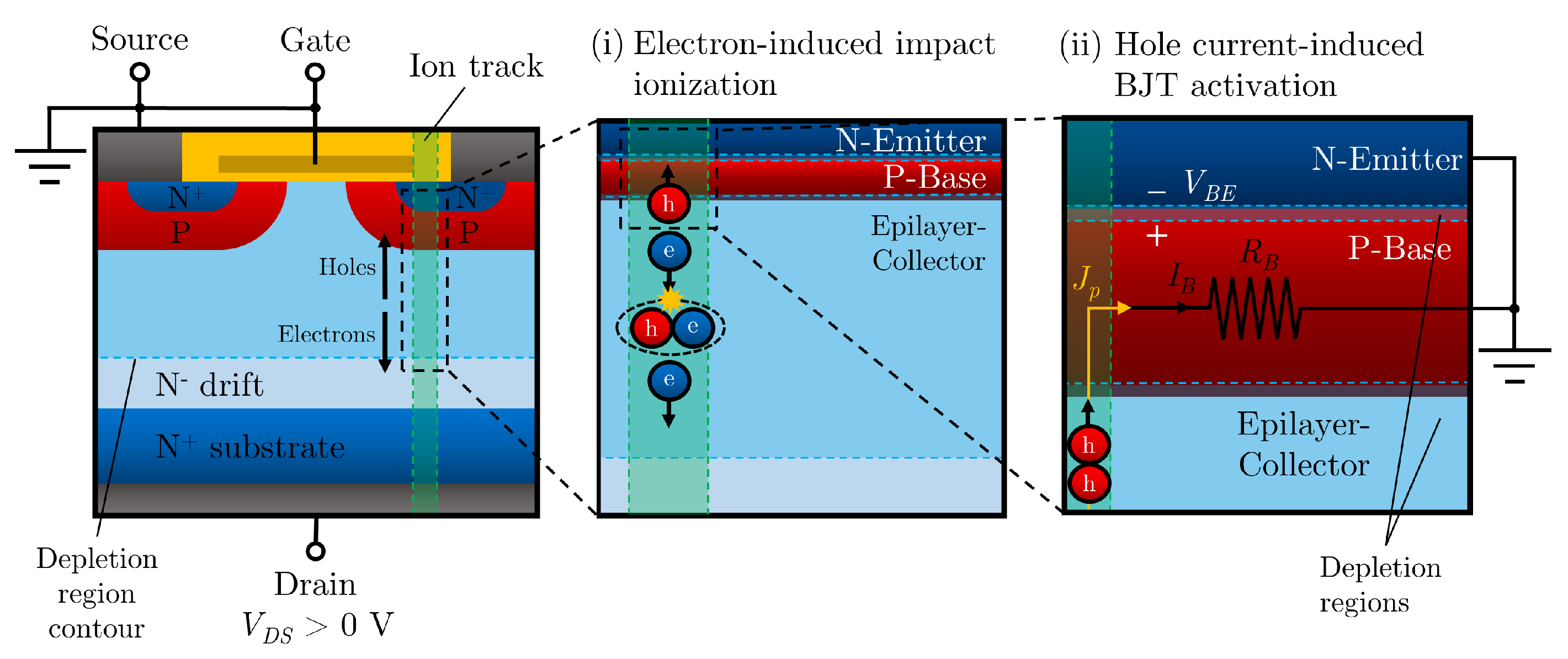
3.6.2. Single-Event Burnout

A single-event burnout occurs when a single energetic particle induces a premature second breakdown, i.e., drain–source breakdown at drain–source voltages below the actual drain–source breakdown voltage ( V DS < B V DS ). It causes a rapid and continuous increase in drain–source current ( I DS ), which leads to localized heating, potentially melting the material and permanently shorting the drain and source electrodes [123]. Unlike SEGR, SEB causes visible physical damage in the DUT [124], as shown in Figure 12. Figure 13 exhibits a typical electrical response following SEB in an N-MOSFET, where a sudden increase in I DSS is observed, limited by test instrumentation and power supply compliance levels.
Single-event breakdown results from the regenerative activation of the parasitic BJT, followed by a second breakdown. This activation can occur via (i) direct triggering due to potential redistribution in the ion track [130] or (ii) an ohmic voltage drop from avalanche processes [131]. The former is more common with high-LET heavy ions, whereas the latter involves progressive activation. Figure 14 illustrates the ion-induced progressive activation of the parasitic BJT. Ion impact generates a plasma filament of electron–hole pairs along the ion track. Subject to the electric field within the N-drift region (epitaxial region), electrons drift toward the N+-substrate and holes move to the P-base region. High electric fields favor avalanche multiplication, increasing hole current in the base, which forward-biases the base–emitter junction, potentially sustaining BJT activation through positive feedback [132,133]. The Current-Induced Avalanche (CIA) model provides an alternative explanation for premature breakdown in epitaxial devices due to ionizing radiation [134]. At high current densities, the peak electric field shifts from the base–collector junction to the epitaxial–substrate interface, a phenomenon known as the Egawa effect [134,135]. If the peak electric field shifts toward the epitaxial–substrate junction and exceeds the critical electric field of the semiconductor material, breakdown occurs.
Unlike SEGR, SEB cross-sections can be measured non-destructively by using the current-limiting technique [136,137], which forms the basis of modern standards for destructive SEE testing [39,41,138]. Although SEB is primarily induced by high-Z energetic ions, it has also been observed to occur in power devices due to protons [139], nuclear reactions [140,141], and neutrons [142,143,144,145]. Several studies have aimed to identify the most relevant physical parameter governing SEB onset [146,147,148,149,150]. Recent findings indicate that SEB onset mainly depends on the charge deposited within the depletion region rather than surface LET [149], supporting the validity of predictive models for ion-induced worst-case response in describing the SEB mechanism [129].

3.7. Neutron Secondary Effects

While charged particles and photons can directly generate charge–carrier pairs, neutrons do not possess electric charge and thus are not capable of ionizing the atoms in a device. However, neutrons do interact with the nuclei of the atoms, and the by-products of these interactions can lead to ionization and thus the effects already discussed. Neutron-induced effects on electronic devices represent the cause of major concerns in several applications, such as commercial avionics and nuclear physics experiments [111,151,152].
The type of interaction that occurs depends on the target material and the neutron energy, but the dominating mechanism is the activation of the material by means of the neutron absorption and subsequent emission of secondary particles. The number and type of particles emitted depend on the stability and internal energy of the compound nucleus. The presence of boron in semiconductor devices is known to be a cause of secondary-particle-induced SEEs due to the reaction 10B(n,4 He)7Li, which releases an alpha particle and lithium-ion recoil inside the device [153].
In silicon materials, several reaction channels can occur depending on the incident neutron energy and isotopic abundance. For instance, when 14 MeV neutrons from deuterium–tritium (D-T) neutron generators interact with 28Si nuclei, the most probable by-products are n + 28 Si (71%), p + 28 Al (24%), and α + 25 Mg (5%). In general, at low energies, elastic and inelastic scattering dominate, whereas at higher energies, more complex reactions involving multiple product emissions (spallation) become prevalent. Besides 252Cf fission sources, deuterium–deuterium, and deuterium–tritium generators, neutron effects can also be studied by using nuclear reactions in low-energy accelerators to produce neutron beams of up to a few MeV [154,155].

4. Impacts on Reliability in Harsh Environments

The qualification of devices under radiation exposure is crucial to proper design, especially when the costs of defective parts can make the project unfeasible. For these assurance tests, guidelines can help engineers to decide on the applicability of a device to a certain environment [156]. In this sense, reliability concepts are fundamental to estimating the mean lifetime of systems subject to failure. The reliability function R ( t ) is simply defined as the probability that a given system remains functional up to time t [157]:
R ( t ) = 1 F ( t ) ,
where F ( t ) represents the Cumulative Density Function (CDF) of failures. A key metric derived from the reliability analysis is the Mean Time to Failure (MTTF), which quantifies the expected operational time before failure occurs [157]:
MTTF = 0 R ( t ) d t .
In the context of SEEs, for the particular case of random failure events with a constant failure rate h ( t ) = SER , the MTTF simplifies to
MTTF = 1 SER ,
where SER is the Single-Event Rate, as given by Equation (5) or (6). For repairable systems, such as those affected by soft errors in digital electronics, it is useful to define the Mean Time Between Failures (MTBF):
MTBF = MTTF + MTTR ,
where MTTR represents the Mean Time to Repair.

4.1. Power Systems

Destructive SEEs are a major concern for power converters operating in harsh radiation environments, such as in space and avionics applications. Unlike SEB and SEL, no protective method has been developed to prevent device destruction once SEGR is initiated [123]. Therefore, SEGR cross-sections in power devices are harder to measure, making the assessment of device reliability in harsh radiation environments difficult compared with other destructive effects.
Some strategies to mitigate destructive SEEs in power converter systems include the following:
  • De-rating: Typically consists in reducing the operating bias by 25% from the destructive SEE onset, preventing or eliminating the occurrence of destructive SEEs.
  • Hardening by design: Structural and process modifications can improve radiation hardness, often at the cost of electrical performance [123]. For instance, SEB robustness in BJTs and MOSFETs can be improved by reducing the parasitic base–emitter resistance and lowering emitter current injection efficiency [158], as well as incorporating optimized buffer layers [159]. SEGR robustness can be improved by reducing neck width and implementing alternative stripe geometries [160].
  • Temperature control: Since the SEB mechanism is strongly dependent on the impact ionization phenomenon, whose rates decrease with the increase in temperature, higher temperatures reduce SEB susceptibility [161]. Conversely, there is generally less susceptibility to SEL at lower temperatures [162].

4.2. Digital Circuits

The occurrence of an SET, depending on its duration and amplitude, can cause a voltage pulse that changes the logic state of a storage element, such as a flip-flop—the so-called bit-flip. This condition depends on the fault latency period, i.e., the time needed for this transient to become an actual error. Modifications in the fabrication process can reduce the amount of charge collected, but these reductions are not sufficient to completely prevent the occurrence of SETs. Therefore, soft error mitigation techniques must still be implemented to ensure reliability, especially considering the growing uses of autonomous systems [163,164,165].
Various fault-tolerant techniques can be applied at different levels to mitigate this risk [163]:
  • Layout- and electrical-level techniques:
    Built-in current sensors (BICSs) are used to detect soft errors by monitoring currents in the bulk region of transistors. These sensors can differentiate ionization events, which cause sharp current spikes, from regular circuit activity. Bulk-BICSs detect SETs with a slight delay, which depends on the number of transistors connected, the intensity of the SET, and the calibration for SET signals. Once an SET is detected, the control logic can perform a fault-tolerant technique. The detection of SETs can be performed even with the use of neural networks [166].
    Transistor resizing is used to increase the capacitance at sensitive nodes, thereby raising the critical charge level required to cause an SET. By increasing the capacitance at these nodes, the circuit becomes less susceptible to radiation-induced errors. However, resizing must be performed carefully to avoid performance and power drawbacks.
  • Logic-level techniques:
    Hardware redundancy, such as duplication with comparison (DWC), where a module is duplicated and the outputs are compared. However, DWC can only indicate that an error has occurred, not which specific part of the logic failed. Parity checking can be used for improved robustness. A more advanced approach is N-modular redundancy (N-MR), where multiple modules (usually three in the case of Triple Modular Redundancy, TMR) are used and a majority voter selects the correct output [167,168,169].
    Time redundancy techniques, such as using two flip-flops with delayed clock signals to capture the output at two distinct times, enabling SET detection. A more advanced approach, full-time redundancy, uses three clocked latches with a majority voter to select the correct output based on multiple observations over time. However, in nanometer technologies, this technique faces challenges when SET pulses last longer than the clock cycle, limiting its effectiveness. The time delay between clocks must be sufficient to capture SETs, but the method becomes impractical when SET durations are comparable to the clock period [170].
    Memory cells can be hardened against SEUs with additional transistors or resistors that allow for the recovery of the stored value when an upset occurs. These techniques typically involve slowing the regenerative feedback of a memory cell or adding feedback mechanisms to restore corrupted data [171]. New materials and technologies for memories also represent a possibility for increasing reliability in harsh environments [172,173]
    Error-correcting codes (ECCs) use information redundancy to mitigate soft errors (SEUs) in integrated circuits. They are primarily used in memory arrays but can also be applied to microprocessor registers and other small memory structures. ECCs can be implemented on hardware or software. Simple ECC methods, like Hamming code, can detect double-bit errors and correct single-bit errors at the cost of including extra check bits, while more complex codes can address multi-bit errors, implemented at hardware and software levels.
  • Architecture-level techniques: The system can be built in order to recompute and restore data with errors, as long as there is redundancy in the data [174,175]
Each fault-tolerant technique introduces trade-offs in terms of design area, performance, and power consumption. The most appropriate techniques and/or combinations must be chosen based on the specific requirements of the application and extensive experiments, using radiation or fault injection techniques [34,176,177,178].

5. Concluding Remarks

The study of radiation effects on semiconductor devices is crucial to applications in harsh environments. While many of the underlying phenomena are well understood, new challenges emerge with each advancing technology, further highlighting the importance of this research area in the context of space exploration and high-reliability devices. New design technologies and novel materials, such as SiC and GaN, offer promising solutions to address reliability challenges in analog and power devices and motivate more research. The miniaturization of digital devices, while benefiting from these developments, also requires an enhanced focus on mitigation techniques. Complex systems, composed of both analog and digital components, such as readout chips for high-energy physics experiments, encompass all of these challenges and may necessitate distinct approaches for their resolution.
To tackle these challenges in a scenario of increasing complexity, it is essential to have access to diverse test facilities capable of simulating various radiation environments and covering a wide energy range. Facilities that can perform combined tests, using multiple radiation sources or different stimuli (thermal, vacuum, and electromagnetic interference), are a trend for the future. Deep analysis of the data and the search for solutions to radiation hardness must also rely on powerful computational resources to improve and successfully apply TCAD models.

Author Contributions

The article was written, reviewed, and approved for publication by V.A.P.A., S.G.A. and M.S.P. All authors have read and agreed to the published version of the manuscript.

Funding

This work was partially funded by Brazilian agencies CNPq (grants Universal 404054/2023-4, INCT-FNA 464898/2014-5, and CPSAE/CNPq 422360/2023) and FAPESP (grant 2023/16053-8).

Conflicts of Interest

The authors declare no conflicts of interest. The funders had no role in the writing of the manuscript or in the decision to publish the results.

References

  1. Ziegler, J.F.; Curtis, H.W.; Muhlfeld, H.P.; Montrose, C.J.; Chin, B.; Nicewicz, M.; Russell, C.A.; Wang, W.Y.; Freeman, L.B.; Hosier, P.; et al. IBM experiments in soft fails in computer electronics (1978–1994). IBM J. Res. Dev. 1996, 40, 3–18. [Google Scholar] [CrossRef]
  2. Heidel, D.; Rodbell, K.; Cannon, E.; Cabral, J.C.; Gordon, M.; Oldiges, P.; Tang, H.H.K. Alpha-particle-induced upsets in advanced CMOS circuits and technology. IBM J. Res. Dev. 2008, 52, 225–232. [Google Scholar] [CrossRef]
  3. Baumann, R.C. Soft Errors in Advanced Semiconductor Devices—Part I: The Three Radiation Sources. IEEE Trans. Device Mater. Reliab. 2001, 1, 17–22. [Google Scholar] [CrossRef]
  4. Schwank, J.R.; Shaneyfelt, M.R.; Dodd, P.E. Radiation Hardness Assurance Testing of Microelectronic Devices and Integrated Circuits: Radiaiton Environments, Physical Mechanisms and Foundations for Hardness Assurance; Document 2008-6851P; Sandia National Laboratories: Albuquerque, NM, USA, 2008. [Google Scholar]
  5. Leroy, C.; Rancoita, P.G. Principles of Radiation Interaction in Matter and Detection, 2nd ed.; World Scientific: Hackensack, NJ, USA, 2009. [Google Scholar]
  6. Ziegler, J.F. Terrestrial cosmic rays. IBM J. Res. Dev. 1996, 40, 19–39. [Google Scholar] [CrossRef]
  7. Di Giovanni, F. Silicon Carbide: Physics, Manufacturing, and Its Role in Large-Scale Vehicle Electrification. Chips 2023, 2, 209–222. [Google Scholar] [CrossRef]
  8. Tian, W.; Ma, T.; Liu, X. TSV Technology and High-Energy Heavy Ions Radiation Impact Review. Electronics 2018, 7, 112. [Google Scholar] [CrossRef]
  9. Gordon, M.; Rodbell, K.; Heidel, D.; Cabral, J.C.; Cannon, E.; Reinhardt, D. Single-Event-Upset and alpha-particle emission rate measurement techniques. IBM J. Res. Dev. 2008, 52, 225–232. [Google Scholar] [CrossRef]
  10. Fleetwood, D.M. Radiation Effects in a Post-Moore World. IEEE Trans. Nucl. Sci. 2021, 68, 509–545. [Google Scholar] [CrossRef]
  11. Benfica, J.; Green, B.; Porcher, B.C.; Poehls, L.B.; Vargas, F.; Medina, N.H.; Added, N.; De Aguiar, V.A.P.; Macchione, E.L.A.; Aguirre, F.; et al. Analysis of SRAM-Based FPGA SEU Sensitivity to Combined EMI and TID-Imprinted Effects. IEEE Trans. Nucl. Sci. 2016, 63, 1294–1300. [Google Scholar] [CrossRef]
  12. Zinkle, S.; Snead, L. Opportunities and limitations for ion beams in radiation effects studies: Bridging critical gaps between charged particle and neutron irradiations. Scr. Mater. 2018, 143, 154–160. [Google Scholar] [CrossRef]
  13. Zhang, Y.; Xue, H.; Zarkadoula, E.; Sachan, R.; Ostrouchov, C.; Liu, P.; Wang, X.l.; Zhang, S.; Wang, T.S.; Weber, W.J. Coupled electronic and atomic effects on defect evolution in silicon carbide under ion irradiation. Curr. Opin. Solid State Mater. Sci. 2017, 21, 285–298. [Google Scholar] [CrossRef]
  14. Zeng, Q.; Yang, Z.; Wang, X.; Li, S.; Gao, F. Research Progress on Radiation Damage Mechanism of SiC MOSFETs Under Various Irradiation Conditions. IEEE Trans. Electron Devices 2024, 71, 1718–1727. [Google Scholar] [CrossRef]
  15. Vogl, T.; Sripathy, K.; Sharma, A.; Reddy, P.; Sullivan, J.; Machacek, J.R.; Zhang, L.; Karouta, F.; Buchler, B.C.; Doherty, M.W.; et al. Radiation tolerance of two-dimensional material-based devices for space applications. Nat. Commun. 2019, 10, 1202. [Google Scholar] [CrossRef]
  16. Lutz, G. Semiconductor Radiation Detectors; Springer: Berlin/Heidelberg, Germany, 1999. [Google Scholar]
  17. Silveira, M.A.G.; Melo, M.A.A.; Aguiar, V.A.P.; Rallo, A.; Santos, R.B.B.; Medina, N.H.; Added, N.; Seixas, L.E.; Leite, F.G.; Cunha, F.G.; et al. A Commercial off-the-shelf pMOS Transistor as X-ray and Heavy Ion Detector. J. Phys. Conf. Ser. 2015, 630, 012012. [Google Scholar] [CrossRef]
  18. Vilas Boas, A.C.; Gabriel Alberton, S.; Medina, N.; Angelo Paulino, V.; Assis Melo, M.A.; Baginski Santos, R.; Giacomini, R.; Cavalcante, T.; Galhardo Vaz, R.; Junior, E.; et al. Reliability analysis of gamma- and X-ray TID effects, on a commercial AlGaN/GaN based FET. JICS 2021, 16, 1–7. [Google Scholar] [CrossRef]
  19. Fleetwood, D.M. Total-Ionizing-Dose Effects, Border Traps, and 1/F Noise Emerging MOS Technologies. IEEE Trans. Nucl. Sci. 2020, 67, 1216–1240. [Google Scholar] [CrossRef]
  20. Stoller, R.; Toloczko, M.; Was, G.; Certain, A.; Dwaraknath, S.; Garner, F. On the use of SRIM for computing radiation damage exposure. Nucl. Instrum. Methods Phys. Res. Sect. B Beam Interact. Mater. Atoms 2013, 310, 75–80. [Google Scholar] [CrossRef]
  21. Duzellier, S. Radiation effects on electronic devices in space. Aerosp. Sci. Technol. 2005, 9, 93–99. [Google Scholar] [CrossRef]
  22. Pan, S.; Feng, S.; Li, X.; Zheng, X.; Lu, X.; Hu, C.; Shao, G.; Lin, G. Analysis of the Effects of High-Energy Electron Irradiation of GaN High-Electron-Mobility Transistors Using the Voltage-Transient Method. IEEE Trans. Electron Devices 2021, 68, 3968–3973. [Google Scholar] [CrossRef]
  23. Soibel, A.; Rafol, S.B.; Khoshakhlagh, A.; Nguyen, J.; Hoglund, L.; Fisher, A.M.; Keo, S.A.; Ting, D.Z.Y.; Gunapala, S.D. Proton radiation effect on performance of InAs/GaSb complementary barrier infrared detector. Appl. Phys. Lett. 2015, 107, 261102. [Google Scholar] [CrossRef]
  24. Yuan, Y.; Zhou, S.; Wang, X. Modulating properties by light ion irradiation: From novel functional materials to semiconductor power devices. J. Semicond. 2022, 43, 063101. [Google Scholar] [CrossRef]
  25. Arnold, K.P.; Musibau, S.; Dattilo, H.M.; Sutton, H.J.; Frankowski, S.L.; Berciano, M.; Zhang, E.X.; McCurdy, M.W.; Crespillo, M.L.; Hattar, K.; et al. Displacement Damage and Ionization Effects on Waveguide-Integrated Germanium-Silicon PIN Photodiodes. IEEE Trans. Nucl. Sci. 2025, 1. [Google Scholar] [CrossRef]
  26. Xi, J.; Zhang, H.; Su, R.; Wei, S.; Hu, X.; Queylat, B.; Kim, T.; Couet, A.; Szlufarska, I. Coupling of radiation and grain boundary corrosion in SiC. NPJ Mater. Degrad. 2024, 8, 16. [Google Scholar] [CrossRef]
  27. Guazzelli, M.; Avanzi, L.; Aguiar, V.; Vilas-Boas, A.; Alberton, S.; Masunaga, S.; Chinaglia, E.; Araki, K.; Nakamura, M.; Toyama, M.; et al. Effects of neutron radiation on the thermal conductivity of highly oriented pyrolytic graphite. Diam. Relat. Mater. 2025, 151, 111803. [Google Scholar] [CrossRef]
  28. Ullah, M.W.; Zhang, Y.; Sellami, N.; Debelle, A.; Bei, H.; Weber, W.J. Evolution of irradiation-induced strain in an equiatomic NiFe alloy. Scr. Mater. 2017, 140, 35–39. [Google Scholar] [CrossRef]
  29. Baubekova, G.; Akilbekov, A.; Feldbach, E.; Grants, R.; Manika, I.; Popov, A.; Schwartz, K.; Vasil’chenko, E.; Zdorovets, M.; Lushchik, A. Accumulation of radiation defects and modification of micromechanical properties under MgO crystal irradiation with swift 132Xe ions. Nucl. Instrum. Methods Phys. Res. Sect. B Beam Interact. Mater. Atoms 2020, 463, 50–54. [Google Scholar] [CrossRef]
  30. Tang, H.H.K. Nuclear physics of cosmic ray interaction with semiconductor materials: Particle-induced soft errors from a physicist’s perspective. IBM J. Res. Dev. 1996, 40, 91–108. [Google Scholar] [CrossRef]
  31. Sierawski, B.D.; Warren, K.M.; Reed, R.A.; Weller, R.A.; Mendenhall, M.M.; Schrimpf, R.D.; Baumann, R.C.; Zhu, V. Contribution of Low Energy (<10 MeV) Neutrons to Upset Rate in a 65 nm SRAM. In Proceedings of the 2010 IEEE International Reliability Physics Symposium, Anaheim, CA, USA, 2–6 May 2010; pp. 4B.2.1–4B.2.5. [Google Scholar]
  32. Rodbell, K.; Heidel, D.; Tang, H.; Gordon, M.; Oldiges, P.; Murray, C. Low-energy proton-induced single-event-upsets in 65 nm node, silicon-on-insulator, latches and memory cells. IEEE Trans. Nucl. Sci. 2007, 54, 2474–2479. [Google Scholar] [CrossRef]
  33. Barak, J.; Murat, M.; Akkerman, A. SEU due to electrons in silicon devices with nanometric sensitive volumes and small critical charge. Nucl. Instrum. Methods Phys. Res. 2012, 287, 113–119. [Google Scholar] [CrossRef]
  34. Velazco, R.; Fouillat, P.; Reis, R.A.d.L. Radiation Effects on Embedded Systems; Springer: Dordrecht, The Netherlands, 2007. [Google Scholar]
  35. Petersen, E.L. Dosimetry Comparisons Between Various Single Event Test Facilities. IEEE Trans. Nucl. Sci. 2010, 57, 3477–3482. [Google Scholar] [CrossRef]
  36. Medina, N.H.; de Aguiar, V.Â.; Added, N.; Aguirre, F.; Macchione, E.L.; Alberton, S.G.; da Silva, M.A.; Benfica, J.; Vargas, F.L.; Porcher, B. Experimental Setups for Single Event Effect Studies. JNP 2016, 4, 13–23. [Google Scholar] [CrossRef]
  37. Aguiar, V.; Added, N.; Medina, N.; Macchione, E.; Tabacniks, M.; Aguirre, F.; Silveira, M.; Santos, R.; Seixas, L. Experimental setup for Single Event Effects at the São Paulo 8UD Pelletron Accelerator. Nucl. Instrum. Methods Phys. Res. Sect. B Beam Interact. Mater. Atoms 2014, 332, 397–400. [Google Scholar] [CrossRef]
  38. F1192-00; Standard Guide for the Measurement of Single Event Phenomena (SEP) Induced by Heavy Ion Irradiation of Semiconductor Devices. ASTM Standard. American Society for Testing and Materials: West Conshohocken, PA, USA, 2006.
  39. European Space Agency. Single Event Effects Test Method and Guidelines, ESCC Basic Specification No. 25100; Technical Report; European Space Agency: Paris, France, 2014. [Google Scholar]
  40. ESA/SCC Basic Specification 22900; Total Dose Steady-State Irradiation Test Method. ESA/SCC Basic Specification 1. European Space Agency: Paris, France, 1995.
  41. JEDEC-JESD57A; Test Procedures for the Measurement of Single-Event Effects in Semiconductor Devices from Heavy-Ion Irradiation. Technical Report. JEDEC Solid State Technology Association: Arlington County, VA, USA, 2017.
  42. Ziegler, J.F.; Biersack, J.; Ziegler, M. SRIM: The Stopping and Range of Ions in Matter; SRIM Co.: Hyderabad, India, 2008. [Google Scholar]
  43. Wyss, J.; Bisello, D.; Pantano, D. SIRAD: An irradiation facility at the LNL Tandem accelerator for radiation damage studies on semiconductor detectors and electronic devices and systems. Nucl. Instrum. Methods Phys. Res. A 2001, 462, 426–434. [Google Scholar] [CrossRef]
  44. Mattiazzo, S.; Bisello, D.; Giubilato, P.; Kaminsky, A.; Pantano, D.; Silvestrin, L.; Tessaro, M.; Wyss, J. First results in micromapping the sensivity to SEE of an electronic device in a SOI technology at the LNL IEEM. Nucl. Instrum. Methods Phys. Res. A 2011, 658, 125–128. [Google Scholar] [CrossRef]
  45. Silvestrin, L.; Bisello, D.; Busatto, G.; Giubilato, P.; Iannuzzo, F.; Mattiazzo, S.; Pantano, D.; Sanseverino, A.; Tessaro, M.; Velardi, F.; et al. A time-resolved IBICC experiment using the IEEMof the SIRAD facility. Nucl. Instrum. Methods Phys. Res. B 2012, 273, 234–236. [Google Scholar] [CrossRef]
  46. Palomo, F.R.; Morilla, Y.; Mogollón, J.M.; García-López, J.; Labrador, J.A.; Aguirre, M.A. Early works on the nuclear microprobe for microelectronics irradiation tests at the CEICI (Sevilla, Spain). Nucl. Instrum. Methods Phys. Res. B 2011, 269, 2210–2216. [Google Scholar] [CrossRef]
  47. Aguiar, V.A.P.; Medina, N.H.; Added, N.; Macchione, E.L.A.; Alberton, S.G.; Leite, A.R.; Aguirre, F.R.; Ribas, R.V.; Perego, C.C.; Fagundes, L.M.; et al. SAFIIRA: A heavy-ion multi-purpose irradiation facility in Brazil. Rev. Sci. Instrum. 2020, 91, 053301. [Google Scholar] [CrossRef]
  48. Tonfat, J.; Lima Kastensmidt, F.; Artola, L.; Hubert, G.; Medina, N.H.; Added, N.; Aguiar, V.A.P.; Aguirre, F.; Macchione, E.L.A.; Silveira, M.A.G. Analyzing the Influence of the Angles of Incidence and Rotation on MBU Events Induced by Low LET Heavy Ions in a 28-nm SRAM-Based FPGA. IEEE Trans. Nucl. Sci. 2017, 64, 2161–2168. [Google Scholar] [CrossRef]
  49. Petersen, E. Single Event Effects in Aerospace; John Wiley & Sons: Hoboken, NJ, USA, 2011. [Google Scholar]
  50. Gu, S.; Liu, J.; Bi, J.; Zhao, F.; Zhang, Z.; Xi, K.; Peng, K.; Zhang, Y. The Impacts of Heavy Ion Energy on Single Event Upsets in SOI SRAMs. IEEE Trans. Nucl. Sci. 2018, 65, 1091–1100. [Google Scholar] [CrossRef]
  51. Alia, R.G.; Bahamonde, C.; Brandenburg, S.; Brugger, M.; Daly, E.; Ferlet-Cavrois, V.; Gaillard, R.; Hoeffgen, S.; Menicucci, A.; Metzger, S.; et al. Sub-LET Threshold SEE Cross Section Dependency with Ion Energy. IEEE Trans. Nucl. Sci. 2015, 62, 2797–2806. [Google Scholar] [CrossRef]
  52. Petersen, E.L. Single-Event Data Analysis. IEEE Trans. Nucl. Sci. 2008, 55, 2819–2841. [Google Scholar] [CrossRef]
  53. Inguimbert, C.; Duzellier, S.; Nuns, T.; Bezerra, F. Using Subthreshold Heavy Ion Upset Cross Section to Calculate Proton Sensitivity. IEEE Trans. Nucl. Sci. 2007, 54, 2394–2399. [Google Scholar] [CrossRef]
  54. Connell, L.; McDaniel, P.; Prinja, A.; Sexton, F. Modeling the Heavy Ion Upset Cross Section. IEEE Trans. Nucl. Sci. 1995, 42. [Google Scholar] [CrossRef]
  55. Dodd, P.E. Physics-based simulation of single-event effects. IEEE Trans. Device Mater. Reliab. 2005, 5, 343–357. [Google Scholar] [CrossRef]
  56. Srinivasan, G.; Tang, H.; Murley, P. Parameter-free, predictive modeling of single event upsets due to protons, neutrons and pions in terrestrial cosmic rays. IEEE Trans. Nucl. Sci. 1994, 41, 2063–2070. [Google Scholar] [CrossRef]
  57. Tang, H.; Cannon, E.H. SEMM-2: A Modeling System for Single Event Upset Analysis. IEEE Trans. Nucl. Sci. 2004, 51, 3342–3348. [Google Scholar] [CrossRef]
  58. Li, Y.; Yu, D.; Zhang, Q.; Cai, Z.; Jia, X.; Wang, Y. Qcrit-independent model method for proton SEU analysis. Microelectron. Reliab. 2019, 93, 72–80. [Google Scholar] [CrossRef]
  59. Murat, M.; Akkerman, A.; Barak, J. Electron and ion tracks in silicon: Spatial and temporal evolution. IEEE Trans. Nucl. Sci. 2008, 55, 3046–3054. [Google Scholar] [CrossRef]
  60. Wrobel, F.; Hubert, G.; Iacconi, P. A semi-empirical approach for heavy ion SEU cross section calculations. IEEE Trans. Nucl. Sci. 2006, 53, 3271–3276. [Google Scholar] [CrossRef]
  61. Sogoyan, A.; Chumakov, A.; Smolin, A.; Ulanova, A.; Boruzdina, A. A simple analytical model of single-event upsets in bulk CMOS. Nucl. Instrum. Methods Phys. Res. B 2017, 400, 31–36. [Google Scholar] [CrossRef]
  62. Normand, E. Single-event effects in avionics. IEEE Trans. Nucl. Sci. 1996, 43, 461–474. [Google Scholar] [CrossRef]
  63. Normand, E. Single event upset at ground level. IEEE Trans. Nucl. Sci. 1996, 43, 2742–2750. [Google Scholar] [CrossRef]
  64. JESD89-3B; Test Method For Beam Accelerated Soft Error Rate. EIA/JEDEC Standard. Electronic Industries Association: Arlington County, VA, USA, 2021.
  65. McLean, F.; Oldham, T. Charge funneling in n- and p-type Si substrates. IEEE Trans. Nucl. Sci. 1982, 29, 2017–2023. [Google Scholar] [CrossRef]
  66. Oldham, T.R.; McLean, F.B.; Hartman, J.M. Revised funnel calculations for heavy particles with high dE/dx. IEEE Trans. Nucl. Sci. 1986, 33, 1646–1650. [Google Scholar] [CrossRef]
  67. Liu, J.; Yan, S.; Xue, J.; Wang, Y. Comparison of ionization track structure models for electronic devices of different sizes. Nucl. Instrum. Methods Phys. Res. B 2019, 444, 43–49. [Google Scholar] [CrossRef]
  68. Edmonds, L. Electric currents through ion tracks in silicon devices. IEEE Trans. Nucl. Sci. 1998, 45, 3153–3164. [Google Scholar] [CrossRef]
  69. Ahlbin, J.; Gadlage, M.; Atkinson, N.; Narasimham, B.; Bhuva, B.; Witulski, A.; Holman, W.; Eaton, P.; Massengill, L. Effect of Multiple-Transistor Charge Collection on Single-Event Transient Pulse Widths. IEEE Trans. Device Mater. Reliab. 2011, 11, 401–406. [Google Scholar] [CrossRef]
  70. Musseau, O. Charge collection and SEU mechanisms. Radiat. Phys. Chem. 1994, 43, 151–163. [Google Scholar] [CrossRef]
  71. Hu, C. Alpha-particle-induced field and enhanced collection of carriers. IEEE Electron Device Lett. 1982, 3, 31–34. [Google Scholar] [CrossRef]
  72. Takada, M.; Nunomiya, T.; Ishikura, T.; Nakamura, T. Charge-Collection Length Induced by Proton and Alpha Particle Injected Into Silicon Detectors Due to Funneling Effect. IEEE Trans. Nucl. Sci. 2009, 56, 337–345. [Google Scholar] [CrossRef]
  73. Aguiar, V.A.P.; Medina, N.H.; Added, N.; Alberton, S.G.; Macchione, E.L.A.; Guazzelli, M.A.; Melo, M.A.A.; Oliveira, J.A.; Giacomini, R.C.; Aguirre, F.R.; et al. Evaluation of Funnel Models on Calculation of Ion-Induced Collected Charge. IEEE Trans. Electron Devices 2025, 72, 31–36. [Google Scholar] [CrossRef]
  74. Edmonds, L.D. A theoretical analysis of steady-state charge collection in simple diodes under high-injection conditions. IEEE Trans. Nucl. Sci. 2010, 57, 818–830. [Google Scholar] [CrossRef]
  75. Edmonds, L.D. A theoretical analysis of the role of ambipolar diffusion in charge-carrier transport in a quasi-neutral region under high injection. IEEE Trans. Nucl. Sci. 2011, 58, 2459–2469. [Google Scholar] [CrossRef]
  76. Edmonds, L.D. A proposed transient version of the ADC charge-collection model tested against TCAD. IEEE Trans. Nucl. Sci. 2011, 58, 296–304. [Google Scholar] [CrossRef]
  77. Hooten, N.; Edmonds, L.; Bennett, W.; Ahlbin, J.; Dodds, N.; Reed, R.; Schrimpf, R.; Weller, R. The significance of high-level carrier generation conditions for charge collection in irradiated devices. IEEE Trans. Nucl. Sci. 2012, 59, 2710–2721. [Google Scholar] [CrossRef]
  78. Assis, T.; Ni, K.; Kauppila, J.; Bhuva, B.; Schrimpf, R.; Massengill, L.; Wen, S.; Wong, R.; Slayman, C. Estimation of single-event-induced collected charge for multiple transistors using analytical expressions. IEEE Trans. Nucl. Sci. 2015, 62, 2853–2859. [Google Scholar] [CrossRef]
  79. Choo, K.; Muniandy, S.; Woon, K.; Gan, M.; Ong, D. Modeling anomalous charge carrier transport in disordered organic semiconductors using the fractional drift-diffusion equation. Org. Electron. 2017, 41, 157–165. [Google Scholar] [CrossRef]
  80. Ma, H.; Wang, W.; Cai, Y.; Wang, Z.; Zhang, T.; Feng, Q.; Chen, Y.; Zhang, C.; Zhang, J.; Hao, Y. Analysis of single event effects by heavy ion irradiation of Ga2O3 metal–oxide–semiconductor field-effect transistors. J. Appl. Phys. 2023, 133, 085701. [Google Scholar] [CrossRef]
  81. Ni, K.; Zhang, E.X.; Samsel, I.K.; Schrimpf, R.D.; Reed, R.A.; Fleetwood, D.M.; Sternberg, A.L.; McCurdy, M.W.; Ren, S.; Ma, T.P.; et al. Charge Collection Mechanisms in GaAs MOSFETs. IEEE Trans. Nucl. Sci. 2015, 62, 2752–2759. [Google Scholar] [CrossRef]
  82. Boorboor, S.; Feghhi, S.; Jafari, H. Funneling effect of alpha particles on the charge collection efficiency in N type silicon surface barrier detector. Nucl. Instrum. Methods Phys. Res. B 2014, 325, 1–4. [Google Scholar] [CrossRef]
  83. Lopez, J.G.; Jimenez-Ramos, M.; Rodrigues-Ramos, M.; Forneris, J.; Ceballos, J. An upgraded drift-diffusion model for evaluating the carrier lifetimes in radiation-damaged semiconductor detectors. Nucl. Instrum. Methods Phys. Res. B 2016, 371, 294–297. [Google Scholar] [CrossRef]
  84. Kunc, J.; Praus, P.; Belas, E.; Dědič, V.; Pekárek, J.; Grill, R. Efficient Charge Collection in Coplanar-Grid Radiation Detectors. Phys. Rev. Appl. 2018, 9, 054020. [Google Scholar] [CrossRef]
  85. Ziegler, J.F.; Ziegler, M.D.; Biersack, J.P. SRIM—The Stopping and Range of Ions in Matter (2010). Nucl. Instrum. Methods Phys. Res. Sect. B Beam Interact. Mater. Atoms 2010, 268, 1818–1823. [Google Scholar] [CrossRef]
  86. Agostinelli, S.; Allison, J.; Amako, K.; Apostolakis, J.; Araujo, H.; Arce, P.; Asai, M.; Axen, D.; Banerjee, S.; Barrand, G.; et al. Geant4—A simulation toolkit. Nucl. Instrum. Methods Phys. Res. Sect. A Accel. Spectrometers Detect. Assoc. Equip. 2003, 506, 250–303. [Google Scholar] [CrossRef]
  87. Lucsányi, D.; Alía, R.G.; Biłko, K.; Cecchetto, M.; Fiore, S.; Pirovano, E. G4SEE: A Geant4-based Single Event Effect Simulation Toolkit and its Validation Through Monoenergetic Neutron Measurements. IEEE Trans. Nucl. Sci. 2022, 69, 273–281. [Google Scholar] [CrossRef]
  88. Wu, Y.C.; Jhan, Y.R. Introduction of Synopsys Sentaurus TCAD Simulation. In 3D TCAD Simulation for CMOS Nanoeletronic Devices; Springer: Singapore, 2018; pp. 1–17. [Google Scholar] [CrossRef]
  89. ATLAS User’s Manual. Available online: https://www.eng.buffalo.edu/~wie/silvaco/atlas_user_manual.pdf (accessed on 3 March 2025).
  90. Michez, A.; Dhombres, S.; Boch, J. ECORCE: A TCAD Tool for Total Ionizing Dose and Single Event Effect Modeling. IEEE Trans. Nucl. Sci. 2015, 62, 1516–1527. [Google Scholar] [CrossRef]
  91. Rossi, C.; Chatel, A.; Sallese, J. Modeling Funneling Effect with Generalized Devices for SPICE Simulation of Soft Errors. IEEE Trans. Electron Devices 2021, 68, 2633–2640. [Google Scholar] [CrossRef]
  92. Aneesh, Y.M.; Sriram, S.R.; Pasupathy, K.R.; Bindu, B. An Analytical Model of Single-Event Transients in Double-Gate MOSFET for Circuit Simulation. IEEE Trans. Electron Devices 2019, 66, 3710–3717. [Google Scholar] [CrossRef]
  93. TCAD Central. Available online: https://tcadcentral.com/index.html (accessed on 3 March 2025).
  94. King, M.P.; Reed, R.A.; Weller, R.A.; Mendenhall, M.H.; Schrimpf, R.D.; Sierawski, B.D.; Sternberg, A.L.; Narasimham, B.; Wang, J.K.; Pitta, E.; et al. Electron-Induced Single-Event Upsets in Static Random Access Memory. IEEE Trans. Nucl. Sci. 2013, 60, 4122–4129. [Google Scholar] [CrossRef]
  95. Spieler, H. Semiconductor Detector Systems; Series on semiconductor science and technology; Oxford University Press: Oxford, UK, 2005. [Google Scholar] [CrossRef]
  96. Knoll, G.F. Radiation Detection and Measurement; Wiley: New York, NY, USA, 2000. [Google Scholar]
  97. Sze, S.M. Physics of Semiconductor Devices, 2nd ed.; John Wiley & Sons: Hoboken, NJ, USA, 1981. [Google Scholar]
  98. Deen, M.J.; Pascal, F. Electrical Characterization of Semiconductor Materials and Devices. In Springer Handbook of Electronic and Photonic Materials; Kasap, S., Capper, P., Eds.; Springer International Publishing: Cham, Switzerland, 2017; p. 1. [Google Scholar] [CrossRef]
  99. Dalla Betta, G.F.; Ye, J. Silicon Radiation Detector Technologies: From Planar to 3D. Chips 2023, 2, 83–101. [Google Scholar] [CrossRef]
  100. Turchetta, R.; Fant, A.; Gasiorek, P.; Esbrand, C.; Griffiths, J.; Metaxas, M.; Royle, G.; Speller, R.; Venanzi, C.; van der Stelt, P.; et al. CMOS Monolithic Active Pixel Sensors (MAPS): Developments and future outlook. Nucl. Instrum. Methods Phys. Res. Sect. A Accel. Spectrometers Detect. Assoc. Equip. 2007, 582, 866–870. [Google Scholar] [CrossRef]
  101. Korol, I. Beam test characterization of CMS silicon pixel detectors for the phase-1 upgrade. Nucl. Instrum. Methods Phys. Res. Sect. A Accel. Spectrometers Detect. Assoc. Equip. 2015, 796, 64–67. [Google Scholar] [CrossRef]
  102. Zaťko, B.; Zápražný, Z.; Jakůbek, J.; Šagátová, A.; Boháček, P.; Sekáčová, M.; Korytár, D.; Nečas, V.; Žemlička, J.; Mora, Y.; et al. Imaging performance of a Timepix detector based on semi-insulating GaAs. J. Instrum. 2018, 13, C01034. [Google Scholar] [CrossRef]
  103. Amendolia, S.; Bertolucci, E.; Bisogni, M.; Bottigli, U.; Ciocci, M.; Conti, M.; Delogu, P.; Fantacci, M.; Maestro, P.; Marzulli, V.; et al. GaAs detector optimization for different medical imaging applications. Nucl. Instrum. Methods Phys. Res. Sect. A Accel. Spectrometers Detect. Assoc. Equip. 1999, 434, 14–17. [Google Scholar] [CrossRef]
  104. Šagátová, A.; Kubanda, D.; Zat’Ko, B.; Sedlačková, K.; Nečas, V.; Solar, M.; Granja, C. Semi-insulating GaAs based detector of fast neutrons produced by D-T nuclear reaction. J. Instrum. 2016, 11, C12002. [Google Scholar] [CrossRef]
  105. Wu, X.; Peltola, T.; Arsenovich, T.; Gädda, A.; Härkönen, J.; Junkes, A.; Karadzhinova, A.; Kostamo, P.; Lipsanen, H.; Luukka, P.; et al. Processing and characterization of epitaxial GaAs radiation detectors. Nucl. Instrum. Methods Phys. Res. Sect. A Accel. Spectrometers Detect. Assoc. Equip. 2015, 796, 51–55. [Google Scholar] [CrossRef]
  106. Chernykh, S.; Chernykh, A.; Didenko, S.; Baryshnikov, F.; Burtebayev, N.; Britvich, G.; Chubenko, A.; Guly, V.; Glybin, Y.; Zholdybayev, T.; et al. GaAs detectors with an ultra-thin Schottky contact for spectrometry of charged particles. Nucl. Instrum. Methods Phys. Res. Sect. A Accel. Spectrometers Detect. Assoc. Equip. 2017, 845, 52–55. [Google Scholar] [CrossRef]
  107. Pereira, M.S.; Aguiar, V.A.P.; Alberton, S.G.; Quivy, A.A. Response testing of Schottky-barrier GaAs detectors with alpha particles. J. Phys. Conf. Ser. 2022, 2340, 012050. [Google Scholar] [CrossRef]
  108. Tudisco, S.; Altana, C.; Boscardin, M.; Calcagno, L.; Ciampi, C.; Cirrone, G.A.; Fazzi, A.; Giove, D.; Gorini, G.; Labate, L.; et al. Silicon carbide for future intense luminosity nuclear physics investigations. Il Nuovo Cimento C 2019, 42, 1–4. [Google Scholar] [CrossRef]
  109. Puglisi, D.; Bertuccio, G. Silicon Carbide Microstrip Radiation Detectors. Micromachines 2019, 10, 835. [Google Scholar] [CrossRef]
  110. Lopez Paz, I.; Godignon, P.; Moffat, N.; Pellegrini, G.; Rafí, J.M.; Rius, G. Position-resolved charge collection of silicon carbide detectors with an epitaxially-grown graphene layer. Sci. Rep. 2024, 14, 10376. [Google Scholar] [CrossRef] [PubMed]
  111. Cappuzzello, F.; Agodi, C.; Calabretta, L.; Calvo, D.; Carbone, D.; Cavallaro, M.; Colonna, M.; Finocchiaro, P.; Iazzi, F.; Linares, R.; et al. The NUMEN Technical Design Report. Int. J. Mod. Phys. A 2021, 36, 2130018. [Google Scholar] [CrossRef]
  112. Azarov, A.; Fernandez, J.G.; Zhao, J.; Djurabekova, F.; He, H.; He, R.; Prytz, O.; Vines, L.; Bektas, U.; Chekhonin, P.; et al. Universal radiation tolerant semiconductor. Nat. Commun. 2023, 14, 4855. [Google Scholar] [CrossRef] [PubMed]
  113. Konovalov, V.; Roeder, B. Diamond ΔE-E telescope with an ultra-thin ΔE-diamond detector. Diam. Relat. Mater. 2024, 145, 111120. [Google Scholar] [CrossRef]
  114. He, Y.; Hadar, I.; Kanatzidis, M.G. Detecting ionizing radiation using halide perovskite semiconductors processed through solution and alternative methods. Nat. Photon. 2022, 16, 14–26. [Google Scholar] [CrossRef]
  115. Lang, F.; Jošt, M.; Frohna, K.; Köhnen, E.; Al-Ashouri, A.; Bowman, A.R.; Bertram, T.; Morales-Vilches, A.B.; Koushik, D.; Tennyson, E.M.; et al. Proton Radiation Hardness of Perovskite Tandem Photovoltaics. Joule 2020, 4, 1054–1069. [Google Scholar] [CrossRef]
  116. Tan, R.; Dryzhakov, B.; Charest, J.; Hu, B.; Ahmadi, M.; Lukosi, E. Improved Radiation Sensing with Methylammonium Lead Tribromide Perovskite Semiconductors. Nucl. Instrum. Methods Phys. Res. Sect. A Accel. Spectrometers Detect. Assoc. Equip. 2021, 986, 164710. [Google Scholar] [CrossRef]
  117. Pickel, J.C.; Blandford, J.T. Cosmic-ray-induced errors in MOS devices. IEEE Trans. Nucl. Sci. 1980, 27, 1006–1015. [Google Scholar] [CrossRef]
  118. Stephen, J.H.; Sanderson, T.K.; Mapper, D.; Farren, J.; Harboe-Sorensen, R.; Adams, L. Cosmic ray simulation experiments for the study of single event upsets and latch-up in CMOS memories. IEEE Trans. Nucl. Sci. 1983, 30, 4464–4469. [Google Scholar] [CrossRef]
  119. Waskiewicz, A.E.; Groninger, J.W.; Strahan, V.H.; Long, D.M. Burnout of power MOS transistors with heavy ions of Californium-252. IEEE Trans. Nucl. Sci. 1986, 33, 1710–1713. [Google Scholar] [CrossRef]
  120. Brucker, G.J.; Measel, P.; Oberg, D.; Wert, J.; Criswell, T. SEU sensitivity of power converters with MOSFETS in space. IEEE Trans. Nucl. Sci. 1987, 34, 1792–1795. [Google Scholar] [CrossRef]
  121. Pickel, J.C.; Blandford, J.T.; Waskiewicz, A.E.; Strahan, V.H. Heavy ion induced permanent damage in MNOS gate insulators. IEEE Trans. Nucl. Sci. 1985, 32, 4176–4179. [Google Scholar] [CrossRef]
  122. Ochoa, A.; Sexton, F.W.; Wrobel, T.F.; Hash, G.L.; Sokel, R.J. Snap-back: A stable regenerative breakdown mode of MOS devices. IEEE Trans. Nucl. Sci. 1983, 30, 4127–4130. [Google Scholar] [CrossRef]
  123. Sexton, F.W. Destructive single-event effects in semiconductor devices and ICs. IEEE Trans. Nucl. Sci. 2003, 50, 603–621. [Google Scholar] [CrossRef]
  124. Titus, J.L. An updated perspective of single event gate rupture and single event burnout in power MOSFETs. IEEE Trans. Nucl. Sci. 2013, 60, 1912–1928. [Google Scholar] [CrossRef]
  125. Wheatley, C.F.; Titus, J.L.; Burton, D.I. Single-event gate rupture in vertical power MOSFETs; an original empirical expression. IEEE Trans. Nucl. Sci. 1994, 41, 2152–2159. [Google Scholar] [CrossRef]
  126. Titus, J.; Wheatley, C.; Burton, D.; Mouret, I.; Allenspach, M.; Brews, J.; Schrimpf, R.; Galloway, K.; Pease, R. Impact of oxide thickness on SEGR failure in vertical power MOSFETs; development of a semi-empirical expression. IEEE Trans. Nucl. Sci. 1995, 42, 1928–1934. [Google Scholar] [CrossRef]
  127. Titus, J.L.; Wheatley, C.F. Experimental studies of single-event gate rupture and burnout in vertical power MOSFETs. IEEE Trans. Nucl. Sci. 1996, 43, 533–545. [Google Scholar] [CrossRef]
  128. Titus, J.; Wheatley, C.; Van Tyne, K.; Krieg, J.; Burton, D.; Campbell, A. Effect of ion energy upon dielectric breakdown of the capacitor response in vertical power MOSFETs. IEEE Trans. Nucl. Sci. 1998, 45, 2492–2499. [Google Scholar] [CrossRef]
  129. Titus, J.L.; Wheatley, C.F. SEE characterization of vertical DMOSFETs: An updated test protocol. IEEE Trans. Nucl. Sci. 2003, 50, 2341–2351. [Google Scholar] [CrossRef]
  130. Kuboyama, S.; Matsuda, S.; Kanno, T.; Ishii, T. Mechanism for single-event burnout of power MOSFETs and its characterization technique. IEEE Trans. Nucl. Sci. 1992, 39, 1698–1703. [Google Scholar] [CrossRef]
  131. Johnson, G.; Palau, J.; Dachs, C.; Galloway, K.; Schrimpf, R. A review of the techniques used for modeling single-event effects in power MOSFETs. IEEE Trans. Nucl. Sci. 1996, 43, 546–560. [Google Scholar] [CrossRef]
  132. Hohl, J.H.; Galloway, K.F. Analytical model for single event burnout of power MOSFETs. IEEE Trans. Nucl. Sci. 1987, 34, 1275–1280. [Google Scholar] [CrossRef]
  133. Hohl, J.H.; Johnnson, G. Features of the triggering mechanism for single event burnout of power MOSFETs. IEEE Trans. Nucl. Sci. 1989, 36, 2260–2266. [Google Scholar] [CrossRef]
  134. Wrobel, T.F.; Coppage, F.N.; Hash, G.L.; Smith, A.J. Current induced avalanche in epitaxial structures. IEEE Trans. Nucl. Sci. 1985, 32, 3991–3995. [Google Scholar] [CrossRef]
  135. Egawa, H. Avalanche characteristics and failure mechanism of high voltage diodes. IEEE Trans. Electron Devices 1966, ED-13, 754–758. [Google Scholar] [CrossRef]
  136. Oberg, D.L.; Wert, J.L. First nondestructive measurements of power MOSFET single event burnout cross sections. IEEE Trans. Nucl. Sci. 1987, 34, 1736–1741. [Google Scholar] [CrossRef]
  137. Fischer, T.A. Heavy-ion-induced, gate-rupture in power MOSFETs. IEEE Trans. Nucl. Sci. 1987, 34, 1786–1791. [Google Scholar] [CrossRef]
  138. Department of Defense (USA). Test Method Standard: Test Methods for Semiconductor Devices (MIL-STD-750E); Technical Report; Department of Defense (USA): Arlington County, VA, USA, 2006. [Google Scholar]
  139. Adolphsen, J.W.; Barth, J.L.; Gee, G.B. First observation of proton induced power MOSFET burnout in space: The CRUX experiment on APEX. IEEE Trans. Nucl. Sci. 1996, 43, 2921–2926. [Google Scholar] [CrossRef]
  140. Waskiewicz, A.E.; Groninger, J.W. Burnout Thresholds and Cross Section of Power MOS Transistors with Heavy Ions; Technical Report; Rockwell International Corporation: Oshkosh, WI, USA, 1990. [Google Scholar]
  141. Kuboyama, S.; Matsuda, S.; Kanno, T.; Hirose, T. Single event burnout of power MOSFETs caused by nuclear reactions with heavy ions. IEEE Trans. Nucl. Sci. 1994, 41, 2210–2215. [Google Scholar] [CrossRef]
  142. Oberg, D.L.; Wert, J.L.; Normand, E.; Majewski, P.P.; Wender, S.A. First observations of power MOSFET burnout with high energy neutrons. IEEE Trans. Nucl. Sci. 1996, 43, 2913–2920. [Google Scholar] [CrossRef]
  143. Normand, E.; Wert, J.L.; Oberg, D.L.; Majewski, P.; Voss, P.; Wender, S. Neutron-induced single event burnout in high voltage electronics. IEEE Trans. Nucl. Sci. 1997, 44, 2358–2366. [Google Scholar] [CrossRef]
  144. Hands, A.; Morris, P.; Dyer, C.; Ryden, K.; Truscott, P. Single event effects in power MOSFETs and SRAMs due to 3 MeV, 14 MeV and fission neutrons. IEEE Trans. Nucl. Sci. 2011, 58, 952–959. [Google Scholar] [CrossRef]
  145. Hands, A.; Morris, P.; Ryden, K.; Dyer, C.; Truscott, P.; Chugg, A.; Parker, S. Single event effects in power MOSFETs due to atmospheric and thermal neutrons. IEEE Trans. Nucl. Sci. 2011, 58, 2687–2694. [Google Scholar] [CrossRef]
  146. Stassinopoulos, E.G.; Brucker, G.J.; Calvel, P.; Baiget, A.; Peyrotte, C.; Gaillard, R. Charge generation by heavy ions in power MOSFETs, burnout space predictions and dynamic SEB sensitivity. IEEE Trans. Nucl. Sci. 1992, 39, 1704–1711. [Google Scholar] [CrossRef]
  147. Marec, R.; Calvel, P.; Mélotte, M. Methodology to predict the SEE rate in vertical MOSFET with deep charge collection. In Proceedings of the QCA Days Conference, Villigen, Switzerland, 27–29 January 2009. [Google Scholar]
  148. Liu, S.; Lauenstein, J.M.; Ferlet-Cavrois, V.; Marec, R.; Hernandez, F.; Scheick, L.; Bezerra, F.; Muschitiello, M.; Poivey, C.; Sukhaseum, N.; et al. Effects of ion species on SEB failure voltage of power DMOSFET. IEEE Trans. Nucl. Sci. 2011, 58, 2991–2997. [Google Scholar] [CrossRef]
  149. Alberton, S.G.; Aguiar, V.; Medina, N.H.; Added, N.; Macchione, E.; Menegasso, R.; Cesário, G.; Santos, H.C.; Scarduelli, V.; Alcántara-Núñez, J.; et al. Charge deposition analysis of heavy-ion-induced single-event burnout in low-voltage power VDMOSFET. Microelectron. Reliab. 2022, 137, 114784. [Google Scholar] [CrossRef]
  150. Sehra, K.; Chanchal; Malik, A.; Kumari, V.; Gupta, M.; Mishra, M.; Rawal, D.S.; Saxena, M. On the Single-Event Burnout Performance of a GaN HEMT with Sunken Source-Connected Field Plate Architecture. IEEE Trans. Electron Devices 2024, 71, 4072–4078. [Google Scholar] [CrossRef]
  151. Federico, C.; Gonçalez, O.; Fonseca, E.; Martin, I.; Caldas, L. Neutron spectra measurements in the south Atlantic anomaly region. Radiat. Meas. 2010, 45, 1526–1528. [Google Scholar] [CrossRef]
  152. Lo Presti, D.; Medina, N.H.; Guazzelli, M.A.; Moralles, M.; Aguiar, V.A.P.; Oliveira, J.R.B.; Added, N.; Macchione, E.L.A.; Siqueira, P.D.T.D.; Zahn, G.; et al. Neutron radiation effects on an electronic system on module. Rev. Sci. Instrum. 2020, 91, 083301. [Google Scholar] [CrossRef]
  153. Çelik, C.; Ünlü, K.; Narayanan, V.; Irwin, M.J. Soft error modeling and analysis of the Neutron Intercepting Silicon Chip (NISC). Nucl. Instrum. Methods Phys. Res. Sect. A Accel. Spectrometers Detect. Assoc. Equip. 2011, 652, 370–373. [Google Scholar] [CrossRef]
  154. Lebois, M.; Wilson, J.; Halipré, P.; Leniau, B.; Matea, I.; Oberstedt, A.; Oberstedt, S.; Verney, D. Development of a kinematically focused neutron source with the p(7Li,n)7Be inverse reaction. Nucl. Instrum. Methods Phys. Res. Sect. A Accel. Spectrometers Detect. Assoc. Equip. 2014, 735, 145–151. [Google Scholar] [CrossRef]
  155. Gressier, V.; Guerre-Chaley, J.F.; Lacoste, V.; Lebreton, L.; Pelcot, G.; Pochat, J.L.; Bolognese-Milstajn, T.; Champion, D. AMANDE: A new facility for monoenergetic neutron fields production between 2 keV and 20 MeV. Radiat. Prot. Dosim. 2004, 110, 49–52. [Google Scholar] [CrossRef] [PubMed]
  156. Shaneyfelt, M.R.; Schwank, J.R.; Dodd, P.E.; Felix, J.A. Total Ionizing Dose and Single Event Effects Hardness Assurance Qualification Issues for Microelectronics. IEEE Trans. Nucl. Sci. 2008, 55, 1926–1946. [Google Scholar] [CrossRef]
  157. Lee, J.C.; McCormick, N.J. Risk and Safety Analysis of Nuclear Systems; John Wiley & Sons: Hoboken, NJ, USA, 2011. [Google Scholar]
  158. Wrobel, T.; Beutler, D. Solutions to heavy ion induced avalanche burnout in power devices. IEEE Trans. Nucl. Sci. 1992, 39, 1636–1641. [Google Scholar] [CrossRef]
  159. Liu, S.; Titus, J.L.; Boden, M. Effect of Buffer Layer on Single-Event Burnout of Power DMOSFETs. IEEE Trans. Nucl. Sci. 2007, 54, 2554–2560. [Google Scholar] [CrossRef]
  160. Savage, M.; Burton, D.; Wheatley, C.; Titus, J.; Gillberg, J. An improved stripe-cell SEGR hardened power MOSFET technology. IEEE Trans. Nucl. Sci. 2001, 48, 1872–1878. [Google Scholar] [CrossRef]
  161. Johnson, G.; Schrimpf, R.; Galloway, K.; Koga, R. Temperature dependence of single-event burnout in n-channel power MOSFETs (for space application). IEEE Trans. Nucl. Sci. 1992, 39, 1605–1612. [Google Scholar] [CrossRef]
  162. Kolasinski, W.A.; Koga, R.; Schnauss, E.; Duffey, J. The Effect of Elevated Temperature on Latchup and Bit Errors in CMOS Devices. IEEE Trans. Nucl. Sci. 1986, 33, 1605–1609. [Google Scholar] [CrossRef]
  163. Kastensmidt, F.L.; Carro, L.; Reis, R.A. Fault-Tolerance Techniques for SRAM-Based FPGAs; Springer: New York, NY, USA, 2006. [Google Scholar]
  164. Benevenuti, F.; Kastensmidt, F.L.; Oliveira, A.B.D.; Added, N.; Aguiar, V.A.P.D.; Medina, N.H.; Guazzelli, M.A. Robust Convolutional Neural Networks in SRAM-based FPGAs: A Case Study in Image Classification. JICS 2021, 16, 1–12. [Google Scholar] [CrossRef]
  165. Yue, S.; Zhang, X.; Zhao, X. Single event transient pulse width measurement of 65-nm bulk CMOS circuits. J. Semicond. 2015, 36, 115006. [Google Scholar] [CrossRef]
  166. Allegro, P.R.; Toufen, D.L.; Aguiar, V.A.; Dos Santos, L.S.; De Oliveira, W.N.; Added, N.; Medina, N.H.; Macchione, E.L.; Alberton, S.G.; Guazzelli, M.A.; et al. Unsupervised machine learning application to identify single-event transients (SETs) from noise events in MOSFET transistor ionizing radiation effects. Microelectron. Reliab. 2023, 142, 114916. [Google Scholar] [CrossRef]
  167. Clark, L.T.; Nielsen, K.E.; Holbert, K.E. Radiation Hardened By Design Digital I/O for High SEE and TID Immunity. IEEE Trans. Nucl. Sci. 2009, 56, 3408–3414. [Google Scholar] [CrossRef]
  168. Benites, L.A.C.; Benevenuti, F.; De Oliveira, A.B.; Kastensmidt, F.L.; Added, N.; Aguiar, V.A.P.; Medina, N.H.; Guazzelli, M.A. Reliability Calculation with Respect to Functional Failures Induced by Radiation in TMR Arm Cortex-M0 Soft-Core Embedded Into SRAM-Based FPGA. IEEE Trans. Nucl. Sci. 2019, 66, 1433–1440. [Google Scholar] [CrossRef]
  169. De Oliveira, A.B.; Tambara, L.A.; Benevenuti, F.; Benites, L.A.C.; Added, N.; Aguiar, V.A.P.; Medina, N.H.; Silveira, M.A.G.; Kastensmidt, F.L. Evaluating Soft Core RISC-V Processor in SRAM-Based FPGA Under Radiation Effects. IEEE Trans. Nucl. Sci. 2020, 67, 1503–1510. [Google Scholar] [CrossRef]
  170. Gonzalez, C.J.; Machado, D.; Vaz, R.G.; Vilas Boas, A.C.; Gonçalez, O.L.; Puchner, H.; Added, N.; Macchione, E.L.A.; Aguiar, V.A.P.; Kastensmidt, F.L.; et al. Testing a Fault Tolerant Mixed-Signal Design Under TID and Heavy Ions. JICS 2021, 16, 1–11. [Google Scholar] [CrossRef]
  171. Oliveira, A.; Benevenuti, F.; Benites, L.; Rodrigues, G.; Kastensmidt, F.; Added, N.; Aguiar, V.; Medina, N.; Guazzelli, M.; Tambara, L. Dynamic heavy ions SEE testing of NanoXplore radiation hardened SRAM-based FPGA: Reliability-performance analysis. Microelectron. Reliab. 2019, 100–101, 113437. [Google Scholar] [CrossRef]
  172. Jana, B.; Roy Chaudhuri, A. Oxygen Vacancy Engineering and Its Impact on Resistive Switching of Oxide Thin Films for Memory and Neuromorphic Applications. Chips 2024, 3, 235–257. [Google Scholar] [CrossRef]
  173. Pan, J.; Wang, Z.; Zhao, B.; Yin, J.; Guo, P.; Yang, Y.; Ren, T.L. Recent Progress of Non-Volatile Memory Devices Based on Two-Dimensional Materials. Chips 2024, 3, 271–295. [Google Scholar] [CrossRef]
  174. Chielle, E.; Rosa, F.; Rodrigues, G.S.; Tambara, L.A.; Tonfat, J.; Macchione, E.; Aguirre, F.; Added, N.; Medina, N.; Aguiar, V.; et al. Reliability on ARM Processors Against Soft Errors Through SIHFT Techniques. IEEE Trans. Nucl. Sci. 2016, 63, 2208–2216. [Google Scholar] [CrossRef]
  175. Gonzalez, C.J.; Added, N.; Macchione, E.L.A.; Aguiar, V.A.P.; Kastensmidt, F.G.L.; Puchner, H.K.; Guazzelli, M.A.; Medina, N.H.; Balen, T.R. Reducing Soft Error Rate of SoCs Analog-to-Digital Interfaces with Design Diversity Redundancy. IEEE Trans. Nucl. Sci. 2020, 67, 518–524. [Google Scholar] [CrossRef]
  176. Antunes Tambara, L.; Kastensmidt, F.L.; Rech, P.; Lins, F.; Medina, N.H.; Added, N.; Aguiar, V.A.P.; Silveira, M.A.G. Reliability–Performance Analysis of Hardware and Software Co-Designs in SRAM-Based APSoCs. IEEE Trans. Nucl. Sci. 2018, 65, 1935–1942. [Google Scholar] [CrossRef]
  177. De Oliveira, A.B.; Rodrigues, G.S.; Kastensmidt, F.L.; Added, N.; Macchione, E.L.A.; Aguiar, V.A.P.; Medina, N.H.; Silveira, M.A.G. Lockstep Dual-Core ARM A9: Implementation and Resilience Analysis Under Heavy Ion-Induced Soft Errors. IEEE Trans. Nucl. Sci. 2018, 65, 1783–1790. [Google Scholar] [CrossRef]
  178. Gobatto, L.; Benevenuti, F.; Bastos, R.P.; Added, N.; Alberton, S.; Macchione, E.; Aguiar, V.; Medina, N.; Kastensmidt, F.; Azambuja, J.R. Early Radiation-Induced Soft-Error Assessment of Arm Cortex-M SoCs Through Fault Injection. IEEE Trans. Device Mater. Relib. 2024, 1. [Google Scholar] [CrossRef]
Figure 1. Trapping of positive charges in gate oxide.
Chips 04 00012 g001
Figure 2. Illustrations of crystal defects caused by radiation incidence.
Chips 04 00012 g002
Figure 3. Testing of integrated circuit at SAFIIRA.
Chips 04 00012 g003
Figure 4. Example of SEE cross-section data as a function of incident LET, with a fitted Weibull distribution.
Chips 04 00012 g004
Figure 5. Illustrations of the effects caused by the passage of an ion through a transistor. (A) Ionization along the ion’s path. (B) Funnel effect allowing for higher charge collection. (C) Diffusion of the remaining excess carriers.
Chips 04 00012 g005
Figure 6. Pulse shape generated by a Single-Event Effect (SEE).
Chips 04 00012 g006
Figure 7. Schematic illustration of the different regions and their physical characteristics of a pn junction reverse-polarized during a high-injection event, as described in the ambipolar diffusion with a cut-off (ADC) model.
Chips 04 00012 g007
Figure 8. Ionization profile in silicon of 56Fe ions at 400 MeV. Graph generated with “Stopping and Range of Ions in Matter“ (SRIM) software [42].
Chips 04 00012 g008
Figure 9. An example of the calculation of the generation of negative carriers in a diode following the interaction with a 35 MeV 131Xe ion impinging at 45°.
Chips 04 00012 g009
Figure 10. Typical leakage current response following SEGR in an N-MOSFET.
Chips 04 00012 g010
Figure 11. Simplified representation of the capacitive SEGR response mechanism induced by an energetic ion in an N-MOSFET.
Chips 04 00012 g011
Figure 12. Secondary electron micrography of damage caused by SEB in a power NMOS HEXFET IRLZ34NPbF.
Chips 04 00012 g012
Figure 13. Typical leakage current response following SEB in an N-MOSFET.
Chips 04 00012 g013
Figure 14. Simplified representation of ion-induced progressive activation of a parasitic BJT in an N-MOSFET.
Chips 04 00012 g014
Table 1. Energy necessary to create an electron–hole pair and amount of charge generated for 1 MeV deposited for some common semiconductors.
SemiconductorEnergy/Pair (eV)Charge per Deposited Energy (fC/MeV)
Si3.645
Ge2.955
SiC7.821
GaAs4.833
GaN8.918
Diamond13.012
Disclaimer/Publisher’s Note: The statements, opinions and data contained in all publications are solely those of the individual author(s) and contributor(s) and not of MDPI and/or the editor(s). MDPI and/or the editor(s) disclaim responsibility for any injury to people or property resulting from any ideas, methods, instructions or products referred to in the content.

