1. Introduction
Textile-Reinforced Cements (TRCs) are composite materials that take advantage of the compressive resistance of a cementitious matrix and the tensile proficiency of textile reinforcement [
1]. Due to the high corrosion resistance of textile reinforcement, the concrete cover layer can be strongly reduced, which leads to slender and lightweight construction alternatives to traditional building systems [
2]. The viability of these materials in the construction sector has been demonstrated in the literature from strengthening and retrofitting applications [
3,
4,
5,
6] to load-bearing shell structures [
7,
8,
9], sandwich panels [
10,
11], and pedestrian bridges [
12].
Three-dimensional textiles are composed of two or more reinforcement layers separated by means of transversal connections and offer an alternative to traditional planar-textile-reinforcement solutions. These textiles can be manufactured as open and stiff reinforcement grids, which makes them particularly suitable as reinforcement for precast reinforced elements made by pouring. Additionally, an improved mechanical performance of TRCs containing 3D textiles, compared with equivalent planar alternatives, has been reported in the literature. Haik et al. and El Kadi et al. have reported a noticeable increase in post-cracking stiffness in unidirectional flexural applications, up to 250% compared with planar alternatives [
13,
14]. In unidirectional tensile applications, however, no noticeable influence on the mechanical performance has been observed. It is currently believed that the mechanical anchorage provided by transversal connections in 3D textiles is activated under loading conditions where (i) the textiles are not sufficiently naturally anchored (limited free-end anchorage) and (ii) the connected textile layers are loaded in opposite directions, as is the case in bending applications. The quantification of this effect under bidirectional-loading conditions is still lacking in the literature.
In this research study, an experimental campaign on TRC plates, bidirectionally loaded in bending, was performed. A comparison was made between TRC plates containing 3D textile reinforcement and 2D, planar alternatives. The main objective was to evaluate whether the improved mechanical anchorage observed in unidirectional-bending applications would also be observed in bidirectional-loading (and therefore stress) configurations.
In this study, two geometrically identical configurations were compared (3D and 2D equivalent), with the only difference being the presence of transversal connections in the 3D configurations. Two Digital Image Correlation (DIC) cameras were focused on the bottom of the plates to quantify the vertical displacement as well as the resulting cracking pattern. To allow a deeper interpretation of the results to be performed, an additional comparison was drawn with a numerical simulation based on the semi-smeared layered TRC-composite model introduced in [
15].
2. Materials and Methods
2.1. Textiles
In this study, two different glass-fiber textiles were combined to reinforce the TRC sections: (i) a 3D glass textile with polyester transversal connections and open reinforcement configuration (
Figure 1a) and (ii) a planar glass textile containing two reinforcement yarns per mesh (
Figure 1b). The detailed properties of the textiles are reported in
Table 1. The exact positioning of the textiles within the TRC section is described in
Section 2.3.
2.2. Matrix
For the matrix, a commercial grout was selected for its low viscosity before hardening to allow the manufacturing process to be conducted by pouring. The mixture consisted of Ordinary Portland Cement, siliceous sand, and admixtures. Additionally, the grout was characterized by its compensated shrinkage and relatively small aggregate size (<1.6 mm) that allowed an optimal flow through the textile architecture to be obtained.
2.3. Geometry and Textile Placement
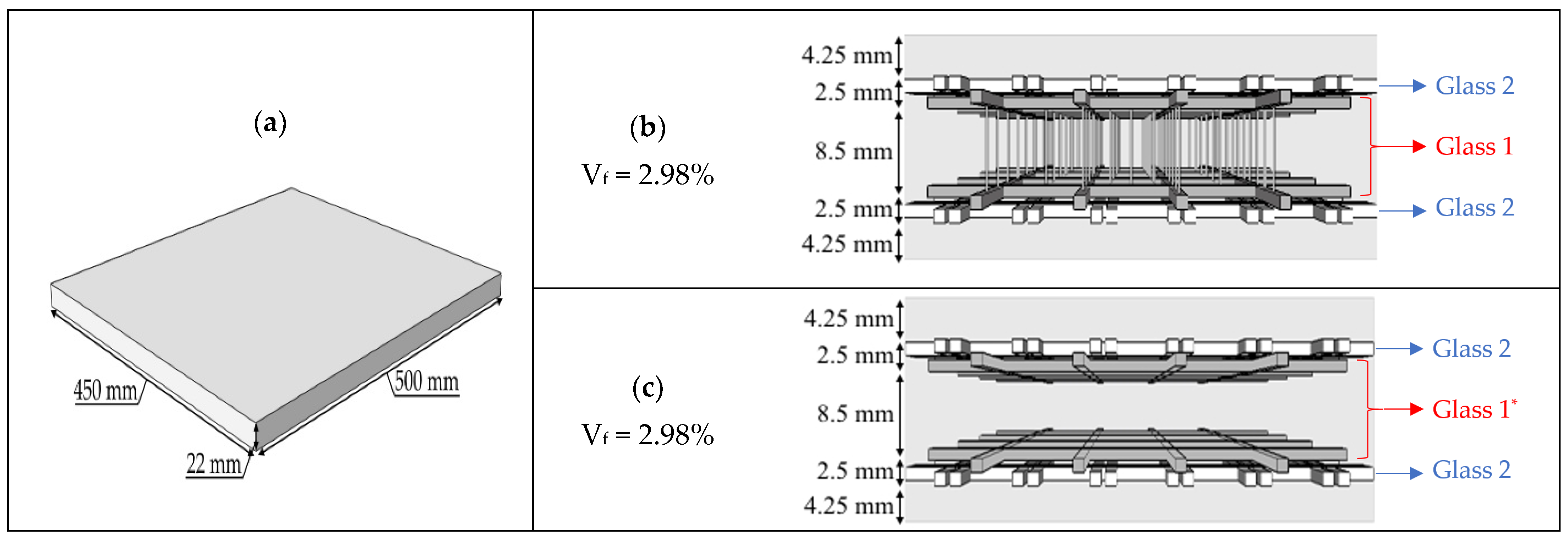
The considered geometry for the TRC plates was 500 mm × 450 mm × 22 mm (length x width x thickness). A schematic is presented in
Figure 2a. In both the 3D (
Figure 2b) and 2D-equivalent (
Figure 2c) alternative, two layers of the Glass2 textile were placed around (one at the top and one at the bottom) one 3D textile. In the 2D-equivalent alternative, the transversal connections of the Glass1 textile were removed (denoted as Glass1* in
Figure 2c) to obtain an identical reinforcement configuration without connections. The fiber reinforcement ratio, V
f, was 2.98% for both configurations. The connection between the Glass2 and Glass1 textiles happened by means of nylon wires.
2.4. TRC Manufacturing Process
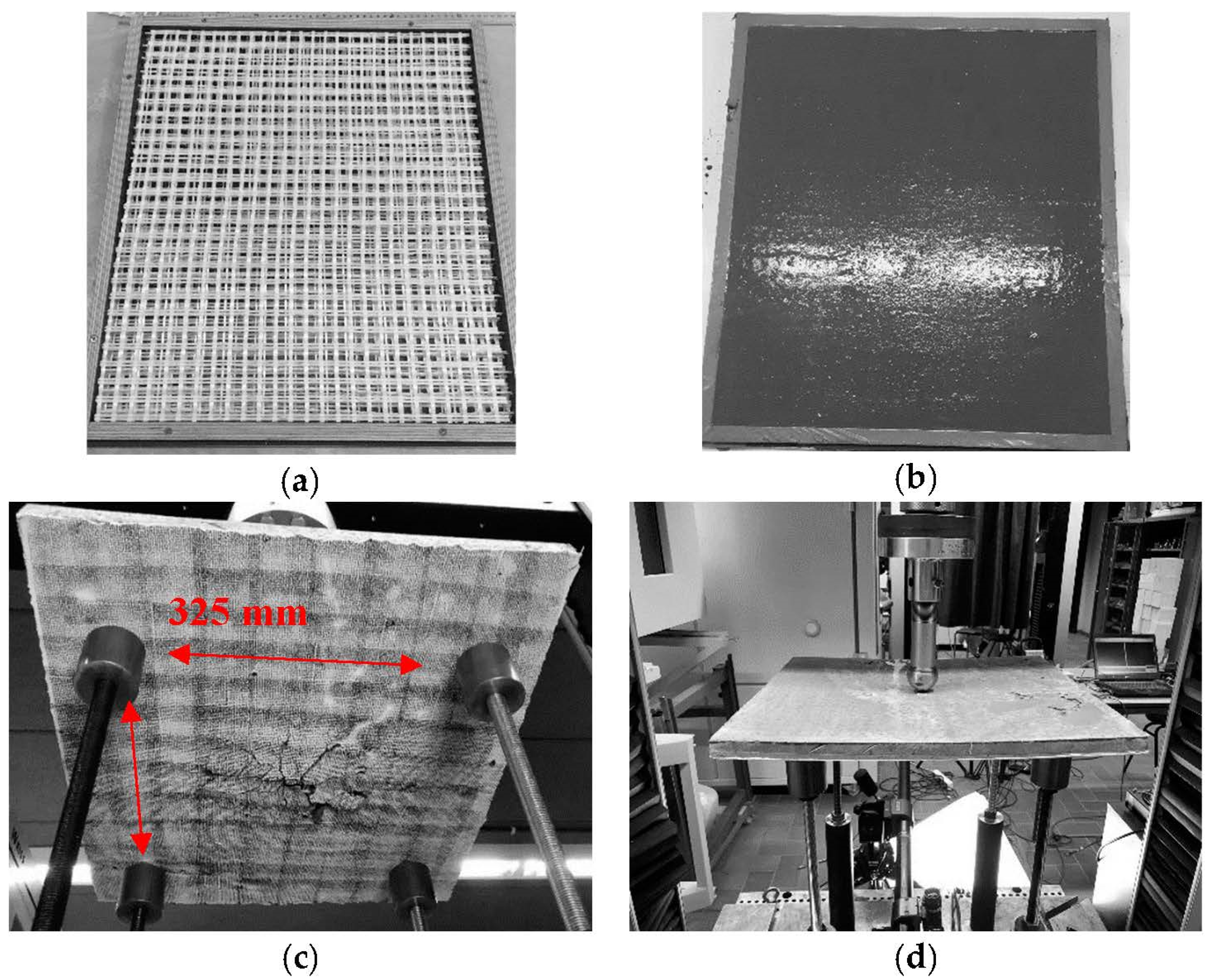
All the TRC plates were manufactured in individual molds. First, an oil film was applied on the inside of the mold to ease the demolding. Secondly, the textiles were placed within the mold, and the matrix was subsequently poured until the mold was filled (
Figure 3a,b). Lastly, the mold was sealed and left to cure at room temperature for 28 days. After demolding, a DIC speckle pattern was applied on one side of the plate. Three plates were manufactured for both the 3D and the 2D-equivalent alternatives.
2.5. Experimental Test Setup
The plates were supported in four points by metal spheres placed within a cylinder that blocked the vertical displacement of the plate while allowing it to rotate at the supports (
Figure 3c,d). The load was induced using a metal sphere pushing on a loading coin at the center of the plates. The coin was necessary to avoid local punching shear failure. The specimens were loaded using an Instron 5885H (Instron, Norwood, MA, USA) universal electromechanical test bench at a rate of 2 mm/min. Two DIC cameras (Correlated Solutions Inc, Columbia, SC, USA) monitored the bottom of the samples. The pixel density of the cameras was 2448 pixels by 2048 pixels. The subset size, step size, and strain window size were selected as 21, 7 and 9, respectively. The speckle size varied between 1.75 mm and 2 mm, and the resolution was 0.15 mm/pixel.
3. Numerical Modeling
Numerical models, based on the properties of the constituting materials, are capable to correctly predict the flexural behavior of 2D-equivalent TRCs without transversal connections [
15,
16]. These models were employed in this research study to endorse the experimental results obtained from the 2D-equivalent layup and together served as a benchmark to highlight the potential mechanical influence of 3D TRCs. In this research study, a semi-smeared modeling approach based on [
15] was used, and a short description is given below.
The plates were modeled in numerical software Abaqus using continuum shell elements in combination with a composite layup. Each of the layers (measures in accordance with
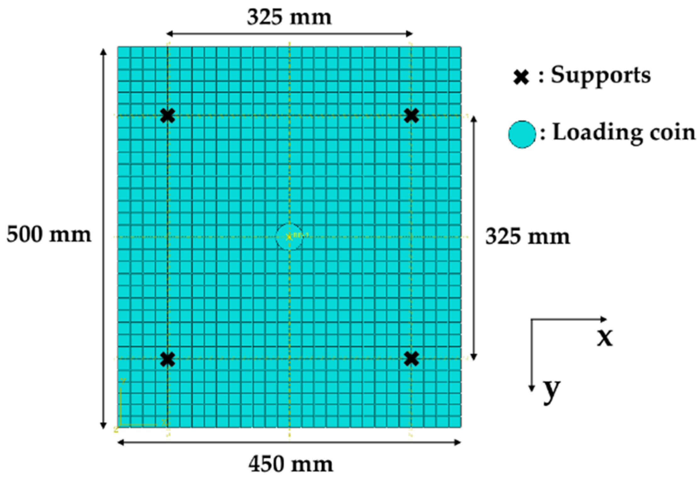
Figure 2c) were given individual (smeared) mechanical properties based on the materials present in the layer (mortar or combination of textiles). Since the subsequent layers had different mechanical properties, the total cross-section could be described as semi-smeared. Meshing was achieved by means of 8-node quadrilateral in-plane shell elements (SC8R), and 32 and 28 mesh elements were present in the 500 mm and 450 mm dimensions of the plate, respectively (see
Figure 4). The supporting conditions were implemented by restricting the vertical (z-direction) displacement of the respective nodes. The vertical displacement was imposed to the centrally located loading coin, which had a hard contact and a frictionless tangential constraint property with the top surface of the plate.
4. Results and Discussion
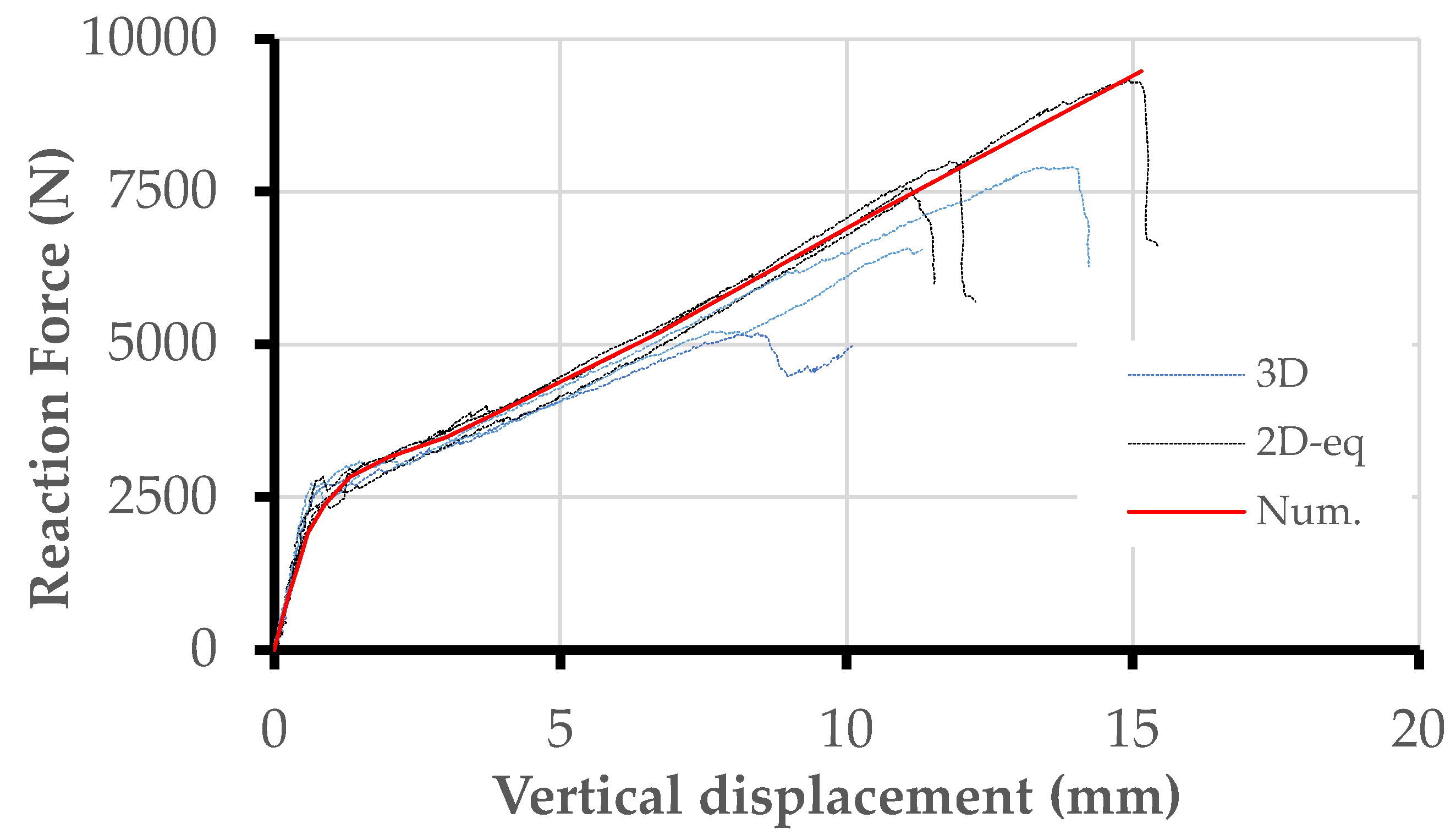
The experimental load–displacement curves of all six plates (three per configuration) as well as the results from the numerical simulations are given in
Figure 5. All loads were obtained directly from the test bench, whereas the displacements were obtained by following a central point in the DIC analysis.
Table 2 presents all the pre- (k1) and post-cracking (k3) slopes (calculated between 2 mm and 8 mm displacement), as well as failure load (F
max), and standard deviations. Lastly,
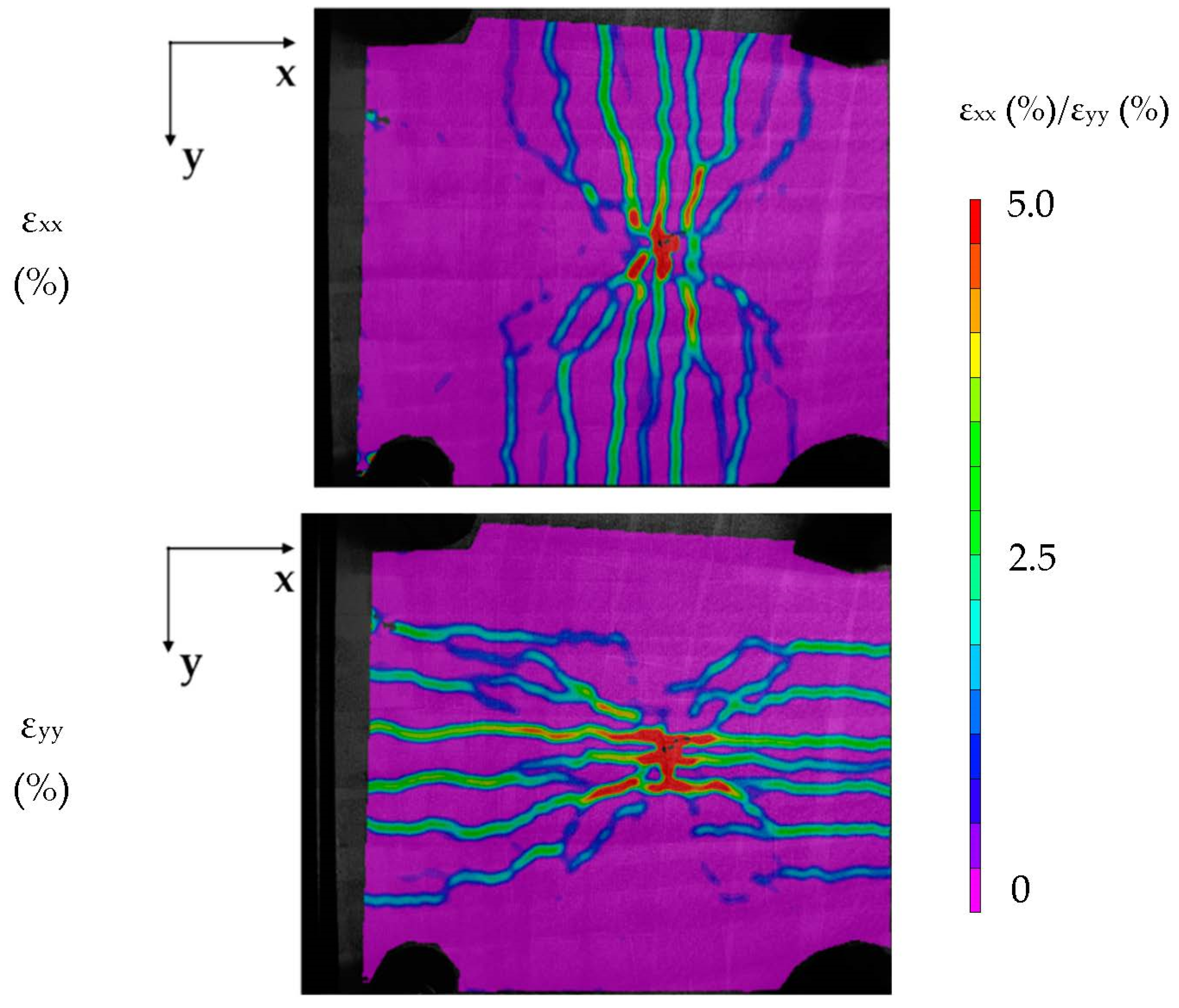
Figure 6 shows the strain-field images obtained from the DIC monitoring of a representative plate at a vertical displacement of 10 mm.
Pre-cracking slope k1 was comparable for the 3D and 2D-equivalent configurations (respectively, 3964 ± 274 N/mm and 3887 ± 195 N/mm). This value was also supported by the numerical simulation (see
Figure 5 and
Table 2). The similarity was expected, since the pre-cracking stage of TRC composites is mainly dominated by the properties of the cementitious matrix, which always remained the same.
In the post-cracking stage, the 2D-equivalent alternative exhibited a marginally improved post-cracking slope compared with the 3D one (respectively, 401 ± 31 N/mm and 451 ± 13 N/mm) but not sufficient to yield conclusive results. At the level of the cracking patterns, both configurations exhibited comparable crack amounts, crack widths, and cracking patterns, as shown for a representative sample in the x- and y-directions in
Figure 6.
The failure of the specimens occurred by means of fiber failure in all samples. Relatively large discrepancies were observed between the three samples of each configuration (see
Figure 5 and
Table 2). It was assumed that, due to the complex stress distribution in bidirectional plates as well as the relatively open reinforcement architecture, the stress transfer between the reinforcement and the matrix within the TRC cross-section might have been suboptimal and the failure subjected to localized phenomena and imperfections.
From these preliminary observations, it could not be concluded that the addition of transversal connections provided any contribution to the mechanical post-cracking slope nor strength in bidirectionally loaded TRC plates. These results were opposite to the observations of unidirectionally loaded beams in bending, where clear post-cracking slope increases of up to 250% were reported for the 3D TRCs compared with the 2D-equivalent TRCs [
13,
14]. It was assumed in the literature that the mechanical contribution of the transversal connections originated from an improved anchorage of the in-plane textiles and was only exhibited in cases where the reinforcement structure was not sufficiently naturally anchored (as was the case in unidirectional bending with limited free end outside the supports).
In this research study, a possible hypothesis was that due to the bidirectional nature of both the stress distribution and the textile mesh, the textiles were sufficiently naturally anchored, without the need for a free-anchorage zone outside the supports. This hypothesis is supported by the fact that the dominant failure mechanism was fiber failure, as opposed to fiber pull-out in unidirectional bending. This would explain why no noticeable differences were observed between the 3D and 2D-equivalent alternatives in bi-directional plates.
At the level of the numerical simulations, the results validated that the semi-smeared, layered modeling approach as described in [
15] was appropriate for the prediction of the macroscopic mechanical behavior of bidirectionally loaded TRC composites. It should be noted, however, that numerically, the implemented failure mechanism always coincided with the breakage of fiber reinforcement.
5. Conclusions
The main objective of this research study was to assess if the improved mechanical anchorage observed in unidirectional-bending applications could also be observed in bidirectional-loading (and thus stress) configurations. For this purpose, TRC plates supported in four points were centrally loaded, inducing a bidirectional-stress configuration in the TRCs. A comparison was drawn between the 3D and 2D-equivalent configurations, geometrically identical and only different in whether they contained transversal connections. The experimental results showed that in case of bidirectionally loaded plates, the post-cracking stiffness increase, observed in the literature on 3D TRCs, could not be replicated. It was assumed that this might have been linked to the improved anchorage of the in-plane textiles in bidirectional compared with unidirectional applications. Additionally, a semi-smeared, layered numerical model was validated for bidirectional-loading configurations.
The observations presented in this research study highlighted the fact that the underlying anchorage mechanism provided by transversal connections in load-bearing TRC sections should be further investigated and understood before potentially including them in the design of TRC elements. Larger, bidirectionally loaded structures as well as other loading/geometrical configurations (arches, floor systems, etc.) remain to be investigated.
Author Contributions
Authors, M.E.K., D.V.H. and T.T.; conceptualization, M.E.K., D.V.H. and T.T.; methodology, M.E.K., D.V.H. and T.T.; investigation, M.E.K.; writing—original draft preparation, M.E.K.; writing—review and editing, D.V.H. and T.T.; funding acquisition, D.V.H. and T.T. All authors have read and agreed to the published version of the manuscript.
Funding
This research study was funded by Agentschap Innoveren en Ondernemen and was part of a larger SBO project (CeComStruct grant number: IWT697). The authors would like to thank all involved parties that made this research study possible.
Institutional Review Board Statement
Not applicable.
Informed Consent Statement
Not applicable.
Data Availability Statement
The data presented in this study are available on request from the corresponding author.
Conflicts of Interest
The authors declare no conflict of interest.
References
- Peled, A.; Mobasher, B.; Bentur, A. Textile Reinforced Concrete, 1st ed.; CRC Press: Boca Raton, FL, USA, 2017. [Google Scholar]
- Naaman, A.E. Textile Reinforced Cement Composites: Competitive Status and Research Directions Ferrocement. In International RILEM Conference on Material Science; RILEM Publications: Paris, France, 2010; pp. 3–22. [Google Scholar]
- Triantafillou, T.; Papanicolaou, C.G. Shear Strengthening of Reinforced Concrete Members with Textile Reinforced Mortar (TRM) Jackets. Mater. Struct. 2006, 39, 93–103. [Google Scholar] [CrossRef]
- Brückner, A.; Ortlepp, R.; Curbach, M. Anchoring of Shear Strengthening for T-Beams Made of Textile Reinforced Concrete (TRC). Mater. Struct. 2008, 41, 407–418. [Google Scholar] [CrossRef]
- Si Larbi, A.; Agbossou, A.; Hamelin, P. Experimental and Numerical Investigations about Textile-Reinforced Concrete and Hybrid Solutions for Repairing And/or Strengthening Reinforced Concrete Beams. Compos. Struct. 2013, 99, 152–162. [Google Scholar] [CrossRef]
- Verbruggen, S.; Remy, O.; Wastiels, J.; Tysmans, T. Stay-in-Place Formwork of TRC Designed as Shear Reinforcement for Concrete Beams. Adv. Mater. Sci. Eng. 2013, 2013, 648943. [Google Scholar] [CrossRef] [Green Version]
- Tysmans, T.; Adriaenssens, S.; Cuypers, H.; Wastiels, J. Structural Analysis of Small Span Textile Reinforced Concrete Shells with Double Curvature. Compos. Sci. Technol. 2009, 69, 1790–1796. [Google Scholar] [CrossRef]
- Scholzen, A.; Chudoba, R.; Hegger, J. Thin-Walled Shell Structures Made of Textile-Reinforced Concrete. Struct. Concr. 2015, 16, 115–124. [Google Scholar] [CrossRef]
- Verwimp, E.; Tysmans, T.; Mollaert, M.; Berg, S. Experimental and numerical buckling analysis of a thin TRC dome. Thin-Walled Struct. 2015, 94, 89–97. [Google Scholar] [CrossRef]
- Cuypers, H.; Wastiels, J. Analysis and Verification of the Performance of Sandwich Panels with Textile Reinforced Concrete Faces. J. Sandw. Struct. Mater. 2011, 13, 589–603. [Google Scholar] [CrossRef]
- Vervloet, J.; Van Itterbeeck, P.; Verbruggen, S.; El Kadi, M.; De Munck, M.; Wastiels, J.; Tysmans, T. Experimental investigation of the buckling behaviour of Textile Reinforced Cement sandwich panels with varying face thickness using Digital Image Correlation. Constr. Build. Mater. 2018, 194, 24–31. [Google Scholar] [CrossRef]
- Helbig, T.; Rempel, S.; Unterer, K.; Kulas, C.; Hegger, J. Fuß- und Radwegbrücke aus Carbonbeton in Albstadt-Ebingen. Die weltweit erste ausschließlich carbonfaserbewehrte Betonbrücke. Beton-Und Stahlbetonbau 2016, 111, 676–685. [Google Scholar] [CrossRef]
- Haik, R.; Peled, A.; Gohil, U.; Gries, T. 3D Fabrics as reinforcement for Cement-Based Composites. In Proceedings of the 3rd All Russian Conference on Concrete and Reinforced Concrete, Moscow, Russia, 12–16 May 2014; Volume 3, pp. 206–217. [Google Scholar]
- El Kadi, M.; Tysmans, T.; Verbruggen, S.; Vervloet, J.; De Munck, M.; Wastiels, J.; Van Hemelrijck, D. Experimental study and benchmarking of 3D textile reinforced cement composites. Cem. Concr. Compos. 2019, 104, 103352. [Google Scholar] [CrossRef]
- El Kadi, M.; Tysmans, T.; Verbruggen, S.; Wastiels, J.; Vervloet, J.; De Munck, M.; Van Hemelrijck, D. A layered-wise, composite modelling approach for fibre textile reinforced cementitious composites. Cem. Concr. Compos. 2018, 94, 107–115. [Google Scholar] [CrossRef]
- Chudoba, R.; Sharei, E.; Senckpiel-Peters, T.; Schladitz, F. Numerical modeling of non-uniformly reinforced carbon concrete lightweight ceiling elements. Appl. Sci. 2019, 9, 2348. [Google Scholar] [CrossRef] [Green Version]
| Publisher’s Note: MDPI stays neutral with regard to jurisdictional claims in published maps and institutional affiliations. |
© 2022 by the authors. Licensee MDPI, Basel, Switzerland. This article is an open access article distributed under the terms and conditions of the Creative Commons Attribution (CC BY) license (https://creativecommons.org/licenses/by/4.0/).

