Abstract
In the present work, fatigue crack tip shielding influence is assessed via two full-field optical techniques which are thermoelastic stress analysis and digital image correlation. Two different crack tip field models (CJP and Muskhelishvili) were combined with experimental data from both optical techniques to determine the ΔKeff. The crack tip fields were measured on an aluminium alloy (7050-T6) specimen during fatigue crack growth testing for different R-ratios. The obtained results agree well in terms of ΔKeff showing a variation in ΔK as the R-ratio changes. Hence, the ability of both techniques and crack tip field models to measure effective fatigue crack driving forces is highlighted.
1. Introduction
The application of fracture mechanics concepts to the analysis of fatigue cracks has allowed the addressing of these kinds of problems at a deeper perspective and therefore clarified some fatigue crack growth issues which have led to better and safer designs. Nevertheless, the crack closure phenomenon is one of the most controversial topics in this fatigue assessment approach due to the measurement of the opening/closure load, and hence, the quantification of the effective fatigue crack driving force for fatigue advance [1].
This study addresses the fatigue crack propagation for different stress ratios using two modern optical techniques such as thermoelastic stress analysis (TSA) [2] and digital image correlation (DIC) [1,3] to contribute to a better understanding of fatigue crack propagation mechanics.
TSA, which is based on the thermoelastic effect, seems to offer a direct means of effective ΔK determination since it provides the specimen response during the cyclic loading and hence the cyclic strain at the crack tip. Nonetheless, beyond the presumed ability of that technique to take into account the closure effect, most of the conducted works using TSA for effective crack tip stress intensity determination are based on the analysis of thermoelastic images [4,5,6,7,8]. In the present paper, both optical techniques are employed together with different analytical crack tip fields’ descriptions to assess the role of the plasticity-induced crack tip shielding during fatigue crack propagation on Al7050-T6 aluminium alloy and for the different stress ratios of 0.1 and 0.5. Results in terms of ΔK show the ability of both techniques to determine the crack tip shielding influence during fatigue crack growth.
2. Fundamentals of TSA and DIC
Thermoelastic stress analysis is a non-invasive optical technique that provides full-field stress maps through the analysis of temperature changes on a solid surface as a consequence of a cyclic load. The classical thermoelastic theory states that the occurred temperature change at a solid surface because of a cyclic loading is directly related to the first stress invariant range as displayed in Equation (1) [2].
where K is a the thermoelastic calibration constant depending on the coefficient of thermal expansion α, the density ρ and the constant pressure heat capacity Cp.
DIC is a full-field optical technique measuring the 2D or 3D displacement field on the surface of a body or mechanical element. Two-dimensional DIC calculates the displacement field through comparing a sequence of images, referred to a reference images, which represent the unloaded or undeformed state. To calculate the displacement at each point, those images are split into facets whose centre is used to determine the displacement value. To correct facets recognition during DIC processing, a stochastic pattern must be generated to univocally identify the same facets for both deformed and undeformed images. Two-dimensional DIC measurements require placing the camera sensor normal to the measured surface to avoid errors during the displacement field measurement (out-of-plane displacements).
3. Muskhelishvili’s Complex Potentials and the CJP Model of TSA and DIC
A plane stress tensor can be expressed in terms of a function called the stress function. In the absence of body forces and under equilibrium conditions, this function can be written as follows:
Under those conditions, it exists a U(x,y) (Airy function) that satisfies the following equation:
Muskhelishvili [9] stated that every biharmonic function U(x,y) may be represented by the two functions φ and χ in terms of a complex variable z = x + iy. Hence, this stress function is given by Equation (4).
In Equation (4), the overbar denotes the conjugate, and R denotes the real part of the complex number. Thus, by combining Equations (3) and (4), the following expression is obtained:
According to Nurse and Patterson [10], complex potentials functions can be expressed as Fourier series as shown in expression 6. In addition, as in Muskhelishvili’s model, the boundary conditions at the crack surfaces were satisfied by a conformal mapping equation [9]. Based on these premises, the following two complex potentials are defined:
where AN, BN, am and bm are complex variables and are used to describe different states of stress. ς represents the complex coordinates of points surrounding the crack tip in the mapping plane.
Finally, the resultant expression for the first stress invariant is presented in Equation (7).
The CJP model is a mathematical model [11] based on Muskhelishvili’s complex potentials [9]. However, in this case, the model considers the effect of the plastic enclave nearest the crack tip along with flanks, which modifies the surrounding crack tip K-field- Hence, the model explicitly incorporates crack shielding effects during fatigue crack propagation and therefore provides a more effective rationalization of fatigue crack driving forces.
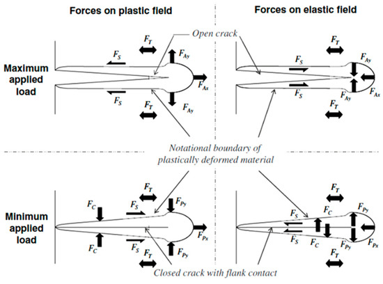
Figure 1 [11] shows a schematic free body diagram illustrating the forces acting at the elastoplastic boundary. In this Figure, FAx and FAy represent the effect of the applied remote load, FPX and FPY represent the interaction force between the plastic enclave and the surrounding elastic field, FT represents the force due to the non-singular stress, Fs the force occurring at the crack flanks and FC the force occurring when the crack is closed prematurely.

Figure 1.
Schematic diagram illustrating the forces acting at the interface of the plastic zone and the surrounding elastic material [11].
According to the CJP model, the crack tip displacement field [11] was characterized as:
where G is the shear modulus, and E and ν are the Young’s modulus and Poisson’s ratio of the material, respectively.
Coefficients A, B, C, E and F are the parameters governing the crack stress field and which are related to different stress intensity factors and non-singular stresses. Thus, by combining these coefficients, the model defines three stress intensity factors, KF which models the mode I stress intensity, KR that models the plasticity-induced retardation effect and KS that provides the effect of crack flanks on the global elastic stress field. In addition, two non-singular stresses are defined along the crack growth and crack opening directions [11].
4. Specimens Preparation and Experimental Methodology
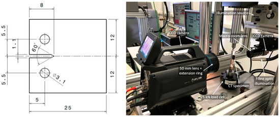
Table 1 shows the mechanical properties for the AA7050-T6 obtained from tensile tests. CT specimens were designed in compliance with the ASTM E647 standard [12], as displayed in Figure 2 (Left), and were tested to a constant amplitude loading holding the maximum load in 600 N. Two fatigue crack growth testings were performed at different stress ratios (0.1 and 0.5).

Table 1.
Mechanical properties for aluminium 7050-T6.

Figure 2.
(Left) Dimensions (mm) of the CT specimen [12] tested in the lab. (Right) Experimental set-up for fatigue testing and data acquisition.
Both specimen surfaces were prepared to enable simultaneous measurements of displacements by DIC and stresses by TSA. The surface used for the DIC study was sprayed with a stochastic black and white pattern, whilst the other surface of the specimen (used for the TSA implementation) was sprayed with a black matt paint in order to increase the surface emissivity.
Fatigue testing was carried out on a servo-hydraulic machine, model MTS 370.02, at the frequency of 10 Hz. DIC images were acquired using a CCD camera (AVT Stingray F-504 B/C) placed perpendicularly to the specimen surface. A macro-zoom lens (MLH-10X EO) was fitted to the camera to increase the spatial resolution. Thus, a spatial resolution of 8.8 μm/pixel was achieved. DIC processing was performed through the commercial software Vic-2D from Correlated Solutions Inc. A 25-pixel facet size and a 1-pixel step were found as reliable values to obtain the crack tip displacement field.
TSA measurements were carried out using a cooled infrared camera model FLIR X6581SC with a 50 mm lens and a 10 mm extension ring providing a spatial resolution of 41 μm/pixel (field of view of 26.2 × 21 mm). IRTA software (developed by DES SLR) was used for TSA processing and, hence, obtained the first stress invariant range from recorded temperature maps. Figure 2 (Right) shows the experimental set-up for fatigue testing.
To calculate the stress intensity factor using both techniques, the multi-point over-deterministic method developed by Sanford and Dally [13] was employed. An annular over the image at the crack tip location was placed, defining an inner radius large enough to avoid including plastic deformation at the crack tip and an outer radius that lies within the region dominated by the elastic stress singularity. In the particular case of TSA, the SIF was calculated by employing Muskhelishvili’s complex potentials, while for the case of DIC, the previously described CJP model was adopted.
5. Results and Discussion
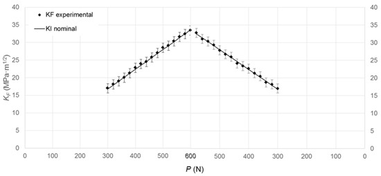
The TSA and DIC data were compared in terms of the stress intensity factor range during the loading cycle for different crack lengths. For the TSA data, these values were directly obtained since the temperature range during a loading cycle was measured and, hence, the stress intensity factor range. However, for the DIC data, the stress intensity factor range was calculated as the difference between the maximum and minimum values of KF (ΔKDIC = KF,max − KF,min). Figure 3 shows the variation of KF along a loading cycle (loading and unloading) for an 8.63 mm crack length at a stress ratio of 0.5. In addition, the theoretical solution provided by the ASTM E647 standard [12] was also displayed to compare experimental and nominal or theoretical values.

Figure 3.
KF along a loading cycle (loading and unloading) calculated through the CJP model for a crack length of 8.63 mm at a stress ratio of 0.5.
Figure 4 displays the obtained values of Knominal, KF,max and KF,min from the DIC data through the CJP model and Kopen from the TSA data as the difference between the measured and the nominal values. For the low stress ratio (R = 0.1), KF,min and Kopen present higher values than Knominal at the minimum applied load. This fact illustrates the ability of the CJP and Muskhelishvili models to infer the shielding effect due to the premature crack closure. Nonetheless, this effect was not observed at the higher stress ratio (R = 0.5), where KF,min and Kopen are equal to the minimum applied load. Authors note that CJP model SIFs cannot be inferred from TSA data since the first stress invariant range is not enough to reproduce the shielding effects on the global stress field according to the CJP model. However, due to the physical nature of TSA, the thermal response of the material (thermoelastic signal first harmonic amplitude) is directly related to the effective fatigue crack driving force [14,15].

Figure 4.
Comparison of experimental and nominal K values at different crack lengths for Al7050-T6 and Al2024-T3 at R = 0.5.
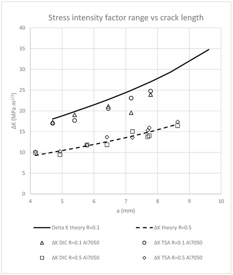
Hence, this is reason why a purely elastic model such as Muskhelishvili’s is able to reproduce crack closure effects. The above statement is supported by Figure 5 where a comparison among ΔK at different stress ratios and for different crack lengths was performed. For the higher stress ratio (0.5), both techniques provide very similar values that agree with the theoretical value. Regarding the lower stress ratio (0.1), experimental ΔK values obtained by DIC and TSA again provide very similar results, but in both cases lower than the nominal value.

Figure 5.
Comparison of the nominal and the effective stress intensity factor ranges obtained by DIC and TSA at different crack lengths for aluminium Al7050-T6 tested at two different stress ratios (0.1 and 0.5).
The above-described results show the ability of both techniques for determining crack tip shielding influence on growing fatigue cracks.
6. Conclusions
Two different optical techniques (TSA and DIC) have been employed to assess the influence of plasticity-induced crack closure on fatigue crack growth. Crack tip shielding influence has been determined in terms of the effective stress intensity factor ranges for different crack lengths and stress ratios (0.1 and 0.5). Experimental data, either TSA or DIC, have been used to infer effective stress intensity through different elastic crack tip field models; for the DIC data, the CJP model has been employed, and for the TSA data, a Muskhelishvili-type model. Results show how both approaches (TSA with a Muskhelishvili-type model and DIC with the CJP model) can provide effective fatigue crack driving forces for fatigue advance for different reasons. In the case of the CJP model, this crack tip field model was specifically formulated to take into account crack tip shielding effects on the global stress field. In the case of the TSA data, the provided effective fatigue crack driving force is attributed to TSA’s physical nature since that technique provides the linear and elastic solid response through the analysis of the first temperature harmonic. The high level of agreement between both data highlights the ability of both approaches to capture plasticity-induced crack tip shielding effects.
Author Contributions
Original idea conceived by F.A.D. and J.M.V.-O.; experimental work supervised by A.J.M.-V., L.A.F.-S. and J.A.A.-L.; experimental test and data processing by A.C.-R.; draft writing by A.C.-R. and F.A.D.; work supervised by E.L.-A. and F.A.D. All authors have contributed to the text with their critical comments, revisions and modifications. All authors have read and agreed to the published version of the manuscript.
Funding
This research was funded by “Ministerio de Economía y Competitividad del Gobierno de España”, grant number MAT2016-76951-C2-1-P and also to ”Junta de Andalucia” through “Proyectos de I+D+i en el Marco del Programa Operativo FEDER Andalucia 2014-2020” grant number 1380786.
Institutional Review Board Statement
Not applicable.
Informed Consent Statement
Not applicable.
Data Availability Statement
The data that support the findings of this study are available from the corresponding author upon reasonable request.
Acknowledgments
Authors want to acknowledge “Ministerio de Economía y Competitividad del Gobierno de España” as well as “Junta de Andalucia” for the financial support without this work could not be performed.
Conflicts of Interest
The authors declare no conflict of interest.
References
- James, M.N. Some unresolved issues with fatigue crack closure—Measurement, mechanism and interpretation problems. In Proceedings of the Ninth International Conference on Fracture, Sydney, Australia, 1–5 April 1997; Pergamon Press: Sydney, Australia, 1997; Volume 5, pp. 2403–2414. [Google Scholar]
- Sutton, M.A.; Orteu, J.J.; Schreier, H.W. Image Correlation for Shape, Motion and Deformation Measurements: Basic Concepts, Theory and Applications; Springer: New York, NY, USA, 2009. [Google Scholar]
- Deal, B.; Grove, A. General Relationship for the Thermal Oxidation of Silicon. J. Appl. Phys. 1965, 36, 3770–3778. [Google Scholar] [CrossRef]
- Thomson, W. On the thermoelastic, thermomagnetic, and pyroelectric properties of matters. Lond. Edinb. Dublin Philos. Mag. J. Sci. 1878, 5, 4–27. [Google Scholar] [CrossRef]
- Stanley, P.; Chan, W.K. The determination of stress intensity factors and crack tip velocities from thermoelastic infrared emissions. Fatigue Eng. Mater. Struct. 1986, 1, 105–114. [Google Scholar]
- Pukas, S.R. Theoretical considerations for determining stress intensity factors via thermoelastic stress analysis. In Stress Analysis by Thermoelastic Technique; SPIE: Bellingham, WA, USA, 1987; Volume 731, pp. 88–101. [Google Scholar]
- Dulieu-Barton, J.M.; Fulton, M.C.; Stanley, P. The analysis of thermoelastic isopachic data from crack tip stress fields. Fatigue Fract. Eng. Mater. Struct. 2000, 23, 301–313. [Google Scholar] [CrossRef]
- Lesniak, J.R.; Bazile, D.J.; Boyce, B.R.; Zickel, M.J.; Cramer, K.E.; Welch, C.S. Stress Intensity Measurement via Infrared Focal Plane Array. Non-Traditional Methods of Sensing Stress, Strain, and Damage in Materials and Structures; ASTM STP 1318; Stress Photonics Inc.: Philadelphia, PA, USA, 1997. [Google Scholar]
- Tomlinson, R.A.; Nurse, A.D.; Patterson, E.A. On determining stress intensity factors for mixed mode cracks from thermoelastic data. Fatigue Fract. Eng. Mater. Struct. 1997, 20, 217–226. [Google Scholar] [CrossRef]
- Muskhelishvili, N.I. Some Basic Problems of the Mathematical Theory of Elasticity; Noordhoff International Publishing: Groningen, The Netherlands, 1977. [Google Scholar]
- Nurse, A.D.; Patterson, E.A. Determination of predominantly mode II stress intensity factors from isochromatic data. Fatigue Fract. Eng. Mater. Struct. 1993, 16, 1339–1354. [Google Scholar] [CrossRef]
- James, M.N.; Christopher, C.J.; Lu, Y.; Patterson, E.A. Local crack plasticity and its influences on the global elastic stress field. Int. J. Fatigue 2013, 46, 4–15. [Google Scholar] [CrossRef]
- ASTM 647; Standard Test Method for Measurement of Fatigue Crack Growth Rates. American Society for Testing and Materials: Philadelphia, PA, USA, 2015.
- Sanford, R.J.; Dally, J.W. A general method for determining mixed-mode stress intensity factors from isochromatic fringe patterns. Eng. Fract. Mech. 1979, 11, 621–633. [Google Scholar] [CrossRef]
- Díaz, F.A.; Patterson, E.A.; Yates, J.R. Assessment of effective stress intensity factors using thermoelastic stress analysis. J. Strain Anal. Eng. Des. 2009, 44, 621–631. [Google Scholar] [CrossRef]
Publisher’s Note: MDPI stays neutral with regard to jurisdictional claims in published maps and institutional affiliations. |
© 2022 by the authors. Licensee MDPI, Basel, Switzerland. This article is an open access article distributed under the terms and conditions of the Creative Commons Attribution (CC BY) license (https://creativecommons.org/licenses/by/4.0/).