Skip to Content
SolarSolar
  • Article
  • Open Access

3 August 2026

Comparative Analysis and Selection of Maximum Power Point Tracking Techniques with Predictive Power Flow Control for Harmonic Mitigation in Renewable-Integrated Smart Grids


,
and
School of Engineering, Computer and Mathematical Sciences, Auckland University of Technology, Auckland 1010, New Zealand
*
Author to whom correspondence should be addressed.

Abstract

The integration of renewable energy into smart grids is beneficial for a sustainable future and the environment. Still, it has challenges such as energy optimisation, environmental conditions and power quality degradation. Existing Maximum Power Point Tracking (MPPT) techniques often focus on tracking efficiency under steady-state conditions, ignoring the impact of real-time variation in environmental conditions and load. The predictive power flow control (PPFC) algorithm is available with one or more fixed MPPT algorithms. No studies have reported on how the choice of MPPT affects PPFC harmonic mitigation. This paper addresses both concerns through a systematic comparative analysis of MPPT techniques integrated with a PPFC method to mitigate harmonics in renewable-integrated smart grid systems. To address this research gap, a comprehensive comparative analysis of various MPPT techniques, such as Perturb and Observe (P&O), Incremental Conductance (INC), Fuzzy Logic Control (FLC), and hybrid Machine Learning (ML) techniques, integrated with PPFC to achieve effective harmonic mitigation in a smart grid environment is conducted. A 3 MW solar farm integrated with a battery storage system is modelled in MTALB/Simulink 2025b under real-time varying conditions, such as environmental and load variations over time in Auckland, New Zealand. The study focuses on key performance parameters such as total harmonic distortion (THD), power loss, stability and efficiency. The Adaptive Neuro-Fuzzy Inference System (ANFIS)-based MPPT controller, integrated with forecast-based power flow control, achieved overall performance by providing higher efficiency (97.5%), effective harmonic mitigation, and enhanced system stability under the nonlinear behaviour of the photovoltaic system. The proposed ANFIS-based system ensured a stable and smooth power output under varying environmental conditions, outperforming conventional and other intelligent MPPT techniques.

1. Introduction

The global transition towards sustainable renewable energy systems (RES) has accelerated the integration of RES into smart electricity grids. Among RES, solar systems have emerged as a leading technology due to their modularity and environmental benefits [1]. In New Zealand, the government’s ambition to achieve 100% renewable electricity by 2030 has triggered large-scale solar investments. Recent projects such as the 271 MW Rangiriri Solar Farm (Genesis Energy, acquired in 2025), the 179 MW Glorit Solar Farm with an integrated battery energy storage system (BESS), and the 130 MW Ruakākā Solar Farm are typical examples. As of October 2025, the national generation grid contains 288 projects totalling 44.3 GW, indicating growth in solar generation capacity. However, the same report highlighted challenges stemming from the solar system’s unpredictability. Solar generation in New Zealand falls below 10% of installed capacity for approximately 60% of the time and exceeds 50% of installed capacity for only 14% of the time. Seasonal mismatches occur when summer generation is 47% higher than winter generation, while peak electricity demand occurs in winter. Furthermore, solar output peaks around 1 pm, which does not align with evening demand peaks [2]. The renewable-integrated smart grid poses challenges not only due to intermittency but also to nonlinearities in load and changes in environmental factors. Traditional control techniques, such as proportional–integral (PI) control and conventional MPPT algorithms, tend to fail under continuously varying load and environmental conditions, which leads to efficiency losses and reduced grid support [3]. The efficiency and continuity of RES depend upon the effectiveness of MPPT techniques, particularly under dynamic environmental factors such as solar irradiance, temperature and wind. This study focuses on hybrid MPPT techniques that combine multiple control algorithms to improve efficiency and extract maximum power from RES [4]. MPPT continuously adjusts the operating point to improve overall system efficiency and extract the maximum power. In a hybrid system, MPPT not only extracts maximum power but also enhances power stability and continuity by enabling solar generation to contribute efficiently when available, making it more suitable for both off-grid and grid-connected applications [5].
In solar energy systems, MPPT is used to track the maximum power point on the nonlinear power–voltage (P–V) and voltage–current (V-I) characteristics of photovoltaic (PV) modules. The output power of PV systems varies with changes in solar irradiance and temperature, leading to continuous shifts in the maximum power point (MPP) [6]. MPPT techniques regulate the duty cycle of DC–DC converters to adjust the operating voltage of PV panels and increase power extraction. Traditional methods such as Perturb and Observe (P&O) and Incremental Conductance (InC) are widely used due to simplicity. However, they have limitations from oscillations around the MPP and reduced performance under rapidly changing environmental conditions [7]. Power stability and continuity by enabling solar generation to contribute efficiently when available, making it more suitable for both off-grid and grid-connected applications [8].
Selecting an MPPT technique for RES is challenging due to the diverse operational characteristics and dynamic behaviours of RES sources. In PV systems, the maximum power point depends on irradiance and temperature. Wind energy systems are governed by a highly nonlinear relationship between wind speed and output power. This leads to rapid and unpredictable fluctuations, making MPPT design more complex. This variation causes fluctuations in power generation, making it difficult to meet load demand and maintain power quality, particularly with respect to harmonic distortion and continuity. To address these challenges, MPPT is essential in RES [9]. Advancements in MPPT are required for the following reasons.
  • Maximisation of energy extraction: MPPT ensures that solar systems always operate at their optimal point and improves the overall efficiency of the system.
  • Handling the intermittency of RES: MPPT plays a crucial role in handling variation in environmental conditions.
  • Improved hybrid coordination: In an RES, MPPT helps in maintaining generation and demand with the help of power sharing in solar and energy storage systems. It also helps to compensate for power fluctuations and maintain system continuity during changes in environmental factors.
Despite the importance of MPPT in hybrid RES, it faces several challenges, including variable and non-uniform operating conditions, multiple local maxima, and coordination among multiple sources [10].

Literature Survey

  • Raja and A Thangaraj [11] proposed a Binary Waterwheel Plant Optimisation (BWPO) combined with a Temporal Inductive Path Neural Network (TIPNN) to improve energy management in a grid-connected PV–battery system. The main objective of the study was to minimise total harmonic distortion, reduce energy cost and improve system performance. They achieved a low THD of 1.3%, a Levelised Cost of Energy (LCOE) of $0.059/kWh, and a net present cost (NPC) of $700,500.84, with an overall system efficiency of 98%. The BWPO-TIPNN system is highly complex, requiring extensive parameter tuning and significant computational resources, which may limit its practical deployment in real-time industrial applications.
  • Latreche et al. [12] developed a DC microgrid power management system integrating PV arrays with a Hybrid Energy Storage System (HESS) combination of batteries and supercapacitors. They compared three MPPT techniques, P&O, INC, and FLC, under varying irradiance conditions. Their proposed technique controlled the DC-bus voltage stability at 48 V and ensured power balance, with supercapacitors handling fast transients and batteries managing steady-state variations. The study focused on DC-bus voltage regulation and power sharing, but not on power quality challenges.
  • Varun Sai et al. [13] proposed two novel MPPT techniques, an Improved Adaptive Reference Voltage (IARV) for PV systems and a Searching Space Minimisation-based Artificial Bee Colony (SSM-ABC) for wind-driven Doubly Fed Induction Generators (DFIG). The study focused on reducing inter-harmonics in a grid-connected hybrid renewable energy system. The results demonstrated that the IARV MPPT achieved 99.09% tracking efficiency with a settling time of 14.5 ms, while the SSM-ABC reduced steady-state oscillations to 0.001 rad/s. The proposed system reduced average inter-harmonic content by 32.19% compared to a conventional P&O-based system.
  • Naima et al. [14] introduced a novel MPPT control technique combining a Modified Finite Control Set Model Predictive Control (MFCS-MPC) with an adaptive P&O algorithm. The study focused on improving power quality, stability, and dynamic performance in grid-connected PV systems. The simulation results for the study showed a THD of 1.22%, which is 6% lower than conventional P&O, a 35% improvement in tracking response time, and a 28% reduction in overshoot. The proposed method also reduced switching losses by 15% through a weighted cost function.
This paper addresses existing research gaps in smart grid integration, including intermittency, uncertainty modelling, demand response, harmonics, and instability [15]. A comparative analysis of hybrid and intelligent MPPT methods is conducted, including PSO–P&O, FLC, ANN, and an ANFIS-based MPPT approach. The performance of the MPPT techniques is evaluated under real-time environmental and load conditions. This paper also focuses on implementing a predictive control-based load management technique in the smart grid to examine power quality issues. To examine system behaviours, a MATLAB/Simulink 2025b system was designed under various operating conditions, including variations in solar irradiance, temperature, and load demand. To achieve better performance and validate results, real-time data of variation in environmental conditions and load in Auckland, New Zealand, are used in the MATLAB/Simulink simulation. The case study considers a grid-connected 3 MW PV solar farm integrated with a BESS providing 5 h of storage capacity. The load profile is scaled to reflect actual Auckland demand patterns and realistic operating conditions.

2. Hybrid Renewable Energy System (HRES) Modelling and Design

The global transition towards a decentralised, low-carbon energy system has increased the use of HRES. The HRES, a combination of solar and battery energy storage systems, offers a solution to overcome the intermittency of renewable sources. The integration of HRES with smart grids requires advanced power management [16]. This study focuses on selecting an efficient MPPT controller for a grid-connected PV–battery system. The MPPT controller helps to extract maximum power from RES under varying environmental conditions. Integration of the HRES into the smart grid introduces challenges, including power fluctuations, voltage drops, and harmonic distortion, that increase power system losses and reduce system efficiency. To address this issue, the study uses PPFC. The main contribution of this work is as follows:
  • A novel HRES with an efficient MPPT controller for maximum power extraction.
  • PPFC-based control system for power flow management and harmonic mitigation within a smart grid environment.
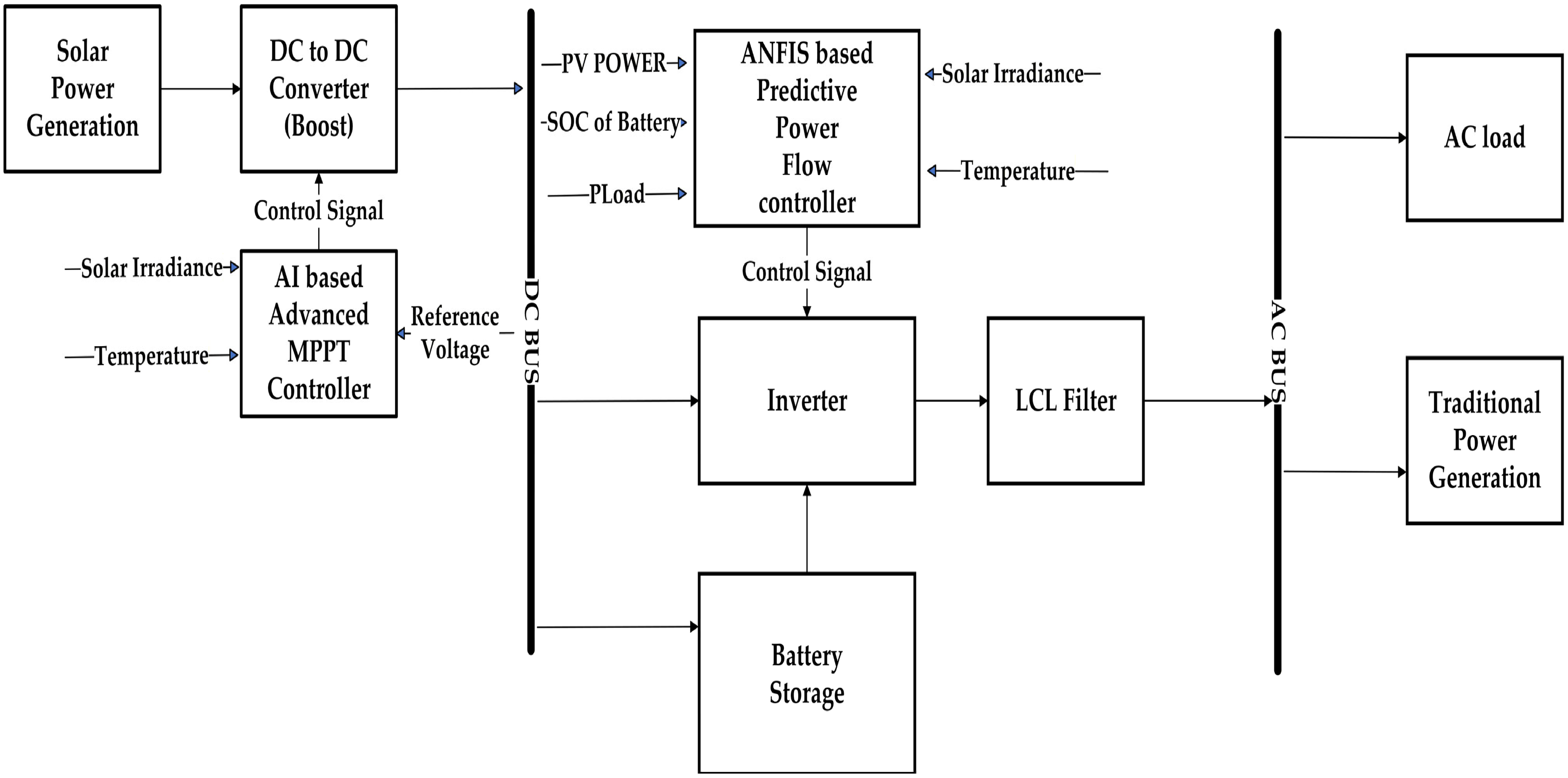
Figure 1 illustrates a block diagram of a PV energy management system integrated with an AI-driven MPPT controller and an ANFIS-based PPFC. The DC–DC boost converter’s duty cycle is optimised by an AI-based MPPT controller that uses irradiance and temperature data to enhance energy extraction. The regulated output is directed to a DC bus, where battery storage is integrated for energy buffering and state of charge (SoC) management. An ANFIS-based PPC intelligently allocates power based on PV output, load requirements, irradiance, temperature, and battery SoC. The inverter then converts the DC-bus power to AC, which is filtered by an LCL filter to reduce harmonics and maintain power quality. Ultimately, the AC bus delivers power to the load.
Figure 1. A block diagram of the proposed system.

2.1. PV System Design

PV systems are among the most promising renewable energy systems. Conventionally, grid-connected PV converters are designed to inject active power into the utility grid [17]. The PV array is modelled using a single-diode equivalent circuit. The current output of the PV module can be expressed as [18]:
I p v =   I p h   I 0 × [ exp ( V p v +   R s × I p v N s × n × V t T )   1 ] V p v +   R s × I p v R s h
where
  •   I P V   = output current of the PV module (A);
  •   I p h   = photocurrent (A);
  •   I o = diode reverse saturation current (A);
  •   V p v = PV output voltage (V);
  •   R s = series resistance (Ω);
  •   N s = number of cells connected in series;
  •   n = diode ideality factor;
  •   R s h = shunt resistance (Ω);
  •   V T = thermal voltage (V). defined as = ( k   ×   T ) q ;
  •   q = electron charge (1.602 × 10⁻¹⁹ C);
  •   T = cell temperature (K);
  •   k = Boltzmann constant (1.381 × 10⁻²³ J/K).
  I p h   is dependent on solar irradiance and temperature, and can be expressed as [19]:
I p h =   [ I s c +   K i × ( T     T r e f ) ] × ( G G r e f )
where
  •   T r e f = reference temperature (25 °C);
  •   T = operating temperature (°C);
  •   K i = temperature coefficient of current (A/°C);
  •   I s c = short-circuit current at standard temperature conditions (STC) (A).
I 0 = I 0   r e f × ( T T r e f ) 3 × exp [ ( q × E g n × k ) × ( 1 T r e f 1 T ) ]
where
  •   I 0   r e f = saturation current at STC (A);
  •   E g = semiconductor bandgap energy (~1.12 eV for silicon).
  I 0 r e f = I s c   [ exp ( V o c N s × n V t   r e f ) 1 ]
where
  •   V o c = open-circuit voltage at STC (V);
  •   V T   r e f = thermal voltage at reference temperature (V).
Table 1 shows the simulation parameters for solar generation and the DC-to-DC boost converter.
Table 1. Simulation parameters for solar generation and DC converter [20,21].

2.2. Battery Storage Design [22]

The integration of a BESS with solar power is important due to the intermittent nature of solar generation. The main benefits include energy reliability when solar generation is unavailable, power balance during peak hours, improved power quality by stabilising voltage and frequency, and an uninterrupted power supply in the smart grid.
E b a t = ( P l o a d × t b a c k u p ) ( η b a t × D O D )
where
  •   E b a t = Required battery energy (Wh or kWh);
  •   P l o a d = Load power (W or kW) (800 KW maximum load during peak hour);
  •   t b a c k u p = Backup time (hours);
  •   η b a t = Battery efficiency (0.85);
  •   D O D = Depth of discharge (0.8).
E b a t = ( 800 × 5 ) ( 0.85 × 0.9   ) = 5.2   M W h
The battery capacity   C b a t   in ampere-hours (Ah) can be calculated as:
C b a t = E b a t V b a t
where V b a t represents the battery voltage (900 V).
C b a t = 5.23 × 10 6 900 = 5811   A h

2.3. DC-Link Capacitor Design [23]

The DC-link capacitor plays an important role in maintaining voltage stability and balancing instantaneous power variations between the PV source and the grid-side converter. The DC-link capacitor size is calculated using the energy balance method.
C d c = ( 3 × k × a × V p h × I s h × t ) 0.5 × ( V d c 2 V d c 1 2 )
where
  •   V d c = average DC-link voltage V d c = ( 2 2 3 m ( V L L ) ) ;
  •   C d c = DC-link capacitance (F);
  •   V p h = per-phase inverter voltage (V);
  •   V L L = line-to-line voltages (V);
  •   I s h = inverter phase current (A);
  •   t = transient response time (s);
  •   k = overload factor (1.5);
  •   a = energy variation factor (0.1);
  •   m = modulation index (0.8);
  •   V d c 1 = minimum required DC-bus voltage (V).
C d c = ( 3 × 0.1 × 1.5 × 440 × 2273 × 0.03 ) [ 0.5 × ( 1100 2 1050 2 ) ]     C d c 0.25   F = 250   m F

2.4. Comparison of MPPT Technique

The integration of MPPT in PV–battery systems is essential for optimising energy harvesting and ensuring system continuity. The selection of an appropriate MPPT algorithm is crucial as it directly impacts the total harmonic distortion (THD) and efficiency of the grid-connected system. Traditional MPPT techniques, such as P&O and INC, vary in performance, particularly under rapidly changing atmospheric conditions, which can affect efficiency and increase the THD of the grid [24]. Advanced MPPT methods that continuously adjust to environmental changes can improve energy conversion efficiency and reduce THD. The choice of MPPT not only affects the efficiency of the PV system but also plays an important role in ensuring compliance with grid standards and enhancing the quality of power delivered to the grid [25].

2.4.1. Perturb and Observe (PO) [26]

The Perturb and Observe (P&O) algorithm is a simple, widely used MPPT technique that tracks the MPP by periodically perturbing the PV voltage and observing the resulting change in power. The power variation is given by:
    Δ P = P ( k ) P ( k 1 )
If Δ P > 0 the controller continues the perturbation in the same direction. Otherwise, it reverses the perturbation direction. The algorithm continuously adjusts the boost converter duty cycle until the operating point reaches the MPP. The main advantages of the P&O method include simple implementation, low computational complexity, and low cost. However, it suffers from steady-state oscillations around the MPP, slower response under rapidly changing irradiance conditions, and possible tracking errors during sudden environmental variations or partial shading.

2.4.2. Incremental Conductance (INC) [27]

The INC MPPT controller determines the MPP by utilising the slope of the PV power–voltage characteristic. The INC algorithm evaluates the relationship between incremental (ΔIV) and instantaneous (−I/V) conductance enabling accurate tracking under rapidly changing irradiance and temperature conditions. The algorithm assumes the slope of the PV power curve is zero at the MPP. Since PV power is expressed as P = V I , the derivative of power with respect to
  Δ V Δ I = V I
I f     Δ V Δ I > V I
The operating point lies to the left of the MPP, and the PV voltage must be increased. If the operating point is located to the right of the MPP, then the PV voltage must be decreased. The controller continuously measures the PV current and voltage, calculates their increments, and adjusts the boost converter duty cycle until the MPP condition is satisfied.
  Δ V Δ I < V I

2.4.3. Particle Swarm Optimisation (PSO) [28]

PSO is a population-based optimisation algorithm introduced by Kennedy and Eberhart. It is inspired by the collective behaviour of bird flocks and fish schools. In a PV system, the output power continuously changes with variations in solar irradiance and temperature. Therefore, the PV array must operate at the MPP to extract the maximum possible power. PSO provides an effective MPPT approach by searching for the duty cycle that maximises power output. In PSO, a population of particles represents candidate solutions that move through the search space to locate the optimal solution. Each particle updates its position based on its own best experience (pbest) and the best solution found by the swarm (gbest). The particle velocity and position are updated using the equations below:
v i { k + 1 } = ω v i k + c 1 r 1 × ( p b e s t i x i k ) + c 2 r 2 × ( g b e s t x i k )
x i { k + 1 } = x i k + v i { k + 1 }  
where:
  x i = particle position;
  v i = particle velocity;
  ω = inertia weight;
  c 1 = cognitive coefficient;
  c 2 = social coefficient;
  r 1 and r 2 = random numbers between 0 and 1.
During each iteration, particles update their velocities and positions, gradually moving toward the optimal solution. The process continues until a stopping criterion is met or the best solution is found. The main advantage of PSO-based MPPT is its ability to perform a global search. PSO can effectively locate the global MPP under partial shading conditions, where multiple local power peaks exist. PSO offers fast convergence, high tracking accuracy, and improved efficiency in rapidly changing environmental conditions.

2.4.4. Hybrid Perturb and Observe–Particle Swarm Optimisation (PO-PSO) [29]

The hybrid PO-PSO MPPT algorithm integrates the strengths of both methods to enhance PV system efficiency, particularly under dynamic environmental conditions. The PO algorithm is effective under stable conditions due to its direct tracking capability, enabling quick convergence to the MPP. However, it struggles in fluctuating environments, where the PSO algorithm excels by broadly exploring the solution space. The hybrid approach dynamically switches between the PO and PSO methods based on the magnitude of changes in power output, thereby mitigating the limitations of each method. The working of the hybrid PO-PSO algorithm involves several key steps. First, the PSO algorithm initialises particles representing potential duty cycles. The PSO performs a global search to identify the region of the maximum power point by updating particle velocity and duty cycle as:
  V n e w =   w   ×   v   +   c 1   ×   r a n d ( ) ×   ( p b e s t     d ) +   c 2   ×   r a n d ( ) ×   ( g b e s t     d )
d n e w = d + v n e w
where v is the particle velocity, d is the current duty cycle, w is the inertia weight, and c1 and c2 are the cognitive and social coefficients, respectively. The rand() function introduces stochastic behaviour to enhance exploration. This iterative process enables the algorithm to search globally for the optimal operating point.
When the power variation becomes sufficiently small, indicating that the system is close to the MPP, the algorithm transitions to the PO phase for fine-tuning. In this phase, the duty cycle is adjusted based on the change in power as follows:
I f   P n e w >   P o l d d   =   d   +   Δ d
I f   P n e w < P o l d   d = d Δ d
This local adjustment helps minimise steady-state oscillations and ensures precise tracking of the MPP. The decision to switch between PSO and PO is based on the magnitude of power variation, allowing the hybrid controller to exploit PSO’s global search capability during large deviations and PO’s rapid convergence near the steady state.
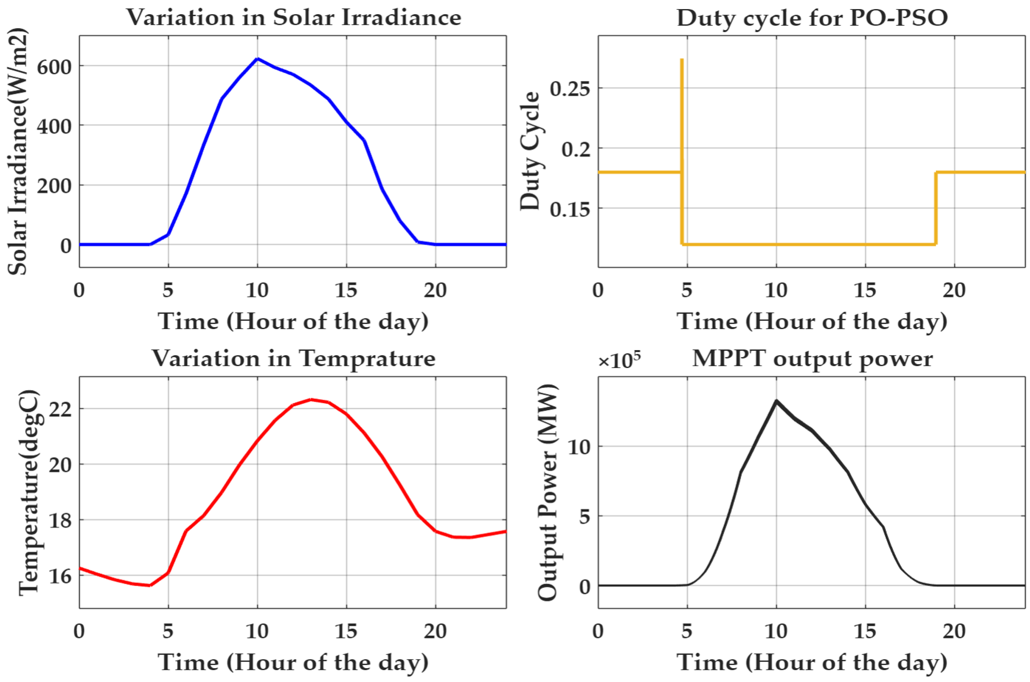
Figure 2 shows the variation in environmental factors, solar irradiance, and temperature on 28 December 2025, with the data taken from NASA POWER [30]. The figure also presents changes in output power and duty cycle for the hybrid PO/PSO MPPT technique under varying environmental conditions.
Figure 2. The variation in environmental factors and output power over the course of the day.

2.4.5. ANFIS-Based MPPT Controller [31]

The Adaptive Neuro-Fuzzy Inference System (ANFIS) is a hybrid intelligent system that integrates the learning capabilities of artificial neural networks with the reasoning capabilities of fuzzy logic. In the context of solar PV systems, ANFIS is employed to enhance the performance of MPPT controllers. The ANFIS architecture consists of five layers, each serving a specific function in transforming input variables (such as solar irradiance and temperature) into desired outputs (such as the optimal duty cycle for a DC-DC converter). In the first layer, the inputs are fuzzified using membership functions that determine the degree to which each input belongs to a fuzzy set. For instance, if the inputs are solar irradiance (x) and temperature (y), the membership functions could be defined as high or low. The output of this layer is given by the equations
O ( 1 , i ) = μ A i ( x ) ,     a n d   O ( 1 , i ) = μ B i ( y )  
where
  •   μ A i ( x ) = membership value of input x;
  •   μ B i ( y ) = membership value of input y.
The second layer computes the firing strengths of the fuzzy rules using the AND operator, yielding outputs.
The third layer normalises these firing strengths, and the fourth layer applies the consequent parameters of the rules to compute the output. Finally, the fifth layer aggregates the outputs to produce the result, which is the control signal for the
O u t p u t = ( w ¯ 1 × f 1 ) + ( w ¯ 2 × f 2 )
where
  •   f 1 , f 2 = output of each rule;
  •   w ¯ 1 ,   w ¯ 2 = normalised firing strength.
The fuzzy inference mechanism is typically based on a first-order Sugeno model, where rules are formulated as
R u l e   1 : I f   x   i s   A 1   a n d   y   i s   B 1 ,   t h e n   f 1 = p 1 × x + q 1 × y + r
R u l e   2 : I f   x   i s   A 2   a n d   y   i s   B 2 ,   t h e n   f 2 = p 2 × x + q 2 × y + r 2
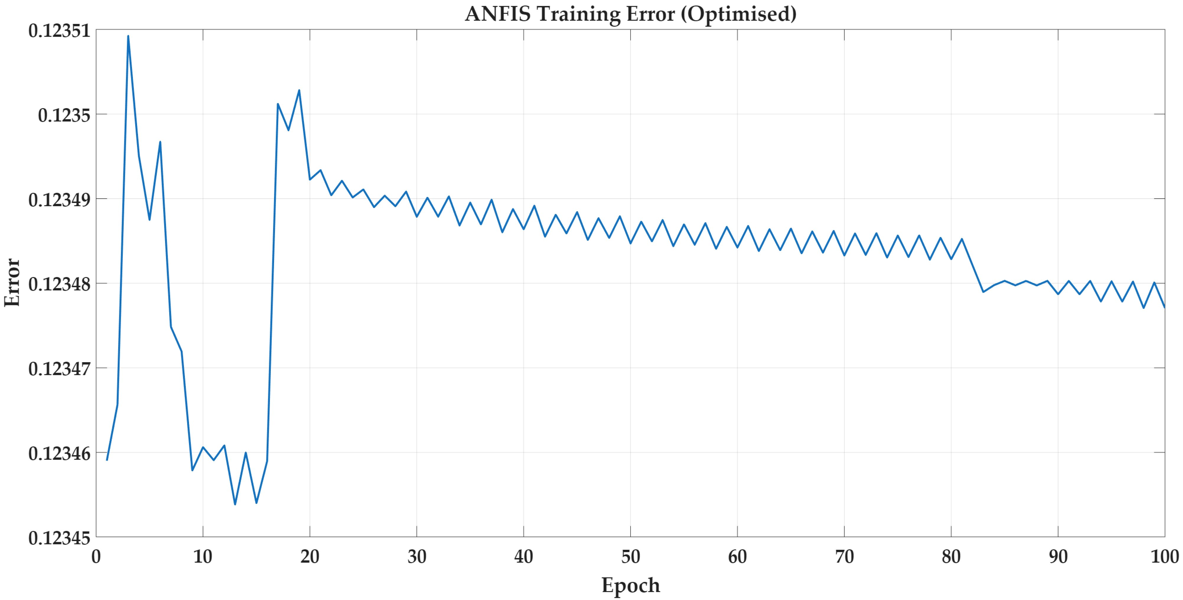
Here, p1, p2, q1, and q2 are parameters determined during training, enabling the ANFIS to optimise the DC-DC converter’s duty cycle and ensure maximum power extraction from the PV system. Figure 3 shows the training error of the ANFIS model over 100 epochs. Initially, the error fluctuates, indicating parameter adjustment during the early learning stages. As training progresses, the error gradually stabilises, demonstrating the convergence of the model. The nearly constant error at later epochs confirms that the ANFIS has learned the input–output mapping effectively for MPPT control.
Figure 3. ANFIS training error convergence curve.

2.4.6. Fuzzy Logic-Based MPPT Controller [32]

This section discusses the Fuzzy Logic Control (FLC) method for MPPT in PV systems, particularly focusing on its application with a boost converter under varying environmental conditions such as temperature and irradiance. The FLC MPPT algorithm is designed to optimise PV panel performance by ensuring they operate at their MPP, which is crucial for maximising energy yield. The working principle of the FLC MPPT controller involves monitoring changes in PV panel power and voltage. The algorithm uses a rule-based approach, with the inputs being the error (E) and the change in error (CE), which are processed through a predefined rule table to determine the boost converter’s output duty cycle (D). The equations governing the FLC MPPT can be expressed as follows:
  E   =   P ( k )   P ( k 1 )
where P(k) is the present power and P(k − 1) is the previous power of the PV system. The change in error is defined as:
C E   =   E ( k )   E ( k 1 )
These two inputs provide information about the direction and rate of movement of the operating point on the power–voltage (P–V) curve.
The fuzzy inference control system utilises a predefined rule base (rule table) to determine the appropriate control action. The rules are typically structured as:
  • IF E is Positive AND CE is Positive → Increase duty cycle (D);
  • IF E is Positive AND CE is Negative → Decrease duty cycle (D);
  • IF E is Negative AND CE is Positive → Decrease duty cycle (D);
  • IF E is Negative AND CE is Negative → Increase duty cycle (D).
These rules help the system toward the MPP by adjusting the operating voltage in the correct direction. Based on the fuzzy decision, the duty cycle of the boost converter is updated as:
D ( k ) =   D ( k 1 ) +   Δ D ( k )
where D(k) is the updated duty cycle and ΔD(k) is the output obtained from the fuzzy inference system.
The duty cycle directly controls the boost converter’s switching operation, thereby regulating the PV output voltage and ensuring convergence toward the MPP. By continuously adjusting the duty cycle in response to changing environmental conditions, the FLC-based MPPT achieves fast dynamic response and minimises steady-state oscillations.
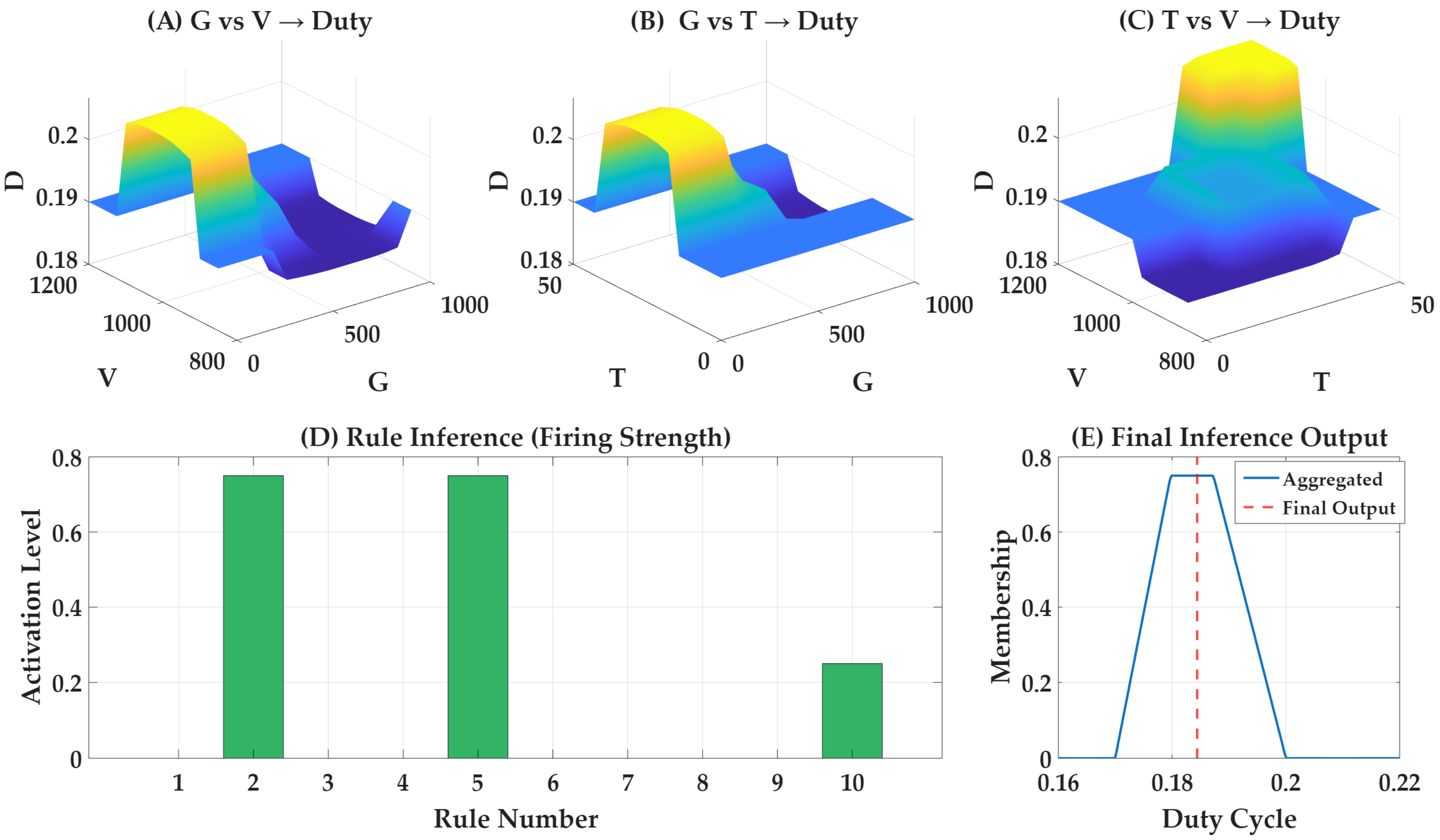
Figure 4 shows the fuzzy MPPT controller behaviour through rule surfaces and inference analysis. The 3D surfaces (A-C) show the ANFIS model’s nonlinear mapping capability, with the duty cycle adjusted to environmental conditions to ensure accurate maximum power point tracking. The rule-firing plot (D) shows that multiple fuzzy rules are simultaneously activated, with varying degrees of activation. The distribution of activation levels indicates that the fuzzy system effectively selects the most relevant rules, improving accuracy and reducing unnecessary computations. The aggregated output curve (E) represents the aggregated membership function and the final defuzzified duty cycle value. It confirms that the fuzzy controller produces a smooth, precise, and stable control signal for MPPT operation.
Figure 4. ANFIS-based MPPT duty cycle generation: (A) duty cycle (D) variation with G and V, (B) D variation with G and T, (C) D variation with T and V, (D) fuzzy rule inference showing firing strength distribution, and (E) final defuzzified output.

2.4.7. Neural Network-Based MPPT Controller [33]

The neural network-based MPPT controller proposed in this study utilises a PV module model to derive an analytical, iterative approach to determining the maximum power point (MPP) voltage and estimating irradiance. The core of the methodology involves using the neural network model’s output current expression to compute the gradient of the power–voltage (P-V) curve with respect to voltage. This gradient information is essential for efficiently guiding the MPPT algorithm towards the optimal operating point. The key equation derived from the neural network model can be expressed in a word-friendly format as follows:
  • Output Current (I): The current output of the neural network model is a function of the MPP voltage (Vmpp), and f(.) is the nonlinear function approximated by the neural network model. This relationship can be represented as:
  I = f (   V m p p ,   G , T )
  • The condition for maximum power point tracking is obtained by differentiating the power with respect to voltage and setting it equal to zero. The resulting gradient expression is:
d P d V = I + V × ( d I d V )
where dI/dV represents the derivative of the current with respect to voltage. This derivative is not computed analytically from the PV model but is instead directly obtained from the neural network representation, thereby simplifying the computation. The MPPT algorithm updates the operating voltage iteratively according to the following rule:
V n e w =   V o l d +   α   ×   ( d P d V )
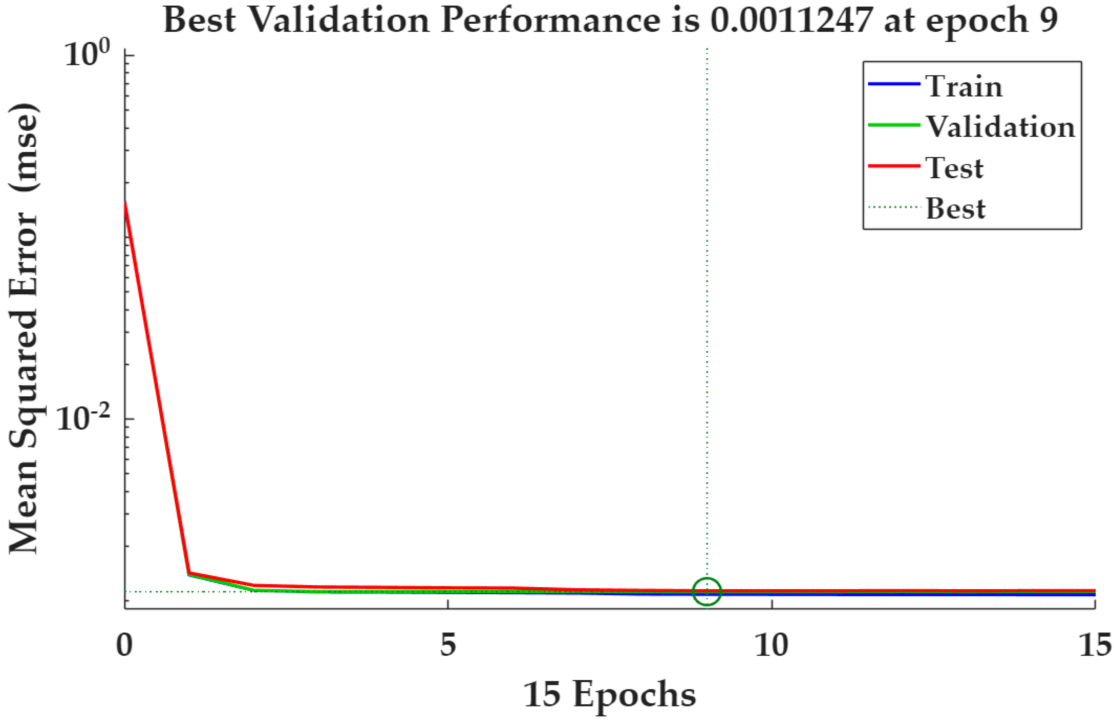
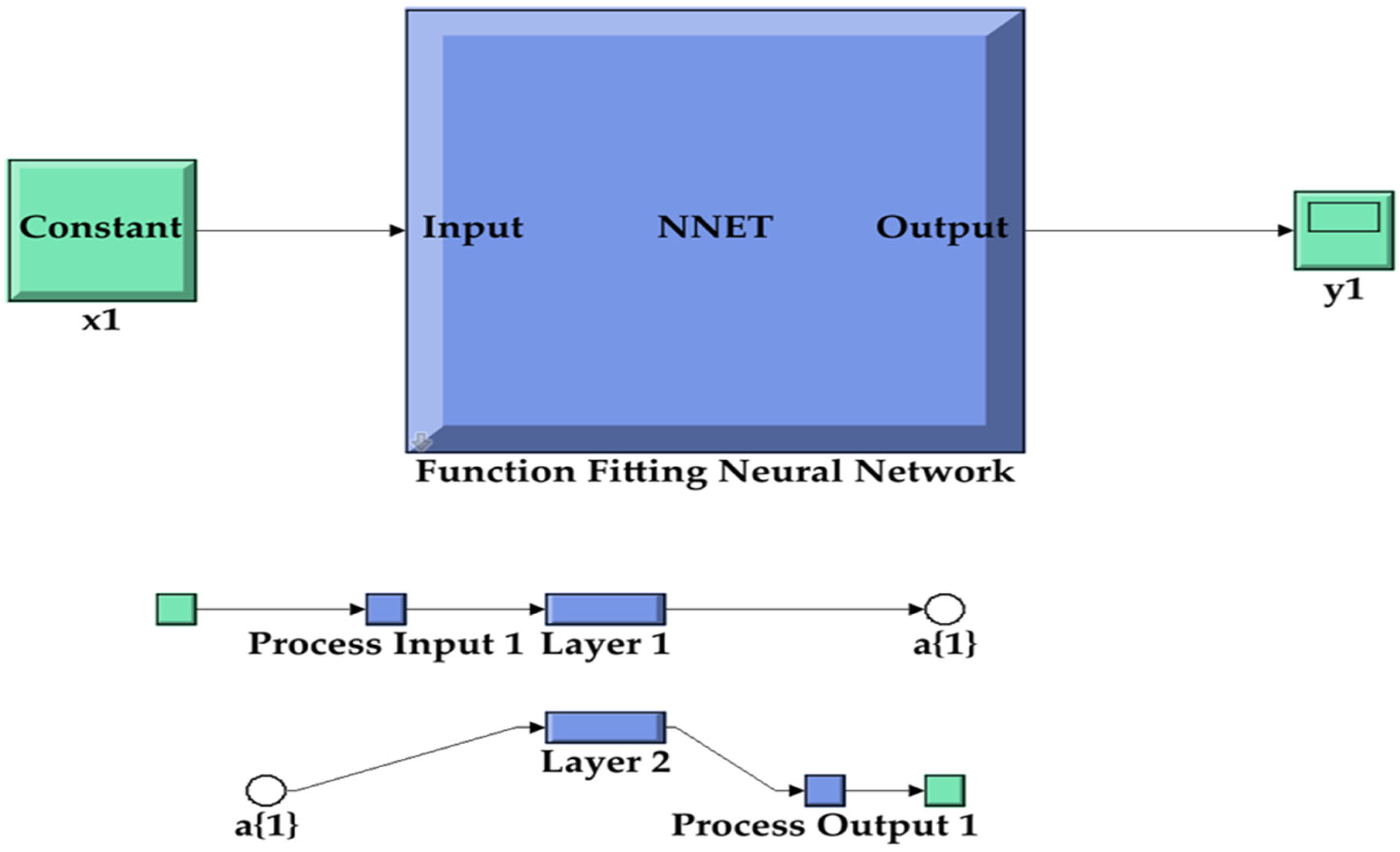
where V n e w is the updated voltage, V o l d   is the previous voltage value, and α is a positive step-size parameter that controls the algorithm’s convergence speed and stability. A larger value of α results in faster tracking but may increase sensitivity to noise, whereas a smaller value improves stability at the cost of slower convergence. Figure 5 and Figure 6 illustrate the architecture and performance of the NN-based MPPT controller. Figure 5 shows the training performance of the NN in terms of mean squared error (MSE) versus epochs. The MSE decreases as the number of epochs increases, indicating effective learning. A lower MSE confirms that the NN output closely matches the desired target. Hence, the trained network ensures accurate and efficient MPPT under varying environmental conditions. Figure 6 shows the NN block, which uses irradiance, temperature, and PV voltage as inputs to generate the optimal boost converter duty cycle.
Figure 5. Neural network performance.
Figure 6. NN block and layers inside block.
The MPPT controller indirectly affects the THD of a grid-connected photovoltaic system. An efficient MPPT controller maximises PV power extraction and maintains a stable DC-link voltage, which helps the inverter inject a cleaner sinusoidal current into the grid. The battery storage system, connected through a bidirectional DC–DC converter, absorbs excess power and supplies energy during power deficits, reducing DC-bus voltage fluctuations and enhancing system stability. As a result, the bidirectional converter smooths power variations, improves converter dynamics, and reduces current THD at the point of common coupling (PCC) [34].

2.5. Design of Predictive Power Flow Control (PPFC)

The integration of RES into modern power systems poses challenges related to intermittency, load uncertainty, and voltage regulation, as well as the need to ensure optimal battery operation and reduce power losses. The proposed framework uses an adaptive ANFIS-based PPFC system to forecast future power generation and load demand, thereby improving coordination among PV, BESS, and the grid [35]. This technique enables optimal power flow regulation while ensuring efficient switching of the Voltage Source Inverter (VSI). The mathematical modelling of the proposed PPFC controller is expressed below:
  • Step 1: Measurement and System State Acquisition: The control process begins with real-time acquisition of environmental and system variables. These inputs define the operating condition of the PV–battery system. This equation reflects the nonlinear and unpredictable nature of renewable energy generation.
The PV output power is governed by irradiance and temperature dependence [36]:
P P V =   η   ×   G   ×   ( 1     0.005   ×   ( T   25 ) )
  • where:
    •   P P V = photovoltaic power output;
    •   η = conversion efficiency of the PV module;
    • T = operating temperature (°C);
    •   G   = solar irradiance ( W / m 2 ).
  • Step 2: ANFIS-Based Nonlinear Prediction: The ANFIS model processes the measured inputs and predicts the system behaviour. Unlike conventional linear models, ANFIS captures nonlinear relationships and adapts to changing system conditions. The control signal is defined a
u ( k ) = f A N F I S ( G ,   T ,   P P V ,   S O C ,   P l o a d )
The expanded ANFIS equation for the proposed solar and battery integrated system is [37].
u ( k ) = Σ [ w i × ( a i · G + b i · T + c i · S O C + d i · P l o a d + e i ) ]
  • where:
    •   u ( k ) = control signal at time step k;
    •   w i = weight of rule I;
    •   a i , b i , c i , d i , e i = adaptive parameters.
  • Step 3: Battery Charging and Discharging Control: The battery acts as an energy storage device that compensates for a mismatch between PV generation and load demand. The ANFIS output determines the battery power:
P b a t = P c h P d i s
  • where:
    •   P b a t = net battery power;
    •   P c h = charging power;
    •   P d i s = discharging power.
State of charge (SoC) equation: This equation updates the battery energy level based on charging or discharging power [38].
S o C ( t ) = S o C ( t 1 ) + ( η b a t t × P b a t × Δ t ) C b a t
  • where
    •   S o C ( t ) = current battery state of charge;
    •   S o C ( t 1 ) = previous state of charge;
    •   Δ t = time interval.
Power Balance Equation: This equation ensures that total generated and stored power equals total demand and losses, maintaining system stability at every time step [39].
P P V + P d i s + P i m p o r t = P l o a d + P c h + P e x p o r t
  • where
    •   P i m p o r t = power drawn from conventional power generation;
    •   P e x p o r t = power delivered to the grid.
  • Step 4: Feedback and real-time learning: The system continuously compares predicted and actual values [40]:
Δ P = P p r e d i c t e d P a c t u a l
Parameters are updated as
θ n e w = θ o l d η × ( Δ P   θ )
  • where
    • θ = ANFIS parameters;
    • η = learning rate.
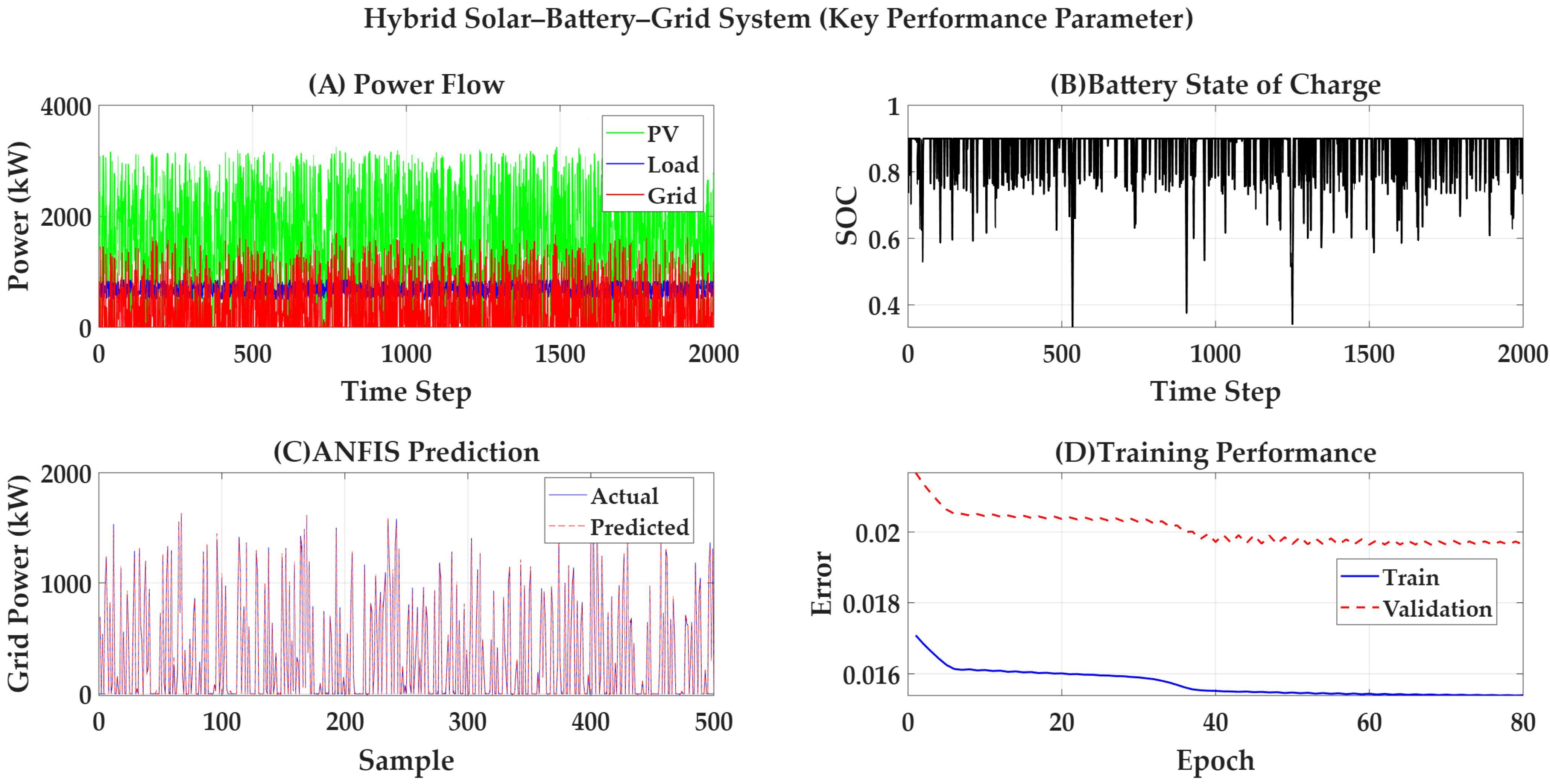
This adaptive control algorithm-based controller improves prediction accuracy, responds effectively to environmental variations, and maintains performance in real-time operation. Figure 7 demonstrates the power management of the proposed hybrid solar and battery-integrated grid system under varying irradiance and load conditions. The power flow results confirm reliable load satisfaction while minimising grid dependency through optimal battery utilisation. The state of charge (SoC) profile confirms stable charging–discharging behaviour within operational limits. Furthermore, the ANFIS model demonstrates high predictive accuracy, with strong agreement between actual and estimated grid power. The training convergence curve indicates efficient learning and model stability, supporting its suitability for real-time energy management applications.
Figure 7. The key performance results of the hybrid PV–battery–grid system showing (A) system power flow, (B) battery state of charge, (C) ANFIS prediction accuracy, and (D) training convergence behaviour.
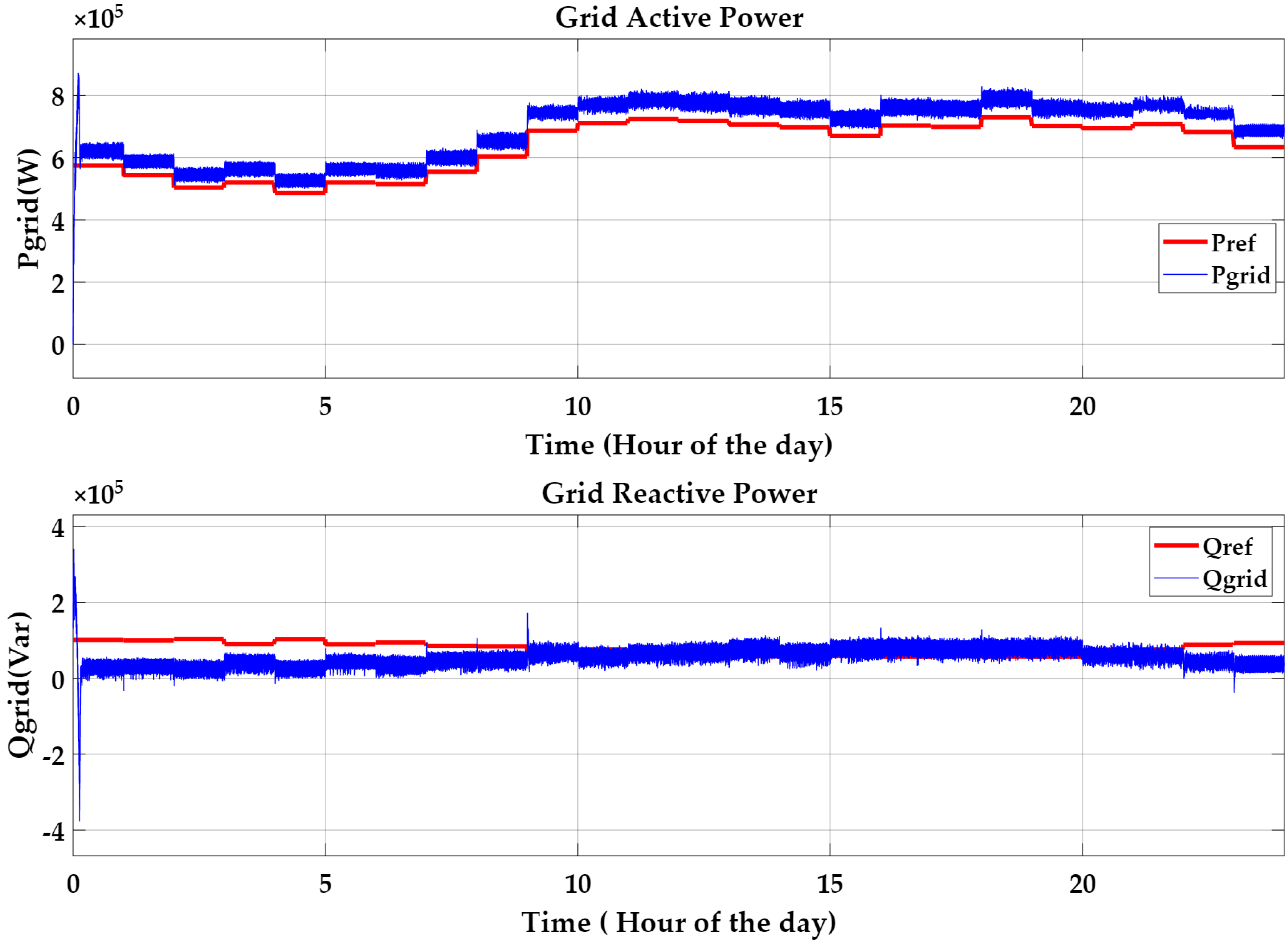
Figure 8 shows the performance of the proposed ANFIS-based PPFC controller system for a 24 h period. The upper graph shows the active power reference Pref and the actual grid active power Pgrid. The lower plot shows the reactive power reference, Qref, and the actual grid reactive power Qgrid. The results show that the average value of the grid power remains close to the predicted Pref throughout the operating time. The proposed PPFC helps to improve the prediction accuracy, battery management, and system stability, and reduces the grid dependency, making it suitable for renewable-integrated smart grid applications. The load data used in this study were obtained from the official Transpower New Zealand System Operator live dataset, available online at the Transpower live load data portal [41]. This dataset provides real-time electrical load information for different operational zones across New Zealand, including Auckland, measured in megawatts (MW).
Figure 8. Active and reactive power tracking of the PPFC power for a 24 h period.
For this study, the Auckland zone load profile was extracted from the live dataset and used to illustrate the variation in power demand over time, as shown in Figure 8. The recorded load values were appropriately scaled from megawatts (MW) to kilowatts (kW) to suit the analysis requirements. The resulting plot shows the temporal variation in electrical power demand in Auckland, highlighting typical load fluctuations throughout the observation period.

3. Simulation Results and Discussion

This study focuses on P&O, Inc, PSO, P&O–PSO, ANN, ANFIS, and fuzzy logic controllers. They are widely used and validated MPPT techniques for photovoltaic systems. These controllers represent conventional, optimsation-based, hybrid, and intelligent control methods [42]. For these reasons, a comprehensive comparison of efficiency, response speed and daily energy harvested under varying operating conditions will be conducted. Table 2 compares the efficiency of various MPPT techniques under varying environmental conditions. Conventional methods such as P&O and INC exhibit lower efficiency due to steady-state oscillations and slower tracking response. Optimisation-based techniques such as PSO and hybrid P&O–PSO improve efficiency but increase computational complexity. Intelligent methods such as FLC and ANN improve efficiency by better handling system nonlinearity. Among all the methods explored in this study, the ANFIS-based MPPT demonstrates the highest efficiency (up to 97.5%), due to its combined learning and reasoning capability.
Table 2. Comparison of MPPT controllers based on performance evaluation.
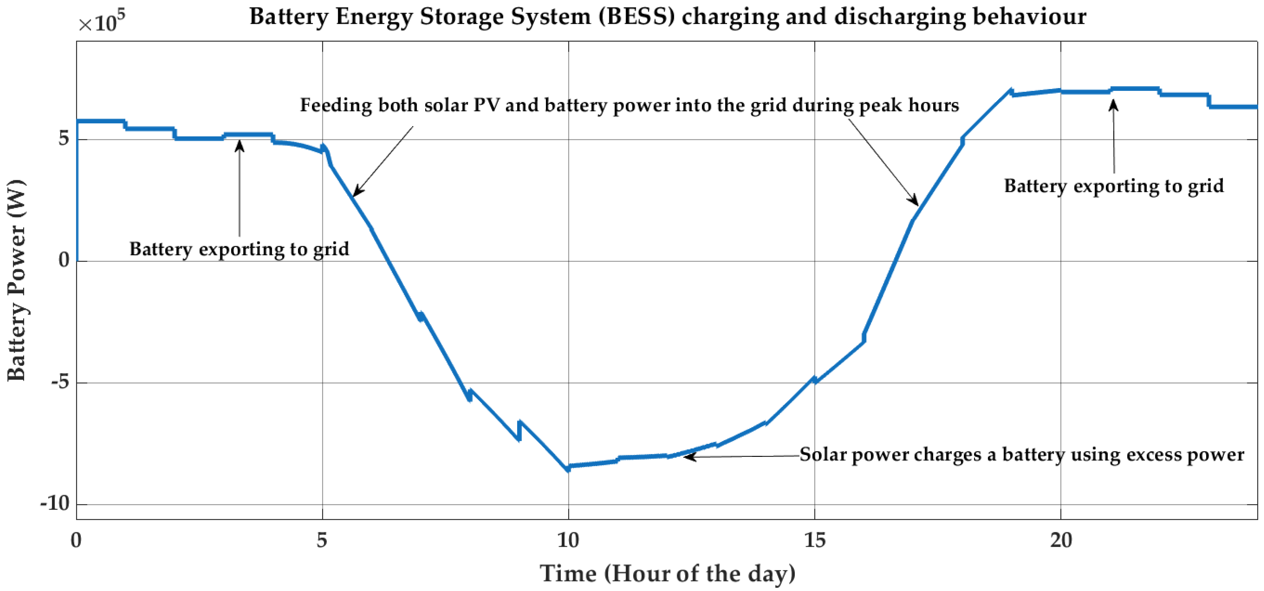
Figure 9 shows the hourly charging and discharging behaviour of the BESS over a 24 h period. The power value is positive, indicating the battery is discharging to meet grid demand during the morning and evening peak hours. Negative power values show the battery charging with excess solar PV generation in midday. This improves the utilisation of renewable energy, supports peak shaving, and increases overall grid reliability and stability.
Figure 9. The charging and discharging profile of the battery energy storage system (BESS).
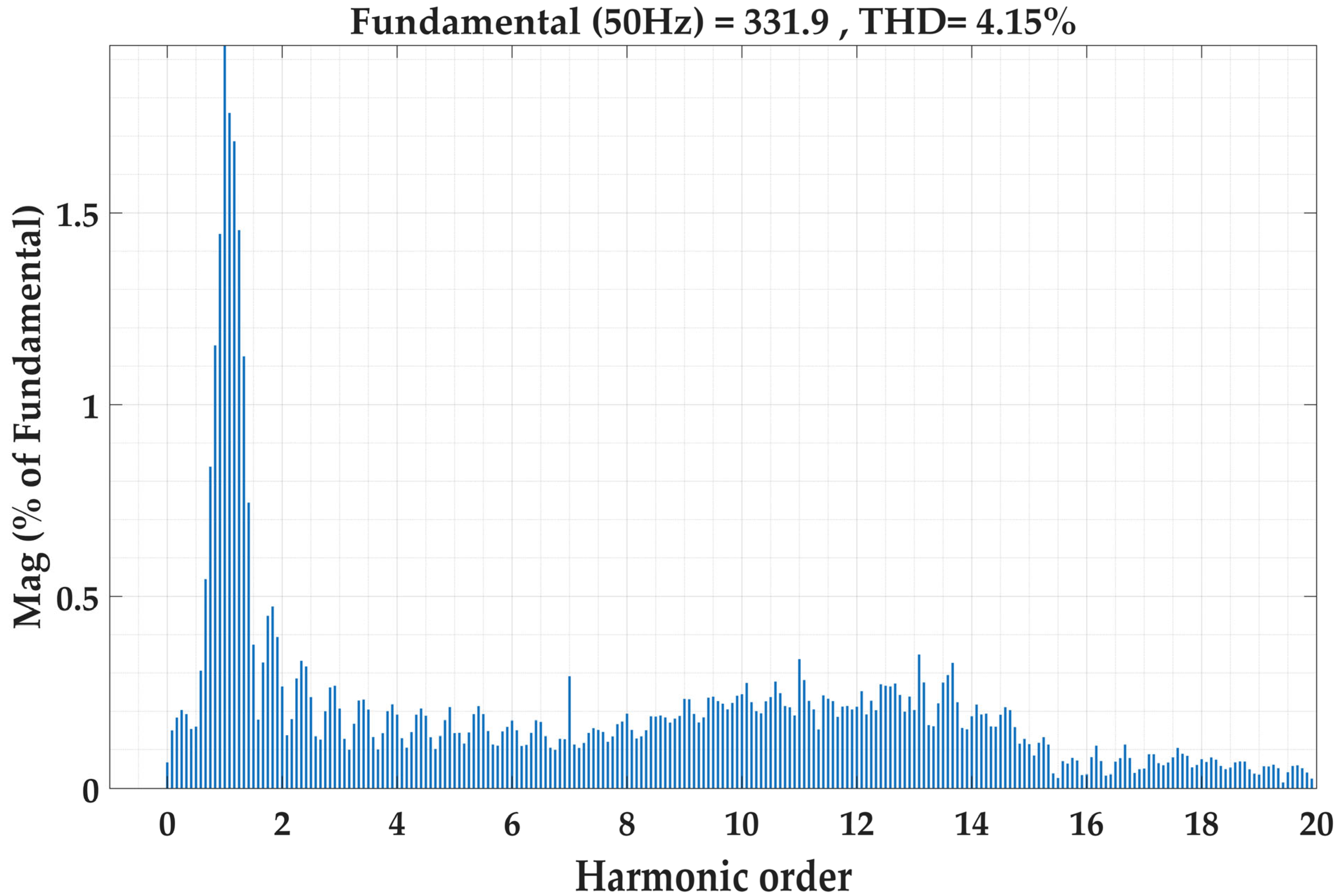
The total harmonic distortion (THD) was measured under the proposed power flow controller to evaluate the system’s power quality. The results, as shown in Figure 10, indicate that the THD values remain below the IEEE standard 519 [48] recommended limit of 5%. This confirms that the proposed controller effectively reduces harmonic distortion and maintains a stable output waveform. It helps to ensure improved power quality under different operating conditions.
Figure 10. FFT analysis of proposed PPFC-based power flow controller.

4. Future Work

This study presents a comparative analysis of MPPT techniques integrated with PPFC for harmonic mitigation in RES. The effectiveness of the proposed system was validated through hardware-in-the-loop (HIL) testing, which provided real-time verification of the controller’s performance and ensured practical feasibility under realistic operating conditions. Future research could explore the scalability of the proposed methods across diverse grid configurations and varying renewable energy sources. Specifically, investigating the performance of MPPT techniques under extreme environmental conditions and their adaptability to real-time data inputs could further improve system robustness. In addition, a comparative analysis of different DC–DC converters and inverter topologies can be conducted to evaluate their impacts on system efficiency, harmonic reduction, and overall performance. Future work also includes developing an HRES that integrates multiple sources, such as solar and wind, to optimise energy generation while minimising harmonic distortion.

5. Conclusions

This study presents a comprehensive evaluation of advanced MPPT techniques integrated with PPFC to mitigate harmonics in smart-grid systems effectively. The results demonstrate that the proposed control strategy successfully maintains the THD within the IEEE-recommended limit of 5%, thereby improving power quality and ensuring stable grid operation. A detailed comparative analysis confirmed that intelligent MPPT techniques, particularly the ANFIS-based approach, significantly improved the tracking efficiency, dynamic response, and system stability under nonlinear and varying environmental conditions. The integration of MPPT with PPFC further enhances overall performance by enabling coordinated control of power flow and harmonic suppression. The findings highlight the critical role of advanced and adaptive control strategies in improving the reliability and efficiency of renewable energy integration into modern power systems.

Author Contributions

S.V. managed the conceptualisation, methodology, investigation, and writing of the original draft. K.P. contributed to the methodology and investigation and reviewed and edited the manuscript. J.K. reviewed and edited the manuscript. Both K.P. and J.K. supervised the PhD student S.V. All authors have read and agreed to the published version of the manuscript.

Funding

This research received no external funding.

Data Availability Statement

The data is contained within the article.

Conflicts of Interest

The authors declare that they have no conflicts of interest.

References

  1. Ali, M.; Ahmad, M.; Koondhar, M.A.; Akram, M.S.; Verma, A.; Khan, B. Maximum power point tracking for grid-connected photovoltaic system using Adaptive Fuzzy Logic Controller. Comput. Electr. Eng. 2023, 110, 108879. [Google Scholar] [CrossRef] [Scilit]
  2. Electricity Authority Te Mana Hiko. NZ Wind and Solar Generation Scenarios; Electricity Authority Te Mana Hiko: Wellington, New Zealand, 2023.
  3. Fahad Al-Jame, J.B. AI-Driven Control Strategies for Power Converters in Solar–Wind Hybrid Energy Systems: Enhancing Efficiency, Reliability, and Grid Resilience. Trans. Power Electron. Renew. Energy Syst. 2025, 1, 1–7. [Google Scholar] [CrossRef] [Scilit]
  4. Benfatma, H.; Khouidmi, H.; Bessedik, B. Neural network and ACO algorithm-tuned PI controller for MPPT in a hybrid battery-supercapacitor energy storage system within DC micro-grid photovoltaic installations. J. Energy Storage 2025, 120, 116499. [Google Scholar] [CrossRef] [Scilit]
  5. Rajanala, P.; Kumar, M.K.; Giriprasad, A.; Choi, J.H.; Rao, K.V.G.; Sravan, V.S.; Reddy, C.R. Intelligent MPPT and coordinated control for voltage stability in brushless DFIG wind turbines. Sci. Rep. 2025, 15, 22669. [Google Scholar] [CrossRef] [Scilit] [PubMed]
  6. Wong, S.Y.; Li, J. Enhancing efficiency in photovoltaic hydrogen production: A comparative analysis of MPPT and electrolysis control strategies. MethodsX 2025, 14, 103220. [Google Scholar] [CrossRef] [Scilit] [PubMed]
  7. Guanghua, L.; Jamro, D.; Rahimoon, A.Q.; Memon, D.A.; Bhatti, Z.; Shah, S.H.H. Comparative analysis of GWO MPPT with conventional techniques in shaded PV arrays. Results Eng. 2025, 27, 106881. [Google Scholar] [CrossRef] [Scilit]
  8. Chegeni, M.; Askari, M.T.; Amirahmadi, M.; Ghods, V. Enhanced maximum power point tracking performance for PV systems in zero-energy buildings: An optimized SVR–TPE approach with hybrid energy storage and real-time capability. Unconv. Resour. 2026, 10, 100310. [Google Scholar] [CrossRef] [Scilit]
  9. Bouksaim, M.; Mekhfioui, M.; Srifi, M.N. A Comprehensive Decade-Long Review of Advanced MPPT Algorithms for Enhanced Photovoltaic Efficiency. Solar 2025, 5, 44. [Google Scholar] [CrossRef] [Scilit]
  10. Rekioua, D.; Mokrani, Z.; Kakouche, K.; Oubelaid, A.; Rekioua, T.; Alhazmi, M.; Ali, E.; Bajaj, M.; Dost Mohammadi, S.A.; Ghoneim, S.S.M. Coordinated power management strategy for reliable hybridization of multi-source systems using hybrid MPPT algorithms. Sci. Rep. 2024, 14, 10267. [Google Scholar] [CrossRef] [Scilit] [PubMed]
  11. Anselem Benet Raja, Y.; Thangaraj, A. Enhanced harmonic reduction and energy optimization in grid-connected photovoltaic-battery systems for improved power quality. J. Energy Storage 2026, 150, 120231. [Google Scholar] [CrossRef] [Scilit]
  12. Latreche, A.; Boukezzi, L.; Sellami, A. “Enhanced Power Management Strategy for Hybrid PV-Battery/Supercapacitor Systems in DC Microgrids using Advanced MPPT Control Techniques”. Electroteh. Electron. Autom. 2026, 74, 28–39. [Google Scholar] [CrossRef] [Scilit]
  13. Varun Sai, B.S.; Mohanty, R.; Mohanty, S.; Chatterjee, D.; Dhanamjayulu, C.; Chinthaginjala, R.; Kotb, H.; Elrashidi, A. An efficient MPPT techniques for inter-harmonic reduction in grid connected hybrid wind and solar energy systems. Heliyon 2024, 10, e27312. [Google Scholar] [CrossRef] [Scilit] [PubMed]
  14. Naima, B.; Belkacem, B.; Ahmed, T.; Benbouhenni, H.; Riyadh, B.; Samira, H.; Sarra, Z.; Elbarbary, Z.M.S.; Mohammed, S.A. Enhancing MPPT optimization with hybrid predictive control and adaptive P&O for better efficiency and power quality in PV systems. Sci. Rep. 2025, 15, 24559. [Google Scholar] [CrossRef] [Scilit] [PubMed]
  15. Bhaskar Reddy, K.V.; Murali, A.; P, A.R.; Laxma, P.; Siddhartha, D.S.; Bhargav, J.V. Analysis of a Grid-Connected Photovoltaic/Wind Hybrid Power System’s Performance. In Proceedings of the 2025 IEEE International Conference on Interdisciplinary Approaches in Technology and Management for Social Innovation (IATMSI), Gwalior, India, 6–8 March 2025; pp. 1–6. [Google Scholar]
  16. Kazem, H.A.; Chaichan, M.T.; Al-Waeli, A.H.A.; Gholami, A. A systematic review of solar photovoltaic energy systems design modelling, algorithms, and software. Energy Sources Part A Recovery Util. Environ. Eff. 2022, 44, 6709–6736. [Google Scholar] [CrossRef] [Scilit]
  17. Bhavani, T.; Rajababu, D.; Irfan, M.M.; Rakesh, T.; Sekhar, P.C.; Flah, A.; Kraiem, H. Design of a distributed power system using solar PV and micro turbine-based wind energy system with a flywheel energy storage. Sci. Rep. 2025, 16, 225. [Google Scholar] [CrossRef] [Scilit] [PubMed]
  18. Chaib, H.; Hassaine, S.; Mihoub, Y.; Moreau, S. Intelligent power control strategy based on self-tuning fuzzy MPPT for grid-connected hybrid system. Electr. Eng. Electromech. 2025, 3, 23–30. [Google Scholar] [CrossRef] [Scilit]
  19. Fahim, S.R.; Hasanien, H.M.; Turky, R.A.; Aleem, S.H.E.A.; Ćalasan, M. A Comprehensive Review of Photovoltaic Modules Models and Algorithms Used in Parameter Extraction. Energies 2022, 15, 8941. [Google Scholar] [CrossRef] [Scilit]
  20. Faiz, F.U.H.; Shakoor, R.; Raheem, A.; Umer, F.; Rasheed, N.; Farhan, M.; Umar, A. Modeling and Analysis of 3 MW Solar Photovoltaic Plant Using PVSyst at Islamia University of Bahawalpur, Pakistan. Int. J. Photoenergy 2021, 2021, 6673448. [Google Scholar] [CrossRef] [Scilit]
  21. Akeyo, O.M.; Rallabandi, V.; Jewell, N.; Ionel, D.M. The Design and Analysis of Large Solar PV Farm Configurations With DC-Connected Battery Systems. IEEE Trans. Ind. Appl. 2020, 56, 2903–2912. [Google Scholar] [CrossRef] [Scilit]
  22. Boutaghane, K.; Benbouhenni, H.; Bennecib, N.; Colak, I.; Elbarbary, Z.M.S.; Al-Gahtani, S.F. Using new control strategies to improve the effectiveness and efficiency of the hybrid power system based on the battery storage system. Sci. Rep. 2025, 15, 4730. [Google Scholar] [CrossRef] [Scilit] [PubMed]
  23. Jain, A.; Bhullar, S. Design and performance analysis of solar PV-battery energy storage system integration with three-phase grid. J. Power Sources 2025, 640, 236486. [Google Scholar] [CrossRef] [Scilit]
  24. Mazumdar, D.; Sain, C.; Biswas, P.K.; Sanjeevikumar, P.; Khan, B.; Iqbal, K. Overview of Solar Photovoltaic MPPT Methods: A State of the Art on Conventional and Artificial Intelligence Control Techniques. Int. Trans. Electr. Energy Syst. 2024, 2024, 8363342. [Google Scholar] [CrossRef] [Scilit]
  25. Sarvi, M.; Azadian, A. A comprehensive review and classified comparison of MPPT algorithms in PV systems. Energy Syst. 2021, 13, 281–320. [Google Scholar] [CrossRef] [Scilit]
  26. Ullah, K.; Awan, A.B.; Ishaq, M.; Soomar, A.M. MPPT Control Strategies for Grid-Connected Photovoltaic Systems: A Comparative Review Based on Key Parameters. Energies 2026, 19, 2866. [Google Scholar] [CrossRef] [Scilit]
  27. Elsafi, A.; Almohammedi, A.A.; Balfaqih, M.; Balfagih, Z.; Sabri, S. Comparative analysis of maximum power point tracking methods for power optimization in grid tied photovoltaic solar systems. Discov. Appl. Sci. 2025, 7, 976. [Google Scholar] [CrossRef] [Scilit]
  28. Loganathan, V.; Jothi Swaroopan, N.M. MPPT of solar PV systems using PSO memetic algorithm considering the effect of change in tilt angle. Sci. Rep. 2025, 15, 7818. [Google Scholar] [CrossRef] [Scilit] [PubMed]
  29. Dwaza, K.N.; Krishnamurthy, S.; Mataifa, H. Time-Domain Modeling and Simulation of Hybrid Perturb and Observe–Particle Swarm Optimization Maximum Power Point Tracking for Enhanced CubeSat Photovoltaic Energy Harvesting. Energies 2025, 18, 5957. [Google Scholar] [CrossRef] [Scilit]
  30. National Aeronautics and Space Administration (NASA). The Data Was Obtained from National Aeronautics and Space Administration (NASA) Langley Research Center’s Prediction of Worldwide Energy Resources (POWER) Project Funded Through the NASA Earth Science Division; National Aeronautics and Space Administration (NASA): Washington, DC, USA, 2025.
  31. Moyo, R.T.; Tabakov, P.Y.; Moyo, S. Design and Modeling of the ANFIS-Based MPPT Controller for a Solar Photovoltaic System. J. Sol. Energy Eng. 2021, 143, 041002. [Google Scholar] [CrossRef] [Scilit]
  32. Yilmaz, U.; Kircay, A.; Borekci, S. PV system fuzzy logic MPPT method and PI control as a charge controller. Renew. Sustain. Energy Rev. 2018, 81, 994–1001. [Google Scholar] [CrossRef] [Scilit]
  33. Zečević, Ž.; Rolevski, M. Neural Network Approach to MPPT Control and Irradiance Estimation. Appl. Sci. 2020, 10, 5051. [Google Scholar] [CrossRef] [Scilit]
  34. Echab, O.; Ech-Cherki, N.; Nassar-Eddine, I.; Chetouani, E.; Obbadi, A.; Errami, Y.; Sahnoun, S.; Aoutoul, M. Improved MPPT algorithm for grid-connected PV system. In Proceedings of the 2025 5th International Conference on Innovative Research in Applied Science, Engineering and Technology (IRASET), Fez, Morocco, 15–16 May 2025; pp. 1–5. [Google Scholar]
  35. Meng, Q.; He, Y.; Hussain, S.; Lu, J.; Guerrero, J.M. Robust single-layer predictive control for grid-tied solar systems with integrated maximum power point tracking and power flow optimization. Energy Rep. 2025, 14, 2557–2569. [Google Scholar] [CrossRef] [Scilit]
  36. Razmara, M.; Bharati, G.R.; Hanover, D.; Shahbakhti, M.; Paudyal, S.; Robinett, R.D. Building-to-grid predictive power flow control for demand response and demand flexibility programs. Appl. Energy 2017, 203, 128–141. [Google Scholar] [CrossRef] [Scilit]
  37. Babiker, A.; Ahmad, S.S.; Ahmed, I.; Khalid, M.; Abido, M.A.; Saleh Al-Ismail, F. Optimal Power Flow: A Review of State-of-the-Art Techniques and Future Perspectives. IEEE Access 2025, 13, 60012–60039. [Google Scholar] [CrossRef] [Scilit]
  38. Kumar, V.; Sharma, S.; Kumar, V.; Sharma, S.; Dev, A. Optimal voltage and frequency control strategy for renewable-dominated deregulated power network. Sci. Rep. 2025, 15, 398. [Google Scholar] [CrossRef] [Scilit] [PubMed]
  39. Biswas, P.; Rashid, A.; Masum, A.A.; Nasim, M.A.A.; Anas Ferdous, A.S.M.; Gupta, K.D.; Biswas, A. An Extensive and Methodical Review of Smart Grids for Sustainable Energy Management- Addressing Challenges with AI, Renewable Energy Integration, and Leading-Edge Technologies. IEEE Access 2026, 14, 44798–44815. [Google Scholar] [CrossRef] [Scilit]
  40. Tang, H.; Li, B.; Zhang, Y.; Pan, J.; Wang, S. A coordinated predictive scheduling and real-time adaptive control for integrated building energy systems with hybrid storage and rooftop PV. Renew. Energy 2025, 239, 122047. [Google Scholar] [CrossRef] [Scilit]
  41. Transpower. Live Load Data. 2026. Available online: https://www.transpower.co.nz/system-operator/live-system-and-market-data/live-load-data (accessed on 10 May 2026).
  42. Chandola, J.; Pundir, S.; Sharma, A.; Song, Y.; Fekete, G.; Singh, T. Recent advances in MPPT techniques for photovoltaic systems: A review of classical (P&O, IC), intelligent (ANN), optimization (PSO) and hybrid (ANN-PSO) methods. Results Eng. 2026, 29, 109395. [Google Scholar] [CrossRef] [Scilit]
  43. Aldulaimi, M.Y.M.; Çevik, M. AI-Enhanced MPPT Control for Grid-Connected Photovoltaic Systems Using ANFIS-PSO Optimization. Electronics 2025, 14, 2649. [Google Scholar] [CrossRef] [Scilit]
  44. Zhang, X.; Zhao, B.; Cui, H.; Zhao, G.; Li, Y.; Huangfu, Y. A hybrid global maximum power point tracking control method based on particle swarm optimization (PSO) and perturbation and observation (P&O). Electr. Power Syst. Res. 2025, 248, 111967. [Google Scholar] [CrossRef] [Scilit]
  45. Melhaoui, M.; Rhiat, M.; Oukili, M.; Atmane, I.; Hirech, K.; Bossoufi, B.; Almalki, M.M.; Alghamdi, T.A.H.; Alenezi, M. Hybrid fuzzy logic approach for enhanced MPPT control in PV systems. Sci. Rep. 2025, 15, 19235. [Google Scholar] [CrossRef] [Scilit] [PubMed]
  46. Et-Torabi, K.; Mesbahi, A.; Nouaiti, A. Experimental Validation of Intelligent MPPT Control for Photovoltaic Energy Chain. Eng. Technol. Appl. Sci. Res. 2025, 15, 21754–21761. [Google Scholar] [CrossRef] [Scilit]
  47. Türkay, Y.; Yüksek, A.G. Investigating the Potential of an ANFIS-Based Maximum Power Point Tracking Controller for Solar Photovoltaic Systems. IEEE Access 2025, 13, 41768–41784. [Google Scholar] [CrossRef] [Scilit]
  48. IEEE Std 519-2014; 2014 Revised as IEEE Std 519-2022. IEEE Standard for Harmonic Control in Electric Power Systems; IEEE: New York, NY, USA, 2022.
Disclaimer/Publisher’s Note: The statements, opinions and data contained in all publications are solely those of the individual author(s) and contributor(s) and not of MDPI and/or the editor(s). MDPI and/or the editor(s) disclaim responsibility for any injury to people or property resulting from any ideas, methods, instructions or products referred to in the content.

Article Metrics

Citations

Article Access Statistics

Multiple requests from the same IP address are counted as one view.