Article

Cell-Level Modeling Approach for Accurate Irradiance Estimation in Bifacial Photovoltaic Modules


by
Monica De Riso
,
Gerardo Saggese
,
Pierluigi Guerriero
,
Santolo Daliento
and
Vincenzo d’Alessandro
*
Department of Electrical Engineering and Information Technology, University of Naples Federico II, via Claudio 21, 80125 Naples, Italy
*
Author to whom correspondence should be addressed.
Solar 2026, 6(2), 15; https://doi.org/10.3390/solar6020015
Submission received: 19 December 2025 / Revised: 26 February 2026 / Accepted: 6 March 2026 / Published: 11 March 2026
(This article belongs to the Special Issue Efficient and Reliable Solar Photovoltaic Systems: 2nd Edition)

Abstract

Accurate prediction of the energy yield of bifacial photovoltaic (PV) modules requires a proper evaluation of albedo irradiance and the associated mismatch losses. In this work, an advanced tool for the assessment of the power production of bifacial modules is presented. The tool benefits from a refined numerical evaluation of ground-reflected irradiance performed through a view-factor-based cell-level approach within a realistic three-dimensional (3D) Sun-module-shadow geometry. This allows capturing both vertical and lateral nonuniformities in the irradiance distributions over the module surfaces, which are neglected in conventional module-level models. The irradiances incident on the cells are subsequently supplied to a circuit-based block, operating with a cell-level granularity as well, which computes the IV characteristics and the maximum power point (MPP) at selected time instants. Simulations performed on a simplified tool variant assuming uniform albedo irradiance show that this approximation leads to a non-negligible overestimation of power output. An extensive comparison against state-of-the-art tools, including the previous version of our framework, allows us to conclude that the proposed method is especially advantageous for standalone modules or short-row configurations under medium-to-high albedo conditions. Moreover—like its previous version—the tool can handle a large variety of detrimental effects, namely, partial architectural shading, localized snow coverage, bird droppings, and faulty cells. Additionally, a non-zero elevation from the ground can be effectively described. It is also found that south-oriented 30°-tilted bifacial modules suffer from appreciable albedo-induced mismatch losses on the rear surface during summer under medium-albedo conditions, whereas vertically-mounted West- and East-oriented configurations are less affected by such losses. Experimental validation confirms the accuracy of the proposed framework.

1. Introduction

Significant advancements in traditional photovoltaic (PV) technologies based on monocrystalline and polycrystalline silicon have been driven by the constant growth of the global demand for renewable energy. PV systems have profited exponentially in recent years from sophisticated modeling, diagnostic, and protection methods designed to increase energy production and reliability under actual operating situations. Examples include creative hot-spot mitigation techniques [1] and the use of on-field impedance spectroscopy for health assessment [2]. Building upon these consolidated developments in standard PV modules, research attention has progressively shifted toward bifacial PV modules emerging as a promising solution due to their ability to capture light from both the front and rear surfaces [3,4,5,6,7,8,9,10]. By harnessing reflected and diffused sunlight on the rear side, bifacial modules can produce more energy per unit area compared to the conventional monofacial counterparts, gaining up to 31% when installed in areas with high albedo surfaces (i.e., snow and white rooftops) [11]. Nevertheless, accurately assessing their performance and energy production can be challenging due to the influence of the surrounding environment on light absorption. A key issue for bifacial technology is the accurate estimation of the irradiance impinging on the rear side under different operating scenarios [12]. The literature proposes several studies to predict the amount of sunlight reaching the rear side of bifacial PV modules, based on different approaches such as ray tracing [13,14,15,16,17,18,19,20] and view factor [11,21,22,23,24,25,26,27,28,29].
Ray tracing simulates the path of light rays and their interaction with objects in a scene surrounding the bifacial PV module. The main advantage of this approach is the ability to account for nonuniform light reflection, varying albedo, and nearby objects that can cause partial shading on the module under investigation, enabling an accurate irradiance estimation at the cell level. However, ray tracing suffers from a high computational burden, and simulations can take a long time to complete [3,30,31]. View-factor-based methods are often preferable when the target is to obtain fast, robust, and physically consistent estimates of irradiance for relatively simple geometries and/or large PV installations. Such methods have been employed to quantify the performance of bifacial modules over the monofacial counterparts [21,24,27], as well as to explore the effects of various geometric and weather parameters on the power production [25,28]. In existing view-factor-based models, the solar irradiances hitting the front and rear of the bifacial PV module are assumed to be uniform because they are computed at the module level. However, in real-world conditions, light nonuniformity might affect both the front and rear, thus leading to mismatch losses [14]; for instance, the rear surface can suffer from a nonuniformity in the albedo reflection. Such mismatch-related phenomena are known to affect not only module performance but also power-conversion stages, where deep nonuniform operating conditions may compromise control stability in advanced inverter architectures [32], while similar nonuniform patterns can trigger significant reliability concerns in conventional PV modules, further highlighting the importance of accurate cell-level assessment.
In our previous paper [27], a tool was proposed for the evaluation of the power production of bifacial modules. The framework includes a code that analytically computes a spatially-uniform irradiance value on the front side and another value on the rear side (module-level approach) according to the view-factor-based modeling strategy presented in [26]. Then, the front and rear irradiances are provided to a cell-level Spice block for the circuit-based simulation of the I– V characteristic at a chosen clock time. The cell-level nature of the Spice unit allows for the individual modification of the irradiances (and thus the PV currents), as well as of other key parameters, of selected cells prior to circuit simulation in order to account for localized architectural shading (due to chimneys, antennas, fences, other buildings), snow, bird droppings, malfunctioning cells, etc. The analytical model for the rear-side irradiance component dictated by diffuse ground albedo reflection in [26] was conceived to fix a significant theoretical flaw of former approaches (e.g., [22]) by including the dependence of the sky dome portion seen from the self-shaded ground. However, such an albedo irradiance model still suffers from other limitations common to all previous view-factor-based approaches, i.e., (i) the evaluation relies on a simplified 2D Sun-module-shadow scenario where the Sun is always seen by the module front, and (ii) the albedo reflection is assumed to be uniform, that is, it is commonly shared by the rear sides of all cells.
In this paper, we present an advanced version of the tool in [27], where the view-factor-based computation of the albedo irradiance is numerically performed within a realistic 3D Sun-module-shadow scenario with a cell-level granularity, whereas the analytical model for the evaluation of beam (direct) irradiance and diffuse irradiance from the sky, as well as the cell-level Spice block for I– V simulation, are kept unchanged. By virtue of the novelty in the irradiance model, (i) the albedo reflection is more accurately evaluated, and (ii) both vertical and lateral irradiance nonuniformities are explicitly captured; as a result, the framework enables a rigorous assessment of the impact on the power production of potential albedo-induced mismatch losses through the cell-level Spice block.
The remainder of this work is organized as follows. In Section 2, an overview of the proposed approach for irradiance evaluation, as well as of the circuit-based block, is provided. Section 3 presents detailed comparative analyses between the proposed tool and (i) a traditional module-level approach; (ii) the previous tool variant [27] and the widely used open-source pvlib library [29]. Section 4 demonstrates the capability of the tool to quantify the influence of the elevation of the bifacial module above ground. In Section 5, a simulation campaign is performed to estimate the mismatch loss in various PV installations. In Section 6, the tool is experimentally validated. Conclusions are finally drawn in Section 7.

2. Proposed Approach

In the following, for the sake of simplicity we focus on a standalone bifacial PV module comprising N cells, although our approach can handle the case of strings or arrays composed by M modules.
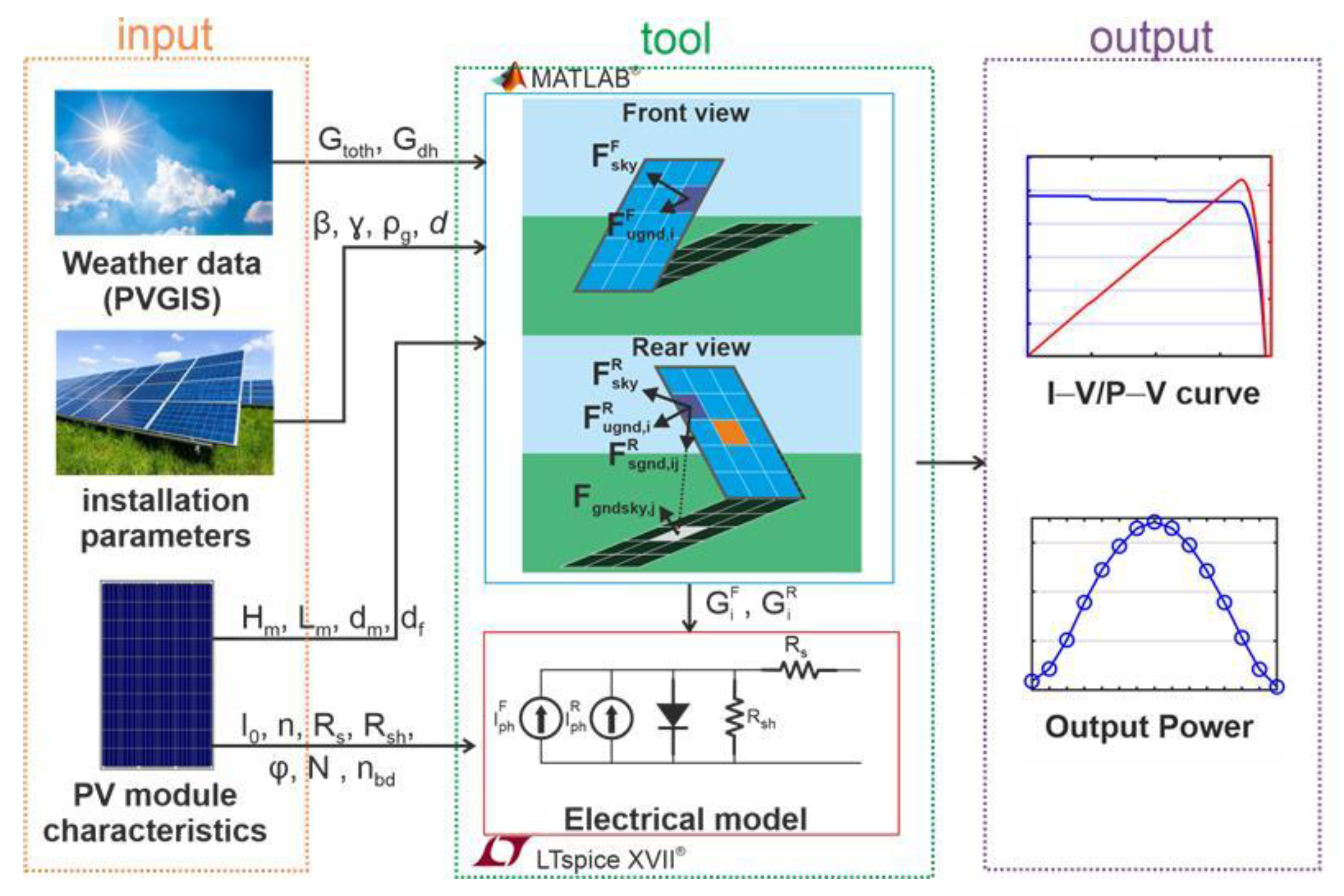
The complete workflow of our tool is sketched in Figure 1, and can be subdivided into (i) a code for the evaluation of the irradiances hitting the front and rear sides of the cells and (ii) a circuit-based block for the simulation of the I– V characteristics and produced power at chosen time instants during the selected day.

2.1. Irradiance Model

The input of the proposed irradiance model includes the following data:
  • The geographic location (latitude and longitude) where the module is installed.
  • The total irradiance G t o t h and diffuse irradiance G d h on the horizontal plane, which can be retrieved from the PhotoVoltaic Geographical Information System (PVGIS) database [33] for an average day of the month; in [33], it is stated that the aforementioned irradiances were evaluated at chosen clock times from satellite data “through a sophisticated algorithm accounting for sky obstruction (shading) by local terrain features (hills or mountains) calculated from a digital elevation model”. The horizontal beam irradiance G b h is simply determined as G t o t h G d h .
  • The installation parameters, namely, tilt angle β, module azimuth γ, and elevation from ground level (also denoted as ground clearance) d.
  • The ground albedo ρ g . Let us recall that accepted ρ g values are typically <0.1 for fresh asphalt, 0.1–0.2 for bare soil, cultivated ground, and weathered concrete, 0.25–0.3 for green grass or vegetation, 0.4 for desert sand, 0.5–0.55 for light-colored concrete, gravel or crushed stone, and 0.8–0.85 for highly-reflective surfaces such as white-painted/-coated surfaces and freshly fallen snow.
  • The geometrical dimensions of the module, namely, height H m , length L m , thickness d m , and width of the metal frame d f .
A three-dimensional (3D) scenario of the PV installation is created in Matlab R2024b for the calculation of the beam, sky-diffuse, and albedo-reflected irradiance components. As mentioned earlier, similar to [27], the front sides of the cells collect identical values of beam (direct) irradiance and irradiance diffuse from the sky, and the same applies to the rear sides, with these components being calculated through conventional, well-accepted, analytical formulations. Conversely, a numerical cell-level strategy is introduced to determine the albedo-induced irradiances on the front and rear sides. Owing to this combined analytical–numerical nature, the overall irradiance model will hereafter be denoted as semi-analytical.
The global irradiance hitting the front side of the i-th cell G i F is computed using the transposition model [34], i.e.,
G i F = G b F + G d F + G a , i F
where G b F is the beam irradiance (common to all cell front sides), G d F is the diffuse irradiance from the sky (common to all cell front sides), and G a , i F is the irradiance due to the albedo reflection from the ground (independently determined for the front side of each cell). These contributions are evaluated as
G b F = G b h R b F G d F = G d h F s k y F G a , i F = G t o t h ρ g F u g n d , i F + G d h ρ g j = 1 N F s g n d , i j F F g n d s k y , j
R b F is the ratio of tilted irradiance to horizontal irradiance, given by
R b F = { cos θ sin α γ π / 2 ω γ + π / 2 0 ω < γ π / 2 or ω > γ + π / 2 }
where θ is the incidence angle of the solar rays on the front side, α is the solar altitude, and ω is the hour angle [27].
  • F s k y F is the view factor from a cell front to the sky (the same for all cells); for a uniformly cloudy sky (isotropic conditions), it is given by
    F s k y F = 1 + cos β 2 = cos 2 β 2
  • If the sky is clean or partially cloudy (anisotropic conditions), either the formulation in [35] or the one in [36] can be activated for F s k y F to account for mechanisms related to the position of the Sun in the sky, namely, horizon brightening and circumsolar radiation.
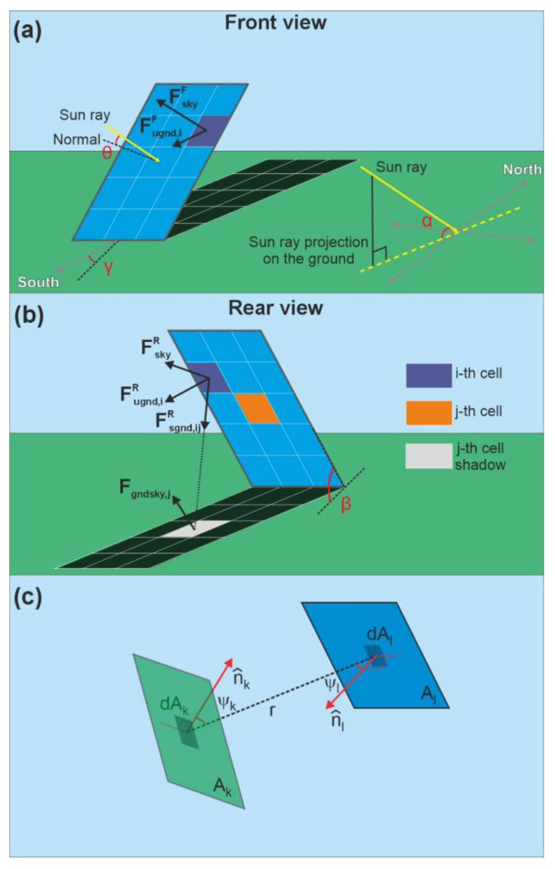
  • The albedo diffuse irradiance G a , i F is obtained by summing two contributions, namely, the reflection from the unshaded ground (ugnd) and the reflection from the ground shaded by the module (sgnd). As mentioned earlier, this evaluation is carried out with a view-factor-based cell-level approach, in which the module is discretized into N cells, as shown in Figure 2; F u g n d , i F is the view factor of the i-th cell front to unshaded ground, F s g n d , i j F is the view factor of the i-th cell front to the shadow cast by the j-th cell (0 for the specific case represented in Figure 2, where the solar rays hit the front side of the module), and F g n d s k y , j is the view factor of the shadow cast by the j-th cell to the sky (also 0 in Figure 2).
In a similar fashion, the global irradiance hitting the rear side of the i-th cell G i R is obtained as
G i R = G b R + G d R + G a , i R
where G b R is the beam irradiance (shared by all cell rear sides), G d R is the sky-diffuse irradiance (common to all cell rear sides), and G a , i R is the irradiance due to the albedo reflection from the ground (independently computed for the rear side of each cell). These irradiances are evaluated as
G b R = G b h R b R G d R = G d h F s k y R G a , i R = G t o t h ρ g F u g n d , i R + G d h ρ g j = 1 N F s g n d , i j R F g n d s k y , j
The ratio R b R of tilted irradiance to horizontal irradiance is determined as
R b R = 0 γ π / 2 ω γ + π / 2 cos θ sin α ω < γ π / 2 or ω > γ + π / 2
obtained from (3) replacing θ with 180 ° θ .
  • Under isotropic conditions, F s k y R is given by
    F s k y R = 1 cos β 2 = sin 2 β 2
    obtained from (4) replacing β with 180 ° β . Under anisotropic conditions, again it is possible to enable one of the formulations introduced in [35,36] by substituting β with 180 ° β and θ with 180 ° θ .
  • The albedo diffuse irradiance G a , i R is obtained by adding the reflection from the unshaded ground and the one from the ground shaded by the module. With reference to Figure 2, F u g n d , i R is the view factor of the i-th cell rear to unshaded ground, F s g n d , i j R is the view factor of the i-th cell rear to the shadow cast by the j-th cell on the ground, and F g n d s k y , j is the view factor of the portion of the ground shaded by the j-th cell to the sky. It is worth noting that, within traditional view-factor-based module-level modeling methods, the view factor between the module-generated shadow and the sky dome was first introduced in [26] (and then used in [27]), whereas earlier approaches had improperly neglected it.
View factors F u g n d , i F , F s g n d , i j F , F g n d s k y , j , F u g n d , i R , and F s g n d , i j R are determined with the following general strategy. With reference to Figure 2c, the view factor F k l between the surfaces A k and A l is defined as the fraction of the radiant energy leaving A k that directly reaches A l . Under the assumptions of diffuse (Lambertian) emission/reflection and unitary visibility factor, the differential view factor between two elemental areas d A k and d A j separated by a distance r is given by
d F k l = cos ψ k cos ψ l π r 2 d A k d A j
where ψ k and ψ l are the angles between the line connecting the two elements and their respective outward normals. The view factor F k l is then obtained by integrating the above expression over both surfaces and normalizing by the emitting area A k :
F k l = 1 A k A k A l cos ψ k cos ψ l π r 2 d A k d A j
We numerically evaluate (10) using the adaptive quadrature algorithm.
This semi-analytical modeling approach enables an accurate representation of vertical nonuniformity in albedo irradiance. For instance, cells located closer to the shaded ground receive lower albedo irradiance than those positioned higher, as they suffer from a poor view of the unshaded ground. Furthermore, the method captures potential lateral nonuniformity. As an example, in a standalone PV module, edge cells typically experience different albedo irradiance compared to inner cells (edge effect). Similarly, within a PV array, cells belonging to modules located at the array extremities receive albedo irradiance levels that differ from those of centrally-positioned modules.
In the irradiance modeling procedure, it is also possible to enable the presence of a d f -wide metal frame on the rear, described as an opaque, non-reflective surface, which reduces the view factors of the rear sides of some cells to the sky dome and ground, and is assumed not to cause self-shading. To account for such an effect, reduction factors are introduced in the evaluation of F s k y R , F u g n d , i R , and F s g n d , i j R .

2.2. Computational Burden

As previously mentioned, the new version of the tool differs from the earlier one [27] only in the evaluation of the albedo-induced irradiance, which is now performed at the cell level using a numerical approach based on (10). It is evident that the new methodology leads to an improvement in terms of accuracy; however, it is equally clear that the associated complexity—and thus the computational burden—increases compared to the fully analytical approach introduced in [26] and adopted in [27]. Therefore, this point requires further discussion.
Although the analysis in Section 3 is performed for a standalone module, both the presented tool and the earlier version [27] can be employed for an array of M modules, each comprising N cells.
In both tools, the irradiance is evaluated with unoptimized Matlab codes. For a given time instant, the code in [27] determines only one total irradiance landing to all the front sides of the cells, and only one total irradiance incident on all the rear sides of the cells with a computationally-cheap fully analytical approach. Conversely, the code in the proposed framework, besides analytically computing the beam and sky-diffuse irradiances as in [27], numerically evaluates F u g n d , i F , F g n d s k y , j , F u g n d , i R for each of the N M cells embedded in the array, as well as the N M 2 factors F s g n d , i j F and the N M 2 factors F s g n d , i j R , such a computation being the most onerous in the whole irradiance estimation procedure. As a consequence, the asymptotic complexity is upper bounded by O N M 2 . However, it is important to clarify that in practical applications geometric periodicity can be exploited: modules located away from the array boundaries experience nearly identical irradiance distribution, allowing view factors to be computed once for representative modules and reused across equivalent positions.
For the case of the standalone module N = 108 , M = 1 considered as a case study in the following sections, the CPU time for the whole cell-level irradiance evaluation on the front and rear surfaces amounted to about 1 min on a standard PC.

2.3. Circuit-Based Block

The circuit-based cell-level block is intended to evaluate the I– V characteristic of the module (and consequently the maximum produced power, or MPP) at each clock time during the day. This unit is basically unchanged with respect to the one included in [27], and can be described as follows. Each of the N cells of the module is represented by the single diode model (SDM). The module is subdivided into submodules, each equipped with a bypass diode. The mathematical model for the i-th cell is
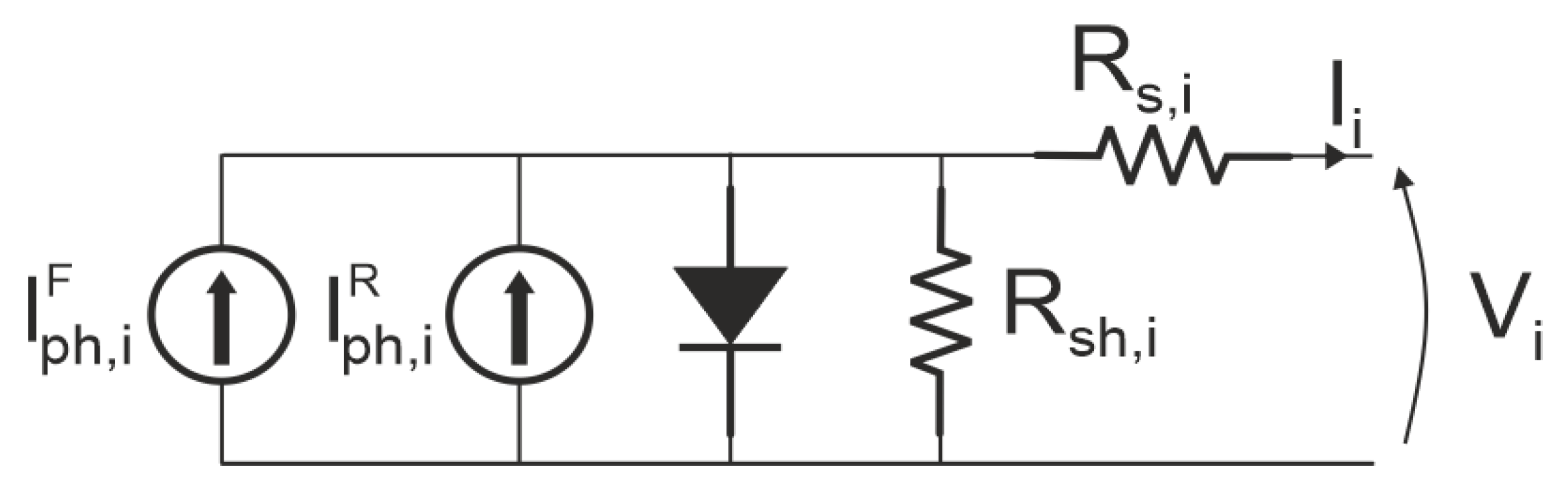
I i = I p h , i F + I p h , i R I 0 exp V i + R s , i I i n V T 1 V i + R s , i I i R s h , i
where V i and I i are the voltage across the cell and the current flowing through it, respectively, V T is the thermal voltage, I 0 and n are the reverse saturation current and ideality factor that can be extracted from the datasheet of the module, R s , i and R s h , i are the series and shunt resistances, I p h , i F and I p h , i R are the components of the photogenerated current associated with the front and rear irradiances G i F and G i R according to
I p h , i F = G i F G S T C I s c , S T C I p h , i R = G i R φ G S T C I s c , S T C
where I s c , S T C is the short-circuit current measured by keeping the front side under standard test conditions (STCs), namely, irradiance G S T C = 1000 W / m 2 , 1.5 AM, and cell temperature equal to 25 °C, and covering the rear side or at least markedly limiting its irradiance; φ is the bifaciality factor, i.e., an efficiency reduction factor needed to account for the fact that the PV cell is asymmetric, being technologically designed to maximize light absorption on the front surface.
The SDM is implemented in the form of a subcircuit making use of two parallel current sources for I p h , i F and I p h , i R in the environment of LTspice XVII [37], as depicted in Figure 3. The macrocircuit modeling the entire module is described as a netlist.
As mentioned earlier, similar to [27], it is possible to modify the irradiances, as well as other parameters, for selected cells prior to circuit simulation in order to describe localized architectural shading, bird droppings, cracked cells, etc.
The proposed tool is in principle suited (i) to evaluate the cell temperature from the irradiances hitting front and rear and (ii) to account for the temperature dependence of the PV currents and of the intrinsic diode behavior, as done in the former version [27] and in another fully electrothermal tool variant devised for monofacial modules [38]. However, when conducting the comparative analyses in Section 3, (i) and (ii) are deactivated (that is, the temperature of the cells is inherently assumed to be 25 °C) to allow an easier interpretation of results. For the same reason, the effect of light reflection on the module surfaces, also known as the incidence angle modifier (IAM), was not accounted for in Section 3, although the IAM functions presented in [39,40] can be enabled.

3. Comparison with Other Approaches

To assess the performance and accuracy of the proposed tool relying on a cell-level strategy for the assessment of the albedo reflection, we present a detailed comparative simulation analysis against other approaches. The comparison is performed on the Suntech STP430S-C54 bifacial module in half-cut technology [41], whose main specifications are reported in Table 1. Such a module is assumed to be located in Naples (Italy), in the absence of partial shading and malfunctioning cells.

3.1. Comparison with a Traditional Module-Level Approach

The first comparison was made with a module-level approach. Such an approach follows the same framework as the proposed tool, except for the calculation of the albedo-induced irradiance; in particular, the same realistic 3D Sun-module-shadow scenario used in the proposed model was adopted, but the module front and rear sides were represented as single, unified surfaces, i.e., they were not partitioned into individual cells. In the module-level approach, the cells share the same value of albedo irradiance on the front side, and the same on the rear side. Consequently, all the front sides of the cells share the same total irradiance and this holds for all rear sides. As a result, all cells produce the same photogenerated current.
The total irradiances on front and rear sides were evaluated with both the proposed cell-level approach and the simplified module-level counterpart by assuming a South-oriented bifacial module tilted at β = 30° throughout one year. Circuit-based cell-level simulations were executed for both cases using the LTspice block according to the procedure described in Section 2.2. The analysis was performed for ρ g = 0.2, 0.5, 0.8 to cover a broad spectrum of practically-relevant operating conditions. In general, it is well recognized that bifacial modules benefit from installation over surfaces with higher albedo, as this increases the amount of reflected irradiance; accordingly, light-colored or engineered high-reflectance surfaces, e.g., bright concrete, gravel, as well as reflective membranes, are preferable from a purely energy-focused perspective.
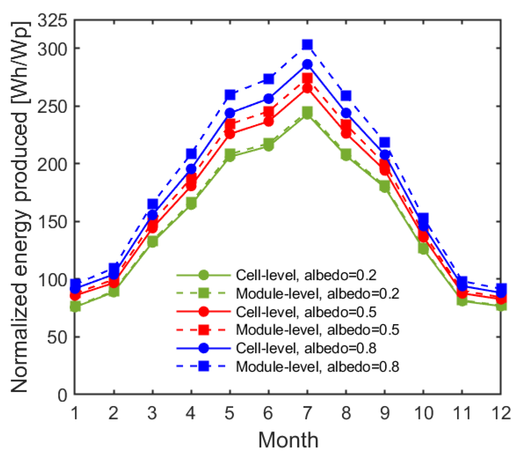
The energy produced along the year normalized to peak power is shown in Figure 4. Here, it can be inferred that using a module-level strategy to evaluate the irradiance dictated by albedo reflection on the rear side leads to an overestimation in power production increasing with ρ g , the origin of which can be explained as follows. As correctly determined by the novel approach, the albedo irradiance landing on the rear side is nonuniform, and depends on the specific position of the cell relative to the ground. Since the cells are electrically connected in series, the overall power output of the module is limited by the cell receiving the lowest irradiance due to its less favorable position with respect to the ground—a mechanism that is not accounted for in the module-level strategy. The irradiance mismatch among cells becomes more significant at higher albedo and during summer months, where the amount of solar irradiance impinging on the rear side can reach up to 30% of the total irradiance collected by the module.
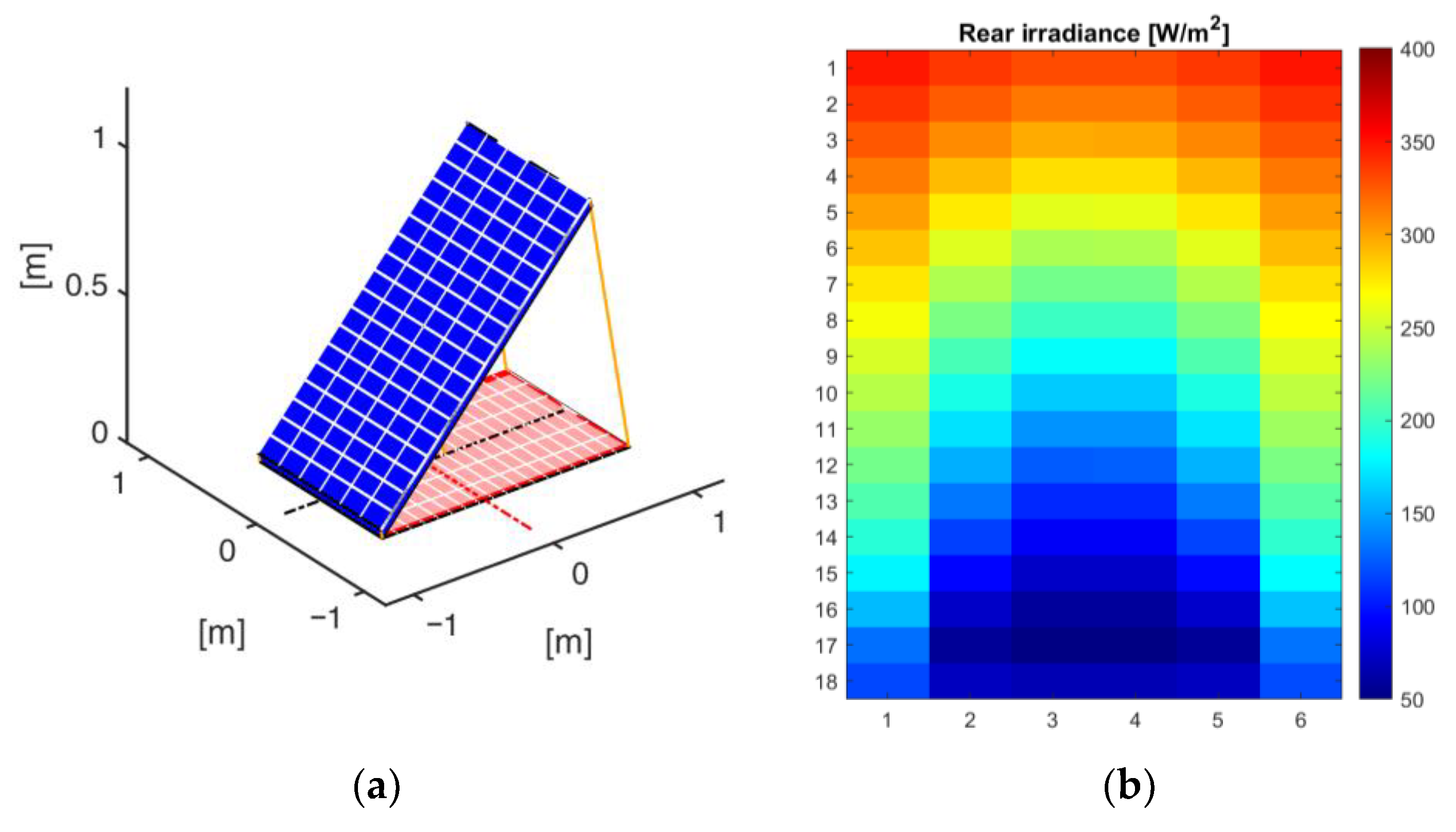
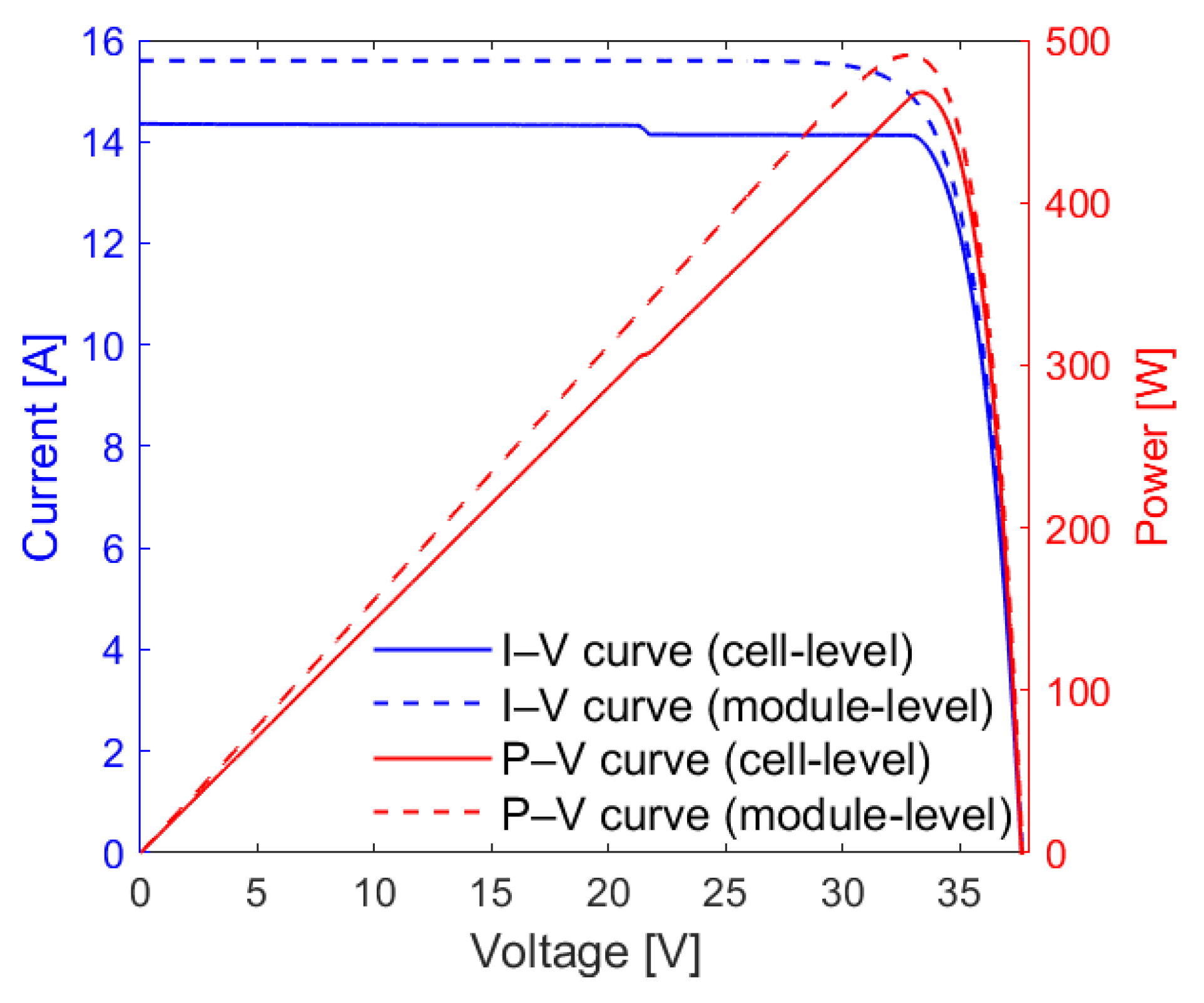
The above considerations are also supported by Figure 5 and Figure 6. Figure 5 illustrates the 3D scenario drawn by Matlab within our tool (Figure 5a) and the total irradiance distribution over the rear surface computed with the proposed semi-analytical modeling methodology (Figure 5b) on 15 June at 13:00, when the shadow of the module is projected onto the ground on the back side. Figure 6 shows the I– V and the P– V characteristics determined with both the proposed tool and the simplified module-level variant. It can be seen that the module-level strategy overestimates the MPP by 5% compared to our approach. Again, this discrepancy arises from the assumption that all the rear sides of the cells collect identical irradiance; in reality, the cells located close to the ground receive less albedo (and thus total) irradiance than those located on the module top (Figure 5b). Such a nonuniform irradiance distribution leads to current mismatch; consequently, in each submodule, the MPP is defined by the minimum irradiance hitting the rear (i.e., by the weakest cell), and not by the common (mean) value predicted by a simplified module-level approach. It can be inferred that each submodule in principle exhibits a different minimum irradiance, which leads to a stepped I– V characteristic due to the activation of bypass diodes.

3.2. Comparison with State-of-the-Art Approaches

The proposed tool was also compared with two state-of-the-art counterparts, namely, the earlier version of it [27] (using the fully analytical irradiance model presented in [26]) and pvlib [29], widely adopted within the PV research and engineering community due to its open-source nature and comprehensive set of models.
As mentioned before, the only difference between the novel tool and [27] lies in the albedo irradiance model, whereas the evaluation of beam and sky-diffuse irradiances, as well as the circuit-based cell-level unit, are identical in practice.
Figure 7a shows the realistic 3D Sun-module-shadow scenario for the albedo irradiance evaluation used by the proposed tool, where a finite-length module (casting a finite-length shadow) is considered, and the relative position of the Sun with respect to the module is properly evaluated.
Figure 7b illustrates the view-factor-based approach proposed in [26] and implemented in [27] to compute the albedo irradiance. Although this method was conceived and developed to correct a major theoretical flaw present in previous methods (where the impact of the view factor between shaded ground and the sky was neglected), it still lacks full accuracy, as it relies on a simplified 2D (i.e., infinite-length) description of the Sun-module-shadow system. Within such a representation, the Sun is always seen by the front surface, the position of the Sun and the direction of the solar rays are defined solely by the altitude α, and the module position is characterized only by the tilt angle β. As a result, the rear-ground view factors, calculated using the Hottel cross-string rule [22,42], depend exclusively on α and β. In addition, the model in [26] inherently assumes that the albedo irradiance is uniform over the front and rear sides of the cells (module-level strategy).
In pvlib [29], the beam and the sky-diffuse irradiances are determined as in the proposed approach and its former version [27]. Instead, the evaluation of the albedo reflected irradiance relies on the quasi-3D representation of the Sun-module-shadow scenario illustrated in Figure 7c, where the Sun describes a 3D trajectory, and the relative position of the Sun with respect to the module is well represented, but the view factors are computed using 2D formulations that intrinsically assume infinite-length module and shadow. Similar to [27], also in [29] a module-level strategy is applied, that is, there is only one value for the albedo-induced irradiance landing on the front side, and only one value for that hitting the rear side. The view factors are computed using the pvfactors engine [43].
Lastly, it is worth recalling that, unlike [27,29], the proposed irradiance modeling approach features a cell-level granularity for the albedo reflection. This distinction is not reflected in Figure 7, whose sole purpose is to illustrate the improved representation in terms of Sun-module-shadow scenario.
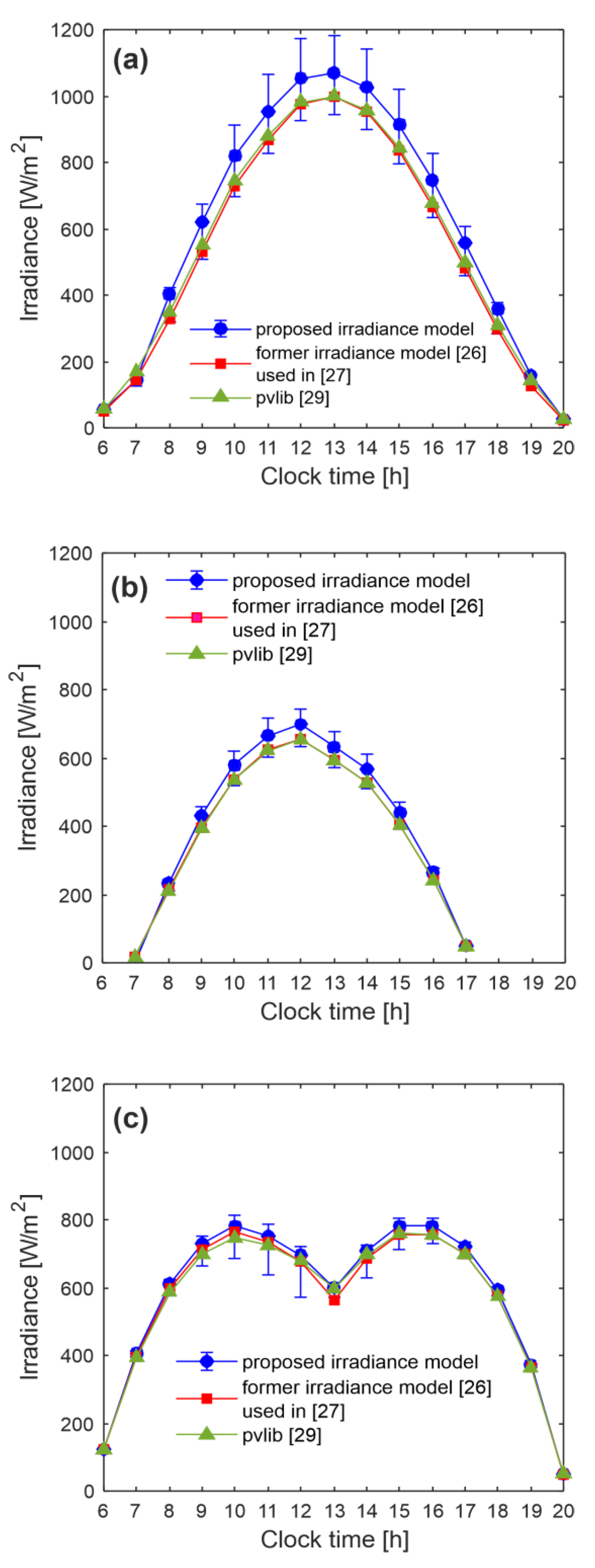
Figure 8 shows the total irradiance (sum of front and rear irradiances) collected by the module, as computed by the proposed semi-analytical approach [27,29], for three cases, namely,
  • South-oriented module tilted at β = 30° on 15 June (Figure 8a);
  • South-oriented module tilted at β = 30° on 15 February (Figure 8b);
  • Vertical (β = 90°) module with front side oriented to West on 15 June (Figure 8c).
  • with the module being always assumed installed in Naples; a ground albedo ρ g = 0.5 was considered for all cases. It is worth noting that vertical configurations are widely adopted in agrivoltaics, where the bifacial module can benefit from receiving solar irradiance on both sides throughout the day, as demonstrated in [27].
Using our cell-level approach for the evaluation of the albedo irradiances hitting front and rear sides of the cells, each cell receives a specific total irradiance. Hence, in Figure 8 we show the mean value of the total irradiance across all cells in the module against clock time, as well as vertical bars representing the range of irradiance values across the cells, with the upper and lower bounds being the maximum irradiance (collected by the cell receiving the highest albedo component) and the minimum one (associated with the cell receiving the lowest albedo component); therefore, the length of the bars is intended to be illustrative of the albedo-dictated irradiance nonuniformity across cells. Obviously, for [27,29], where a uniform albedo irradiance is assumed, the same total irradiance is shared among all cells.
Figure 8a shows that the irradiances computed by [27,29] are almost identical throughout the entire day. Making use of the more accurate cell-level irradiance model, it is found that (i) the albedo reflection on the rear side is markedly nonuniform, resulting in a significant spatial variation in the total irradiance; (ii) refs. [27,29] provide irradiance values perceptibly lower than the mean ones predicted by the proposed model, since the latter correctly accounts for the finite lengths of the module and the shadow it casts, so that the rear sides of the cells see more lateral unshaded ground. Instead, this is not captured by [27,29] due to their simplified approximation of infinite-length module and shadow.
In Figure 8b, again [27,29] virtually coincide. Although the albedo contribution plays a minor role in absolute terms (the Sun is lower in the sky and the shadows are wider), still in relative terms the albedo-induced nonuniformity is significant, and [27,29] underestimate the mean irradiance.
In Figure 8c, the albedo irradiance plays a marginal role with respect to the sky-diffuse counterpart because the module is vertical and its surfaces see the sky dome better than the ground; as a consequence, refs. [27,29] do not significantly underestimate the mean irradiance values computed by the novel approach.
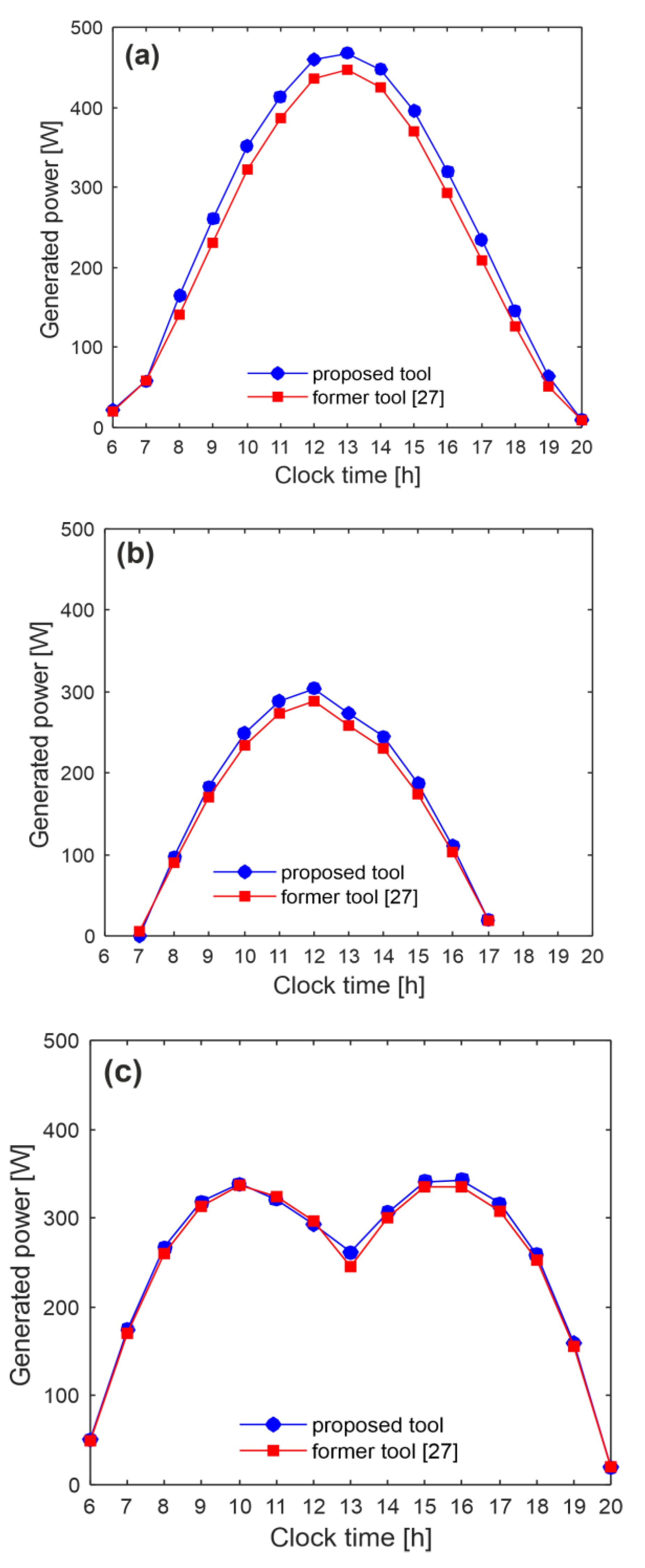
Figure 9 compares the generated maximum power computed by our tool and its earlier version [27] throughout the day for the aforementioned cases. It is worth recalling that the circuit-based cell-level blocks for the evaluation of the I– V curves—fed with the front and rear irradiances—are identical in both tools, and that all simulations are performed assuming a uniform cell temperature of 25°C, and absence of partial shading and malfunctioning cells. We chose not to involve the open-source pvlib library in this analysis for the following reason. In pvlib, the I– V characteristics are simulated using an aggregated module-level single-diode model, which thus does not support independent parameter sets for individual cells; on the other hand, partial shading can in principle be treated by splitting the module into various portions, calculating the I– V curve for each portion under different irradiances, and subsequently combining the curves to produce the overall module characteristic [44]. Such an approach suffers from lack of accuracy with respect to our circuit-based cell-level strategy; therefore, a direct comparison of the predicted power would not be methodologically sound, as any discrepancy would result from the combined effect of differences in both irradiance modeling and electrical simulation, whose individual contributions are impossible to isolate (conflation problem).
Figure 9a shows that the previous version of our tool [27] underestimates the power production. This behavior can be explained by referring to Figure 8a: on one hand, the total irradiance determined in [27] is lower than the mean value predicted by the novel tool, which correctly captures the laterally finite shadow, but on the other hand the least irradiated cells tend to degrade the MPP (mismatch loss). For this specific case, the first mechanism prevails over the second. A similar trend is observed in Figure 9b, even though the shadows along the day are wider and the albedo reflection plays a less relevant role. For the vertical module with a West-oriented front side (Figure 9c), the above mechanisms balance each other, so that the power productions virtually coincide.

3.3. Guidelines for PV Engineers and System Designers

The choice among the compared approaches should be driven by the geometric complexity of the installation under investigation and the required level of physical fidelity.
The proposed high-resolution tool is recommended whenever spatial nonuniformities in irradiance are expected to play a significant role. This includes albedo-dictated uneven irradiance distributions, partial shading from architectural elements, localized soiling or snow coverage, defective cells, and any other condition inducing mismatch at the cell level. For instance, the method can be particularly advantageous for standalone modules or short rows, such as rooftop systems, building-integrated PV applications, PV canopies, and agrivoltaic layout with sparse spacing, where the edge effect can be pronounced and the assumption of infinite-length rows becomes inadequate.
The earlier version of our tool [27], which offers reduced computational burden for the irradiance evaluation, represents a suitable compromise when mismatch due to partial shading or faulty cells is expected, particularly long rows are analyzed, and the albedo reflection plays a minor role (e.g., in long-row vertical installations for agrivoltaics).
The pvlib library [29] is well suited for large-scale energy yield estimation, preliminary design studies, and scenarios in which irradiance nonuniformities are limited or of secondary importance so that cell-level granularity is unnecessary.

4. Effect of the Ground Clearance

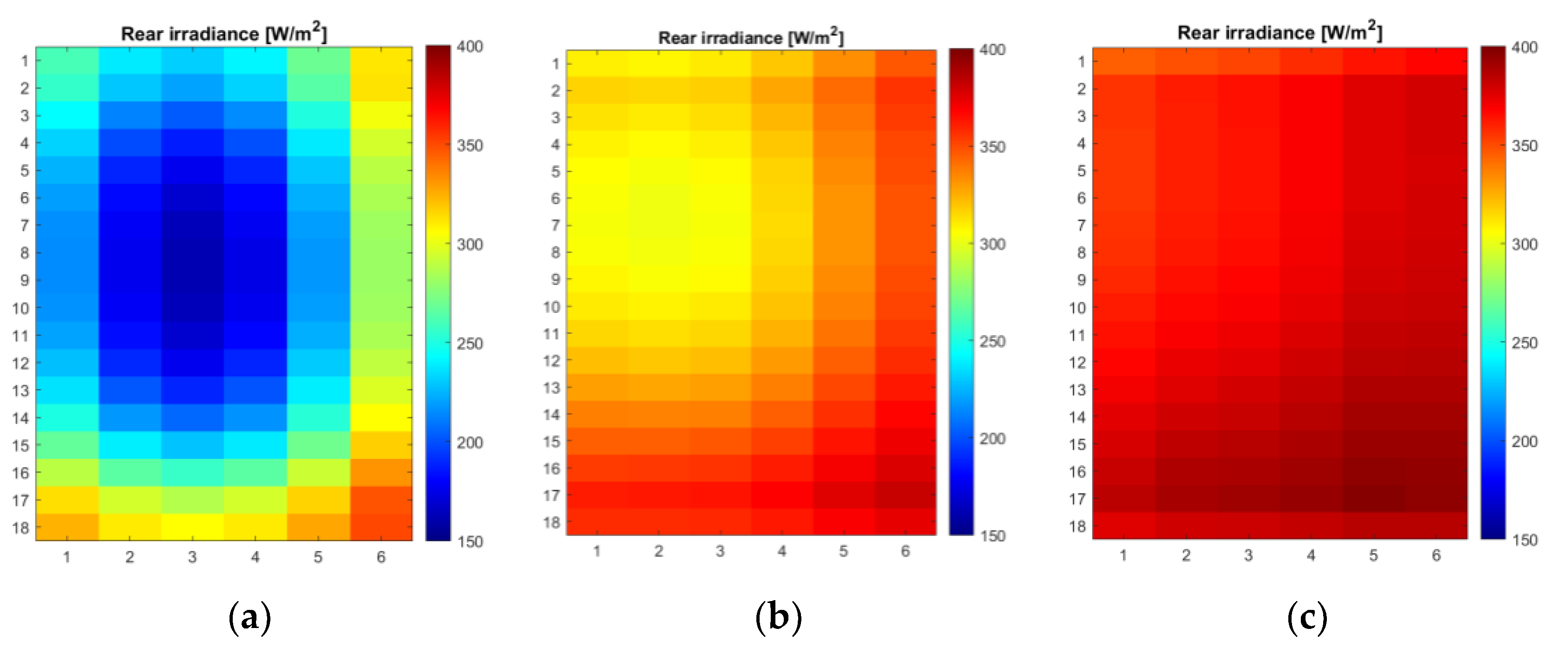
In this section we show that our tool is also suited to account for a non-zero ground clearance d. The same 108-cell module as in Section 3 was assumed to be horizontally installed (β = 0°) and oriented to South, on 15 June at 12:00, and an albedo ρ g = 0.5 was applied. Figure 10 shows the rear-side irradiance distribution for d = 0.5 m (Figure 10a), 1 m (Figure 10b), and 1.5 m (Figure 10c), as computed with the presented semi-analytical modeling strategy. For d = 0.5 m, the central module area is poorly illuminated, as the shaded ground lies directly beneath the module in close proximity to its rear surface. When d = 1 m, the weakly-irradiated area moves towards the upper-left module portion; in this case, the shaded ground is farther away, leading to an increase in the total irradiance and a reduction in the albedo-induced mismatch. For d = 1.5 m, the irradiance becomes nearly uniform across the rear side, with values comparable to the maximum reached at d = 1 m, that is, the albedo-induced mismatch has vanished.

5. Assessment of the Albedo-Induced Mismatch Losses

In this section, we present simulation results aimed at quantifying the impact of albedo-induced irradiance mismatch losses for different installation configurations. The same module as in Section 3 was once again used as a case study. The selected day was 15 June, and the applied albedo ρ g was 0.5. The configurations are in order:
  • South-oriented front side, tilt angle β = 30° (denoted as S-30).
  • West-oriented front side, vertical installation (β = 90°) (W-90).
  • East-oriented front side, vertical installation (E-90).
The mismatch loss was computed at each clock time according to
M l o s s % = 1 P c e l l- l e v e l P m o d u l e- l e v e l 100
where P c e l l- l e v e l is the maximum power calculated through the proposed tool, and P m o d u l e- l e v e l is the maximum power computed with its simplified module-level variant defined in Section 3.1.
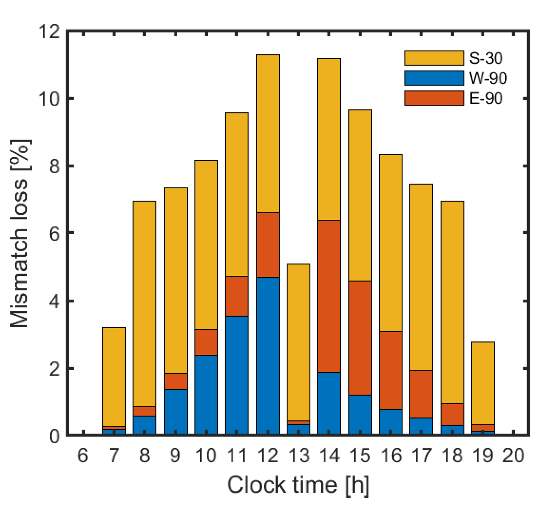
Figure 11 shows the losses along the whole day in the form of bars. Each sub-bar color represents a specific installation, with M l o s s being given by the sub-bar height. As can be seen, S-30 is affected by a marked, almost constant, albedo-induced mismatch loss throughout the day; this is mainly dictated by the vertical nonuniformity in the albedo reflection over the rear, that is, the rear sides of the cells positioned on the module bottom receive only a little portion of the light reflected from the unshaded ground due to the close proximity to the shadow, whereas the rear sides of the top cells benefit from a better view of the unshaded ground. A slightly higher M l o s s (~6%) is observed in the early morning (8:00 to 10:00) and late afternoon (16:00 to 18:00), as also the edge effect takes place.
By contrast, the vertically-mounted West- and East-oriented installations generally exhibit superior performance because (i) the rear surfaces have greater exposure to the sky dome and (ii) the surface seeing the module-generated shadow has a reduced view of the ground, which limits the contribution of the albedo reflection. It can be observed that the W-90 configuration suffers from a higher M l o s s in the morning than in the afternoon, which can be explained as follows. In the morning, detrimental effects occur on both module sides: (i) albedo irradiance nonuniformity on the front side, which sees the shadow cast on the ground, and (ii) a reduction in view factors due to the metal frame on the rear side, where the solar rays land. Conversely, in the afternoon, only the rear surface is affected by the above mechanisms, as the solar rays impinge on the front surface. The opposite behavior is observed for the E-90 configuration: in the morning, the undesired mechanisms affect only the rear side, whereas in the afternoon they separately affect both surfaces.

6. Experimental Validation

This section presents the experimental validation of the proposed tool. To isolate and assess the rear-side irradiance contribution, a controlled emulation strategy was adopted. Instead of employing a commercial bifacial module, a monofacial module was installed oriented to North with a tilt angle of β = 150°. Under this configuration, the active (front) surface of the monofacial module effectively replicates the exposure conditions of the rear side facing the ground of a bifacial module inclined by 30° with an ideally obscured front oriented due South. This approach was conceived to provide a clean and physically consistent validation framework for the most innovative part of the proposed tool.
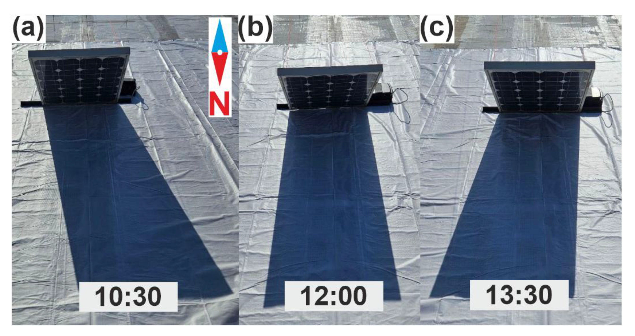
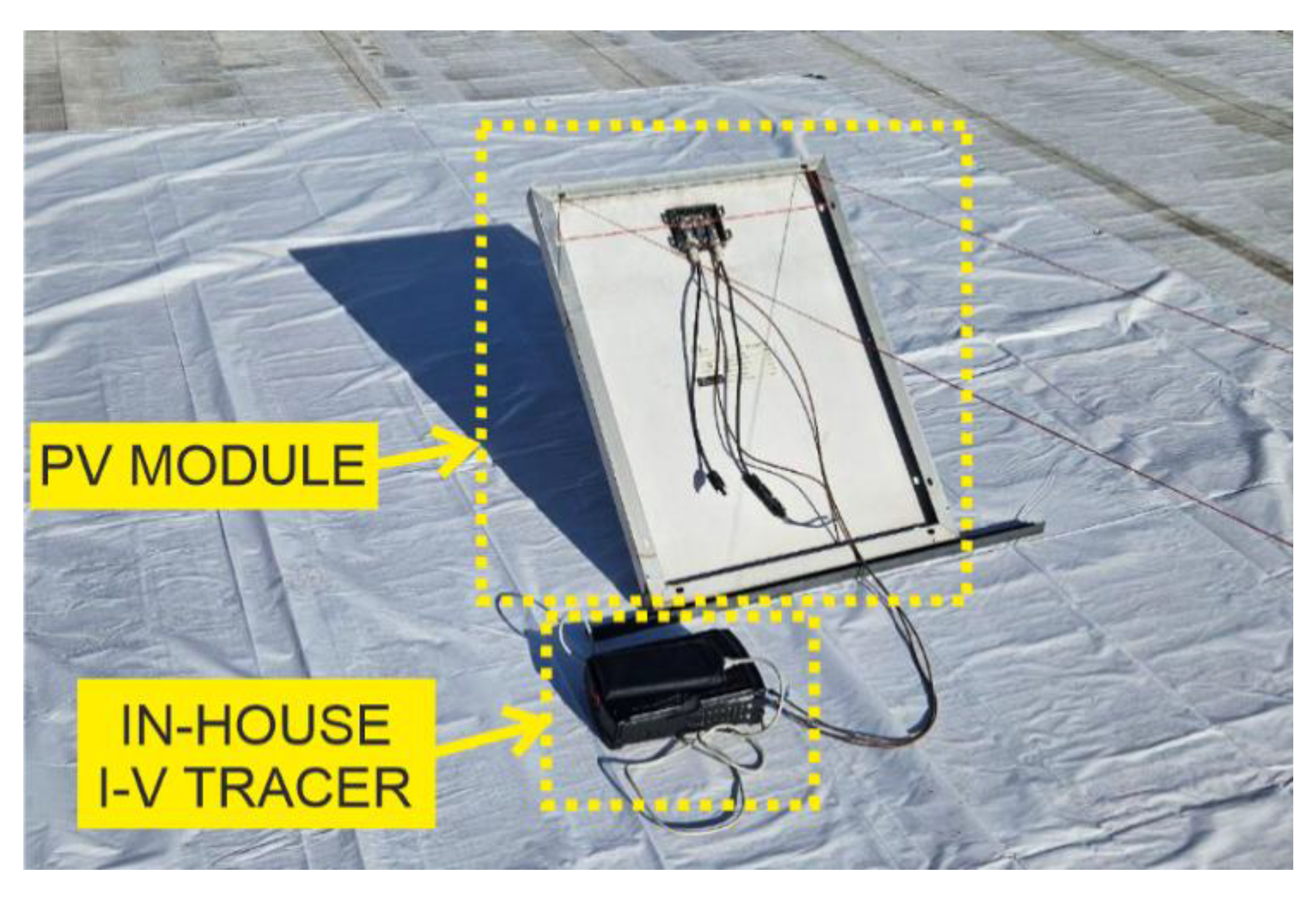
The experimental campaign was carried out at the Department of Electrical Engineering and Information Technology at the University of Naples Federico II. The setup comprises a 50 Wp monofacial PV module ET-M54050 embedding 20 cells and two bypass diodes [45]. The setup is shown in Figure 12. To reproduce a high-albedo scenario, a reflective white sheet was placed on the ground. The experiment was carried out by measuring the I– V characteristics of the module during the day through a curve tracer prototyped in-house [46]. The measurements were performed on 23 January 2025, under clear-sky conditions at three distinct times, namely, 10:30, 12:00, and 13:30, resulting in different shadow configurations, as shown in Figure 13.
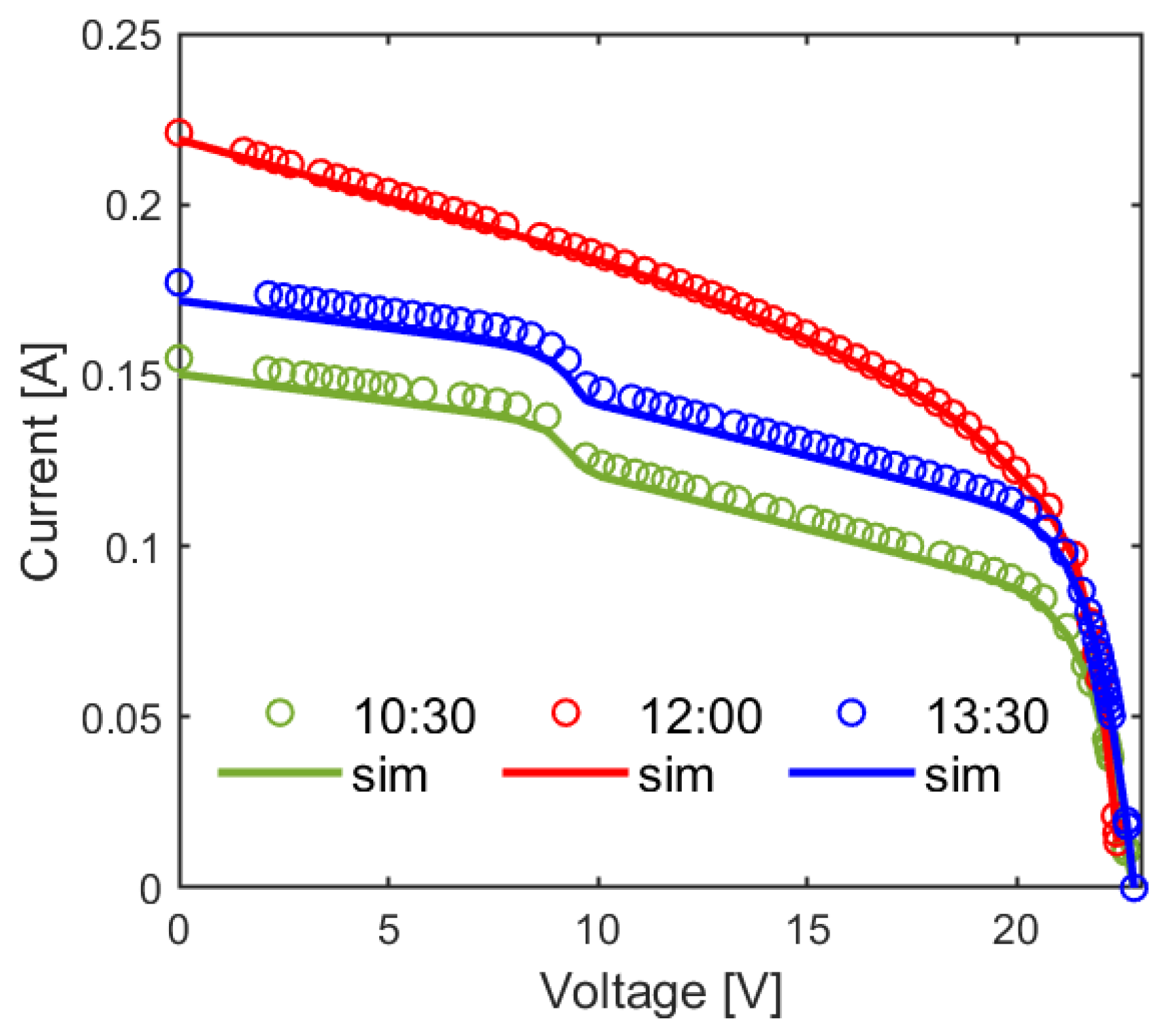
The measured I– V characteristics were compared to those obtained with our tool by deactivating the photogenerated currents on the front in (11) and imposing a bifaciality factor φ = 1. As can be inferred from Figure 13b, at 12:00 the shadow is vertically aligned with the central axis of the module. The bottom-centered cells receive less irradiance than those at the top corners due to the limited view factors to the unshaded ground, leading to an irradiance distribution similar to the one depicted in Figure 5b. Consequently, the short-circuit current of the entire module is limited to the current photogenerated by the least-irradiated cell. It is worth noting that the two submodules experience symmetrical irradiance distribution, and the I– V curve does not exhibit the typical ladder-shape occurring in case of current mismatch between submodules and due to the action of the bypass diodes. Conversely, in the early morning and in the afternoon, the shadow is not aligned with the axis of symmetry of the module. In this condition, the two submodules experience a different irradiance distribution. In particular, the submodule located close to the shadow has a larger number of less-irradiated cells. As a result, the bypass diode protecting the weakest submodule is activated, leading to the occurrence of a ladder shape in the I– V characteristic. As shown in Figure 14, the curves corresponding to 10:30 and 13:30 exhibit two regions with different slopes. It is worth mentioning that the slope of the I– V curve close to the short-circuit current corresponds to the R s h of the least-irradiated cell [47]. Additionally, in a module affected by mismatch, the slope of the I– V curve becomes less pronounced when the number of poorly-irradiated cells decreases. Accordingly, the region 0 V–10 V corresponds to the submodule with a high number of more irradiated cells, whereas the region 10 V– V o c corresponds to the submodule with a low number of less-irradiated cells.
Simulation results show a good agreement with experimental data, the error being lower than 3%.

7. Conclusions

In this work, we have presented a tool for the accurate assessment of the power production of bifacial PV modules. The methodological novelty lies in the refined evaluation of the albedo irradiance reflected from the ground, which is numerically computed within a realistic 3D Sun-module-shadow geometry using a cell-level view-factor-based approach. Unlike existing methods, the proposed framework captures both vertical and lateral nonuniformities in the albedo irradiance distribution on the module sides. The irradiances hitting the front and rear sides of the cells are subsequently fed to a circuit-based block—likewise structured at cell-level granularity—for the evaluation of the MPP at chosen time instants. A simplified variant of the tool has also been developed, in which a uniform albedo reflection is determined over the module surfaces (traditional module-level approach); it has been demonstrated that this approximation leads to an appreciable overestimation of the power production, as it neglects albedo-induced mismatch losses. An extensive simulation comparison against state-of-the-art approaches—including the previous version of the tool—has been performed, leading to the conclusion that the proposed approach is the preferred choice when pronounced nonuniformity in the albedo reflection is expected, as in standalone modules or short row configurations under medium-to-high albedo conditions. Moreover, as in its previous version, the proposed tool allows handling partial architectural shading, localized snow coverage, bird droppings, and defective cells, which broadens its applicability to realistic operating scenarios. The simulation outcomes have further revealed that the mismatch loss due to albedo on the rear in low-tilt South-oriented bifacial modules can reach up to 6% in summer under medium-albedo conditions. Conversely, vertical West- or East-oriented modules are less affected by mismatch losses because the relative contribution of the albedo irradiance on the rear surface becomes less important compared to the sky-diffuse counterpart. Lastly, an outdoor experimental campaign has been conducted to verify the accuracy of the proposed approach.

Author Contributions

Conceptualization, M.D.R., G.S., P.G. and S.D.; methodology, M.D.R., P.G. and V.d.; software, M.D.R.; validation, M.D.R., G.S. and P.G.; formal analysis, M.D.R. and P.G.; investigation, M.D.R., G.S. and P.G.; writing—original draft preparation, M.D.R.; writing—review and editing, M.D.R. and V.d.; visualization, P.G., S.D. and V.d.; supervision, S.D. and V.d. All authors have read and agreed to the published version of the manuscript.

Funding

This work has been supported by the Italian Ministry of Research (MUR) by means of the following grants: (i) PRIN2022-DOGPHOSS (cod. P20229FWZK), and (ii) PRIN2020–HOTSPHOT (cod. 2020LB9TBC).

Institutional Review Board Statement

Not applicable.

Informed Consent Statement

Not applicable.

Data Availability Statement

The data are available upon request to the corresponding author.

Conflicts of Interest

The authors declare no conflicts of interest.

References

  1. Saggese, G.; De Riso, M.; Matacena, I.; Guerriero, P.; Daliento, S. Dynamic bypass controller with regenerative feedback for hot-spot-free PV modules. IEEE J. Photovolt. 2025, 15, 879–885. [Google Scholar] [CrossRef]
  2. De Riso, M.; Saggese, G.; Guerriero, P.; Daliento, S. A Novel DC–DC Converter Design for On-Field Impedance Spectroscopy on Individual Photovoltaic Modules. In Proceedings of the 2025 IEEE 53rd Photovoltaic Specialists Conference (PVSC), Montreal, QC, Canada, 8–13 June 2025; pp. 1501–1503. [Google Scholar]
  3. Liang, T.S.; Pravettoni, M.; Deline, C.; Stein, J.S.; Kopecek, R.; Singh, J.P.; Luo, W.; Wang, Y.; Aberle, A.G.; Khoo, Y.S. A review of crystalline silicon bifacial performance characterisation and simulation. Energy Environ. Sci. 2023, 12, 116–148. [Google Scholar] [CrossRef]
  4. Garrod, A.; Ghosh, A. A review of bifacial solar photovoltaic applications. Front. Energy 2023, 17, 704–726. [Google Scholar] [CrossRef]
  5. Zhong, J.; Zhang, W.; Xie, L.; Zhao, O.; Wu, X.; Zeng, X.; Guo, J. Development and challenges of bifacial photovoltaic technology and application in buildings: A review. Renew. Sustain. Energy Rev. 2023, 187, 113706. [Google Scholar] [CrossRef]
  6. Yakubu, R.O.; Mensah, L.D.; Quansah, D.A.; Adaramola, M.S. A systematic literature review of the bifacial photovoltaic module and its applications. J. Eng. 2024, 2024, e12421. [Google Scholar] [CrossRef]
  7. Mahim, T.M.; Rahim, A.H.M.A.; Mosaddequr Rahman, M. Review of mono- and bifacial photovoltaic technologies: A comparative study. IEEE J. Photovolt. 2024, 14, 375–396. [Google Scholar] [CrossRef]
  8. Belsky, A.A.; Ngyen, V.T.; Sheikhi, M.H.; Starshaia, V.V. Analysis of specifications of bifacial photovoltaic panels. Renew. Sustain. Energy Rev. 2025, 224, 116092. [Google Scholar] [CrossRef]
  9. Krainer, D.M.; Rennhofer, M.; Mittal, A.; Ujvari, G.; Zamini, S.; Weihs, P.; Dorninger, M. Bifacial photovoltaic module performance in correlation to cloud conditions, sun spectrum, and irradiance enhancement. Sol. Energy 2025, 285, 113110. [Google Scholar] [CrossRef]
  10. Ogliari, E.; Dolara, A.; Mazzeo, D.; Lazzari, L.; Leva, S. A simplified multi-physics approach for bifacial photovoltaic modules: Theory and validation of peculiar module layout. Energy Convers. Manag. X 2026, 30, 101499. [Google Scholar] [CrossRef]
  11. Sahu, P.K.; Roy, J.N.; Chakraborty, C. Performance assessment of a bifacial PV system using a new energy estimation model. Sol. Energy 2023, 262, 111818. [Google Scholar] [CrossRef]
  12. Durusoy, B.; Ozden, T.; Akinoglu, B.G. Solar irradiation on the rear surface of bifacial solar modules: A modeling approach. Sci. Rep. 2020, 10, 13300. [Google Scholar] [CrossRef] [PubMed]
  13. Ayala Pelaez, S.; Deline, C.; Greenberg, P.; Stein, J.S.; Kostuk, R.K. Model and validation of single-axis tracking with bifacial PV. IEEE J. Photovolt. 2019, 9, 715–721. [Google Scholar] [CrossRef]
  14. McIntosh, K.R.; Abbott, M.D.; Sudbury, B.A.; Meydbray, J. Mismatch loss in bifacial modules due to nonuniform illumination in 1-D tracking systems. IEEE J. Photovolt. 2019, 9, 1504–1512. [Google Scholar] [CrossRef]
  15. McIntosh, K.R.; Abbott, M.D.; Sudbury, B.A. The optimal tilt angle of monofacial and bifacial modules on single-axis trackers. IEEE J. Photovolt. 2022, 12, 397–405. [Google Scholar] [CrossRef]
  16. Tsuchida, S.; Tsuno, Y.; Sato, D.; Oozeki, T.; Yamada, N. Albedo-dependent bifacial gain losses in photovoltaic modules with rear-side support structures. IEEE J. Photovolt. 2023, 13, 938–944. [Google Scholar] [CrossRef]
  17. Ernst, M.; Liu, X.; Asselineau, C.-A.; Chen, D.; Huang, C.; Lennon, A. Accurate modelling of the bifacial gain potential of rooftop solar photovoltaic systems. Energy Convers. Manag. 2024, 300, 117947. [Google Scholar] [CrossRef]
  18. Mouhib, E.; Fernández-Solas, Á.; Pérez-Higueras, P.J.; Fernández-Ocaña, A.M.; Micheli, L.; Almonacid, F.; Fernández, E.F. Enhancing land use: Integrating bifacial PV and olive trees in agrivoltaic systems. Appl. Energy 2024, 359, 122660. [Google Scholar] [CrossRef]
  19. Petersen, A.J.; Frimannslund, I. A fast and accurate raytracing approach for assessing photovoltaic performance of mono and bifacial modules in complex irradiance conditions. E3S Web Conf. 2024, 562, 05001. [Google Scholar]
  20. Kim, B.; Kang, I.; Jang, E.; Jang, H.; Hwang, S.; Lee, H.; Shin, M. Accurate energy yield simulation of a carport system using the ray-tracing method. J. Power Sources Adv. 2025, 31, 100164. [Google Scholar] [CrossRef]
  21. Abotaleb, A.; Abdallah, A. Performance of bifacial-silicon heterojunction modules under desert environment. Renew. Energy 2018, 127, 94–101. [Google Scholar] [CrossRef]
  22. Gu, W.; Ma, T.; Li, M.; Shen, L.; Zhang, Y. A coupled optical-electrical-thermal model of the bifacial photovoltaic module. Appl. Energy 2020, 258, 114075. [Google Scholar] [CrossRef]
  23. Deline, C.; Ayala Pelaez, S.; MacAlpine, S.; Olalla, C. Estimating and parameterizing mismatch power loss in bifacial photovoltaic systems. Prog. Photovolt. Res. Appl. 2020, 28, 691–703. [Google Scholar] [CrossRef]
  24. Rouholamini, M.; Chen, L.; Wang, C. Modeling, configuration, and grid integration analysis of bifacial PV arrays. IEEE Trans. Sustain. Energy 2021, 12, 1242–1255. [Google Scholar] [CrossRef]
  25. Lee, C.; Agrawal, R.; Sanchez, G.; Bermel, P. Simulation and design aspects of a bifacial single-axis tracker across North America, to enhance the efficiency of solar radiation utilization. In Proceedings of the IEEE 52nd Photovoltaic Specialist Conference (PVSC), Seattle, WA, USA, 9–14 June 2024; pp. 0523–0525. [Google Scholar] [CrossRef]
  26. d’Alessandro, V.; Daliento, S.; Dhimish, M.; Guerriero, P. Albedo reflection modeling in bifacial photovoltaic modules. Solar 2024, 4, 660–673. [Google Scholar] [CrossRef]
  27. d’Alessandro, V.; Daliento, S.; Dhimish, M.; Guerriero, P. A tool for a fast and accurate evaluation of the energy production of bifacial photovoltaic modules. Solar 2025, 5, 2. [Google Scholar] [CrossRef]
  28. Benbba, R.; Akhsassi, M.; El Mouden, H.; Wifaya, A.; Outzourhit, A. View factors approach for bifacial photovoltaic array modeling: Bifacial gain sensitivity analysis. J. Sol. Energy Eng. 2025, 147, 021008. [Google Scholar] [CrossRef]
  29. pvlib. Computer Software. 2025. Available online: https://pvlib-python.readthedocs.io/en/latest/ (accessed on 13 January 2025).
  30. Kang, J.; Jang, J.; Reise, C.; Lee, K. Practical comparison between view factor method and ray-tracing method for bifacial PV system yield prediction. In Proceedings of the 36th European PV Solar Energy Conference and Exhibition (EU PVSEC), Marseille, France, 9–13 September 2019; pp. 1474–1479. [Google Scholar] [CrossRef]
  31. Grommes, E.-M.; Schemann, F.; Klag, F.; Nows, S.; Blieske, U. Simulation of the irradiance and yield calculation of bifacial PV systems in the USA and Germany by combining ray tracing and view factor model. EPJ Photovolt. 2023, 14, 11. [Google Scholar] [CrossRef]
  32. Coppola, M.; Dannier, A.; Fedele, E.; Saggese, G.; Guerriero, P. Design and control of an enhanced grid-tied PV CHB inverter. Energies 2025, 18, 2056. [Google Scholar] [CrossRef]
  33. PVGIS. Online Tool. 2025. Available online: https://joint-research-centre.ec.europa.eu/photovoltaic-geographical-information-system-pvgis_en (accessed on 4 March 2024).
  34. Liu, B.Y.H.; Jordan, R.C. A rational procedure for predicting the long-term average performance of flat-plate solar-energy collectors—With design data for the U.S., its outlying possessions and Canada. Sol. Energy 1963, 7, 53–74. [Google Scholar] [CrossRef]
  35. Perez, R.; Ineichen, P.; Seals, R.; Michalsky, J.; Stewart, R. Modeling daylight availability and irradiance components from direct and global irradiance. Sol. Energy 1990, 44, 271–289. [Google Scholar] [CrossRef]
  36. Reindl, D.T.; Beckman, W.A.; Duffie, J.A. Evaluation of hourly tilted surface radiation models. Sol. Energy 1990, 45, 9–17. [Google Scholar] [CrossRef]
  37. LTspice XVII. Computer Software. 2025. Available online: https://www.analog.com/en/resources/design-tools-and-calculators/ltspice-simulator.html (accessed on 13 January 2025).
  38. Guerriero, P.; Codecasa, L.; d’Alessandro, V.; Daliento, S. Dynamic electro-thermal modeling of solar cells and modules. Sol. Energy 2019, 179, 326–334. [Google Scholar] [CrossRef]
  39. King, D.L.; Boyson, W.E.; Kratochvill, J.A. Photovoltaic Array Performance Model. Sandia Report, SAND2004-3535. Available online: https://www.osti.gov/servlets/purl/919131 (accessed on 13 January 2025).
  40. Guo, B.; Javed, W. Effect of incidence angle on PV soiling loss. Sol. Energy 2024, 269, 112298. [Google Scholar] [CrossRef]
  41. Suntech. STP430S-C54/Nmhm+, Datasheet. Available online: https://www.suntech-power.com (accessed on 13 January 2025).
  42. Appelbaum, J. Bifacial photovoltaic panels field. Renew. Energy 2016, 85, 338–343. [Google Scholar] [CrossRef]
  43. Anoma, M.A.; Jacob, D.; Bourne, B.C.; Scholl, J.A.; Riley, D.M.; Hansen, C.W. View factor model and validation for bifacial PV and diffuse shade on single-axis trackers. In Proceedings of the IEEE 44th Photovoltaic Specialist Conference (PVSC), Washington, DC, USA, 25–30 June 2017. [Google Scholar] [CrossRef]
  44. Dobos, A.P. PVWatts Version 5 Manual. Available online: https://docs.nrel.gov/docs/fy14osti/62641.pdf (accessed on 13 January 2025).
  45. ET-Solar. ET-M54050, Datasheet. Available online: https://client.lpelectric.ro/doc/et_solar/etm54050.pdf (accessed on 13 January 2025).
  46. De Riso, M.; Hassan, S.; Guerriero, P.; Dhimish, M.; Daliento, S. Enhanced photovoltaic panel diagnostics: Advancing a high-precision and low-cost I–V curve tracer. IEEE Trans. Instrum. Meas. 2024, 73, 9006110. [Google Scholar] [CrossRef]
  47. d’Alessandro, V.; Guerriero, P.; Daliento, S.; Gargiulo, M. A straightforward method to extract the shunt resistance of photovoltaic cells from current–voltage characteristics of mounted arrays. Solid-State Electron. 2011, 63, 130–136. [Google Scholar] [CrossRef]
Figure 1. Simulation diagram of the proposed tool, incorporating a code for the evaluation of the irradiance hitting the front and rear surfaces with a cell-level resolution, and a circuit-based cell-level block for the computation of IV characteristics at chosen clock times.
Solar 06 00015 g001
Figure 2. Representation of the view factors computed for both (a) the front and (b) the rear side of the module, for the particular case of solar rays impinging on the front. The i-th cell is highlighted in dark blue, the j-th cell is highlighted in orange, while the shadow cast by the j-th cell onto the ground is highlighted in light grey. Also indicated are the solar altitude α, the azimuth angle of the module ɣ, and the incidence angle between the solar rays and the normal to the module front θ. (c) Illustrative sketch of the approach adopted for the numerical evaluation (10) of the view factors used in the formulations of G a , i F and G a , i R .
Solar 06 00015 g002
Figure 3. SDM-based equivalent electric circuit of a cell embedded in a bifacial module.
Solar 06 00015 g003
Figure 4. Energy produced by a South-oriented 30°-tilted bifacial module normalized to peak power throughout a year, at different albedo (ρg) values. The dashed lines with squares refer to the traditional module-level strategy for the evaluation of the irradiance induced by albedo, whereas the solid curves with circles are determined with the proposed cell-level approach.
Solar 06 00015 g004
Figure 5. (a) Matlab-generated 3D scenario of a South-oriented 30°-tilted 108-cell bifacial module (depicted in blue) on June 15 at 13:00, including solar rays (solid orange lines) and shadow projected onto the ground (red); (b) corresponding total irradiance distribution over the rear side for a ground albedo ρg = 0.5.
Solar 06 00015 g005
Figure 6. IV (blue, left) and PV (red, right) characteristics of a South-oriented bifacial module tilted at β = 30° on 15 June at 13:00 with ρg = 0.5, obtained using the proposed tool (solid lines) and its simplified variant relying on a module-level strategy for the irradiance evaluation (dashed).
Solar 06 00015 g006
Figure 7. Schematic representation of the Sun-module-shadow scenario adopted to calculate the albedo-induced irradiance component in (a) our novel semi-analytical modeling approach, (b) our former fully analytical strategy presented in [26] and implemented in [27], and (c) pvlib [29].
Solar 06 00015 g007
Figure 8. Total irradiance collected by the cells belonging to a bifacial module installed in Naples against clock time: (a) front side oriented to South, tilt angle β = 30°, on 15 June; (b) front side oriented to South, tilt angle β = 30°, on 15 February; (c) front side oriented to West, vertical installation (β = 90°), on 15 June. The irradiance determined using the proposed approach (blue lines) is compared to the one computed with the former variant of the model (red lines with squares) and with the model embedded in pvlib (green lines with triangles). Concerning the curve obtained with the proposed model, the blue circles represent the mean values of the total irradiances across all cells, and the blue bars define the range of total irradiances collected by the cells. For all cases, a ground albedo ρg = 0.5 is considered.
Solar 06 00015 g008
Figure 9. Maximum power generated by a bifacial module installed in Naples against clock time: (a) front side oriented to South, tilt angle β = 30°, on 15 June; (b) front side oriented to South, tilt angle β = 30°, on 15 February; (c) front side oriented to West, vertical installation (β = 90°), on 15 June. The power determined with the proposed approach (blue lines with circles) is compared to the one computed with the former variant of our tool (red lines with squares). The corresponding total irradiances are reported in Figure 8.
Solar 06 00015 g009
Figure 10. Total rear-side irradiance computed for a horizontally-installed South-oriented module with an elevation from ground d equal to (a) 0.5 m, (b) 1 m, and (c) 1.5 m.
Solar 06 00015 g010
Figure 11. Hourly mismatch loss along 15 June for three different configurations: 30°-tilted bifacial module with South-oriented front side (orange), vertical module with West-oriented front side (blue), and vertical module with East-oriented front side (red).
Solar 06 00015 g011
Figure 12. The experimental setup consists of a monofacial PV module tilted at β = 150° and North oriented (ɣ = 180°), placed on a reflective white sheet to increase the albedo. The IV curves are measured by means of a curve tracer prototyped in-house.
Solar 06 00015 g012
Figure 13. Shadow projections of the PV module at different times, namely, (a) 10:30, (b) 12:00, and (c) 13:30.
Solar 06 00015 g013
Figure 14. Experimental IV curves (marked by circles) obtained at different times, namely, 10:30 (green), 12:00 (red), and 13:30 (blue), along with the corresponding characteristics simulated with the proposed tool (solid lines).
Solar 06 00015 g014
Table 1. Bifacial PV module specifications.
ParameterValue
Number of cells N108 (6 × 18)
Number of bypass diodes nbd3
Height Hm, length Lm, thickness dm1722 mm, 1134 mm, 30 mm
Width of the metal frame df30 mm
Bifaciality factor φ80%
PMAX@STC430 W
Voc@STC38.25 V
Isc@STC14.17 A
Disclaimer/Publisher’s Note: The statements, opinions and data contained in all publications are solely those of the individual author(s) and contributor(s) and not of MDPI and/or the editor(s). MDPI and/or the editor(s) disclaim responsibility for any injury to people or property resulting from any ideas, methods, instructions or products referred to in the content.