Article

The Influence of Alignment Degree on the Shrinkage Behavior of Sintered Nd-Fe-B Magnets

1
School of Materials Science and Engineering, Jiangxi University of Science and Technology, Ganzhou 341000, China
2
School of Electrical Engineering and Automation, Jiangxi University of Science and Technology, Ganzhou 341000, China
3
Jiangxi Provincial Key Laboratory of Maglev Technology, Ganzhou 341000, China
4
National Rare Earth Functional Materials Innovation Center, Ganzhou 341000, China
5
School of Mechanical and Electrical Engineering, Jiangxi University of Science and Technology, Ganzhou 341000, China
6
Jiangxi Yueci Rare Earth New Material Technology Co., Ltd., Ganzhou 341000, China
*
Author to whom correspondence should be addressed.
Magnetism 2026, 6(1), 12; https://doi.org/10.3390/magnetism6010012

Submission received: 17 December 2025 / Revised: 26 January 2026 / Accepted: 2 February 2026 / Published: 11 March 2026

Abstract

In this study, Nd-Fe-B magnets with different degrees of alignment were prepared by adjusting the strength of the alignment magnetic field. The mechanism of influence of alignment degree on the densification of magnets was systematically investigated. The shrinkage rates of the magnets after sintering were calculated, and the results showed that the unoriented magnets exhibited similar shrinkage in different directions, displaying isotropic shrinkage behavior. With the increase in the degree of alignment, the magnets showed significant differences in shrinkage across different directions, presenting anisotropic shrinkage characteristics. In addition, the microstructural analysis revealed that the alignment degree also exerted a certain influence on the micromorphology of the magnets. The grain size parallel to the c-axis was larger than that parallel to the a-axis, which indicates that the alignment degree plays a crucial role in the anisotropic densification of the Nd-Fe-B magnets.

1. Introduction

Sintered Nd-Fe-B permanent magnet materials exhibit broad application prospects in high-end fields due to their excellent magnetic properties and cost-effectiveness, as exemplified in areas such as new energy vehicles, wind power generation, and precision sensors [1,2]. Fabricated via the powder metallurgy process [3], these magnets undergo sintering at temperatures above 1000 °C. Due to their intrinsic properties, anisotropic shrinkage occurs in the magnets during the sintering process. This not only makes it difficult to control the dimensions of the final products, but also causes magnet deformation and even cracking, thereby reducing the yield rate [4]. Post-sintering machining is consequently required to trim the excess material, which generates a large quantity of waste magnets [5,6,7]. This problem not only increases production costs but also leads to a great waste of resources, which is detrimental to the development of sintered Nd-Fe-B materials. Therefore, reducing the anisotropic shrinkage caused by sintering has extremely important research value and significance for the conservation of rare earth resources and the development of an economic cycle [8].
The anisotropy of sintered Nd-Fe-B mainly originates from the external magnetic field applied during the orientation molding process, which induces the anisotropic arrangement of the main phase grains [9]. To investigate the relationship between sintering shrinkage behavior and aligned magnetic field, Liu et al. [10] compared the sintering shrinkage rates of green compacts prepared under magnetic field intensities of 0 T and 10 T. The research ascertained that the sintering shrinkage anisotropy may stem from particle orientation induced by high magnetic fields. Ni et al. [11] proposed that a higher aligned magnetic field optimizes the microstructure of magnets, rendering magnetic domain orientations more aligned with the applied field direction, and reinforcing the degree of orientation. Liu et al. [12] delved into the dynamics among deformation ratio, crystal orientation, and magnetic anisotropy in disproportionated Nd (Fe,Co)B, attesting that oriented forming can downgrade nucleation activation energy and foster preferential growth. Jong et al. [13] investigated the effects of shrinkage and grain size in Nd-Fe-B magnets parallel and perpendicular to the magnetic alignment direction, revealing that the sintering shrinkage parallel to the magnetic alignment direction was higher than that in the perpendicular direction. Meanwhile, grain growth was faster in the perpendicular direction, with grain sizes approximately 10% larger than those in the parallel direction. B Hugonnet et al. [14] leveraged a discrete element model (DEM) to demonstrate that shrinkage anisotropy arises from differences in mass transport, as a result of contact orientation. Akimitsu Ishii et al. [15] employed a phase-field model to affirm that the changes in neck curvature originated from surface anisotropy are critical factors determining neck growth and densification rates.
Although extensive research has been conducted on the anisotropic shrinkage behavior during sintering, shrinkage deformation induced by sintering remains an intractable problem. The influence of the degree of orientation of sintered Nd-Fe-B permanent magnet materials on anisotropic densification behavior is still not fully understood. It is therefore necessary to further explore the effect of the degree of orientation on their densification behavior. This study focuses on the influence of the change in contact angle between grains, which is induced by different aligned magnetic field intensities, on the densification behavior of Nd-Fe-B magnets. In this work, magnets with different alignment degrees were prepared by adjusting the intensity of the aligned magnetic field during the orientation molding process. The experimental results were then analyzed to investigate the effect of different degrees of orientation on the anisotropic shrinkage behavior during sintering.

2. Experimental Procedure

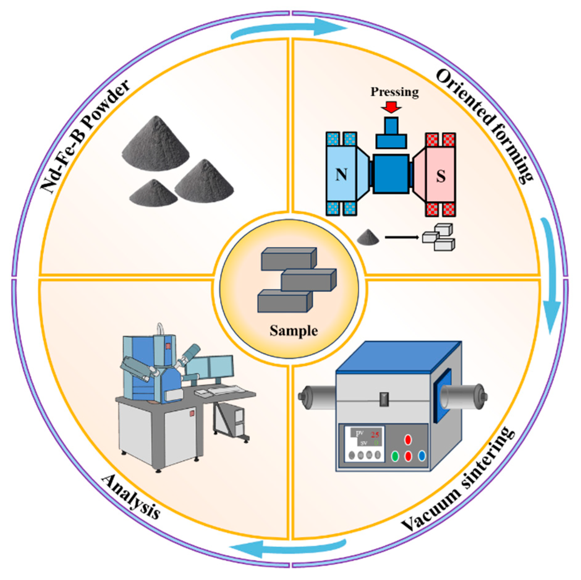
The Nd-Fe-B powder involved in this study was supplied by Jiangxi Yueci Rare Earth New Material Technology Co., Ltd., with a final nominal composition of (Pr,Nd)18.2Ce13Co0.3Cu0.3Zr0.25Ti0.2Al0.1Ga0.1-B0.91Febal. Aimed at clarifying the influence of alignment degree on magnet shrinkage, the research process is illustrated in Figure 1. It started by directionally pressing the magnet powder under aligned magnetic fields of 0 T, 0.75 T, and 1.5 T, and forming the substance into 35 × 35 × 70 mm cuboid green compacts according to the mold. The 70 mm direction represents the magnetic alignment direction. Subsequently, isostatic cold pressing was performed for 10 min at 120 MPa using hydraulic oil as the medium. The green compacts were placed in a furnace for a six-hour vacuum sintering at 1045 °C, followed by primary tempering (780 °C × 3 h) and secondary tempering (640 °C × 6 h), so that the sintered magnets can be garnered. It should be noted that the purpose of this study lies in the influence of alignment degree on the densification behavior of sintered Nd-Fe-B, so other factors that may trim down the alignment degree during preparation are ignored in this paper.
The dimensions of the sintered and heat-treated magnets were measured through a vernier caliper, and their shrinkage rates were computed. The density of each magnet was identified as per the principle of density measurement by the Archimedean drainage method. An X-ray diffractometer (XRD Bruker (Karlsruhe, Germany) D8 ADVANCE) was leveraged to analyze the phase composition and orientation characteristics of the magnets (Step length: 0.02°/min), while the grain size was gauged using electron backscatter diffraction (EBSD Nordlys-Max3 (Oxford Instruments, Abingdon, UK)), and the orientation relationship was further characterized. Relying on a scanning electron microscope (SEM MIRA3-LMH (TESCAN, Brno, Czech Republic)), the microstructures of the three surfaces of the magnet were observed.

3. Results and Discussion

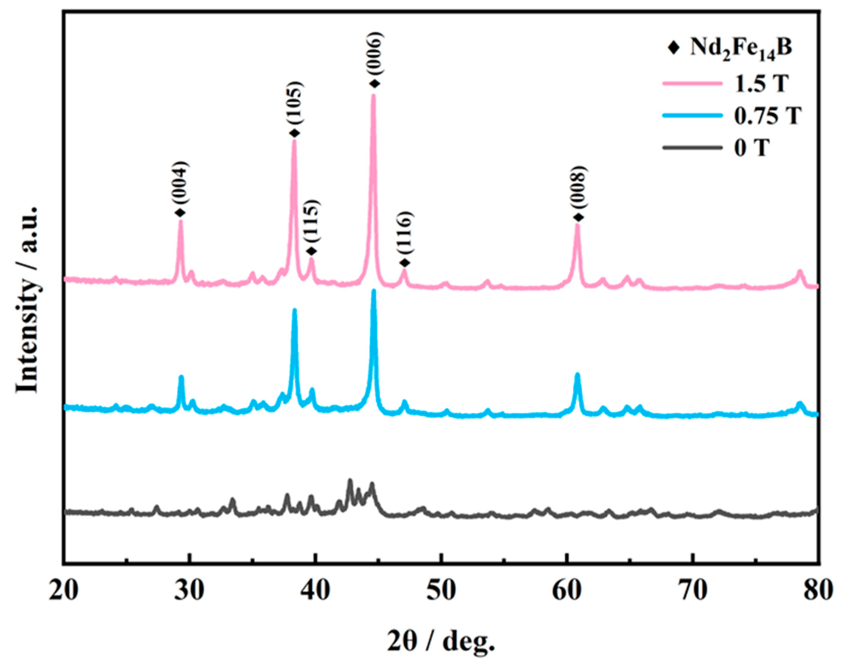
Figure 2 plots the X-ray diffraction patterns of each sample under magnetic field intensities of 0 T, 0.75 T, and 1.5 T. For a magnetic field intensity of 0 T, the intensity is weak for the diffraction peaks in the pattern, with no explicit characteristic peaks. This implies that the main phase grains of the magnet are randomly oriented, exhibiting isotropic characteristics. When the magnetic field intensity is elevated to 0.75 T, the partial diffraction peaks of the magnet are enhanced, and an orientation texture appears, suggesting that some grains inside the magnet are oriented along the direction of the aligned magnetic field. In case of a magnetic field intensity rising to 1.5 T, the intensities of the main diffraction peaks corresponding to the (004), (105), (006), and (008) crystal planes are further reinforced, arousing a highly ordered orientation texture, with pronounced anisotropic characteristics [16,17]. This ascertains that, with the growth of the magnetic field intensity, the alignment degree of the main phase grains of the magnet is improved, and the magnet transforms from isotropic to anisotropic.
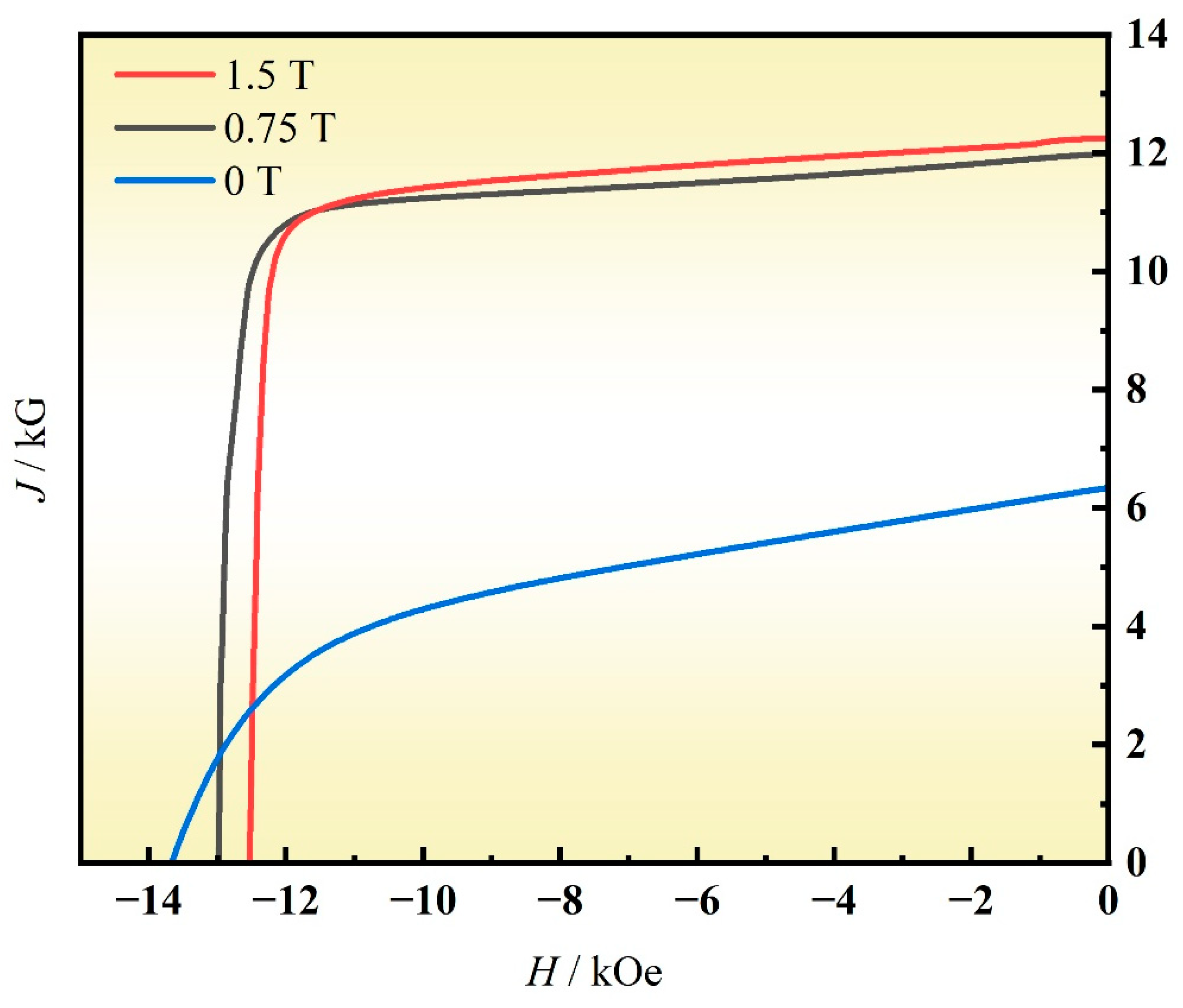
Figure 3 presents the magnetic properties of each magnet under different orientation magnetic field intensities, with specific values listed in Table 1. As the orientation magnetic field intensity increases, the remanence (Br) of the magnets gradually rises: in the absence of a magnetic field, the remanence is only 6.34 kGs; when the magnetic field intensity increases to 0.75 T, the remanence increases to 11.99 kGs; with a further increase in the magnetic field intensity, the remanence of the magnet enhances to 12.25 kGs. However, the coercivity (Hcj) of the magnets decreases slightly [18], falling from 13.67 kOe to 12.54 kOe.
The maximum energy product (BH)max represents the magnetic energy density per unit volume. As the orientation magnetic field intensity increases, the value of (BH)max rises from 8.49 to 34.88 MGOe. Hk/Hcj denotes the squareness (Q) of the magnet: a qualified magnet should have a squareness greater than 90%, and a higher squareness indicates better stability of the magnet. The squareness of the unoriented magnet is only 25.1%, while that of the magnet after orientation treatment exceeds 92%.
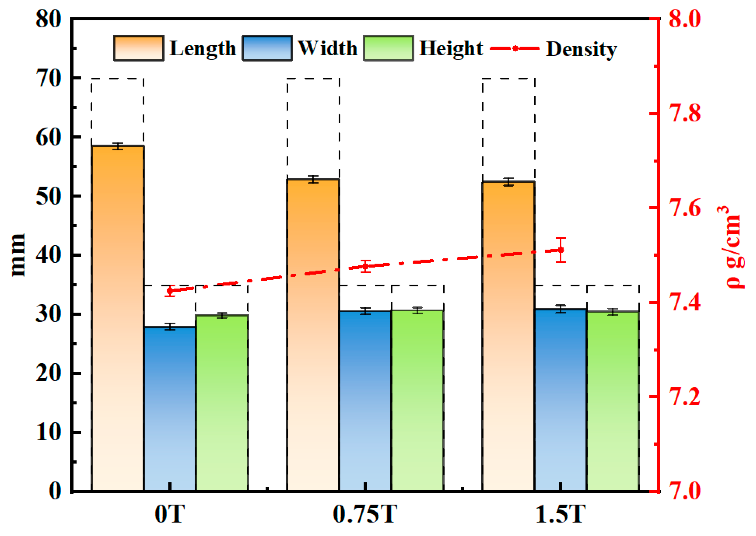
For the sake of analyzing and comparing the influence of alignment degree on the sintering shrinkage of magnets, the dimensions of each magnet after sintering were precisely measured through a vernier caliper, and the results are depicted in Figure 4. The dashed line range in the figure represents the size of the green compact, all of which are 35 × 35 × 70 mm. After sintering, the average dimensions of the magnet prepared under 0 T (no magnetic field) are 28 × 30 × 59 mm, with a shrinkage rate of 16% in the length direction, 20% in the width direction, and 15% in the height direction, exhibiting isotropic shrinkage characteristics. When the magnetic field strength is increased to 0.75 T, the dimensions of the sintered magnet become 31 × 31 × 53 mm, and its shrinkage behavior changes significantly: the shrinkage rate in the length direction (c-axis) reaches 24%, while the shrinkage rate in the width direction is 12% and that in the height direction is 15%. When the magnetic field strength is further increased to 1.5 T, the dimensions of the sintered magnet are 31 × 31 × 52 mm. Compared with the magnet prepared under 0.75 T, there is little difference in overall dimensions; however, the shrinkage rate in the length direction increases further. The shrinkage rate in the length direction is much higher than that in the other two directions, showing obvious anisotropic shrinkage. Such a phenomenon is consistent with the research in reference Cui, X.G. et al. [18], where the shrinkage rate along the magnetic field direction is greater during sintering. The red dashed line in the figure shows how the density of each magnet varies. Notably, the density of the magnet increased from 7.42 ρ g/cm3 to 7.512 ρ g/cm3, displaying a clear upward trend. It can be concluded that enhancing the alignment degree exerts a significant impact on anisotropic shrinkage, resulting in differences in shrinkage rates along various directions, and it can also increase the density to a certain extent.
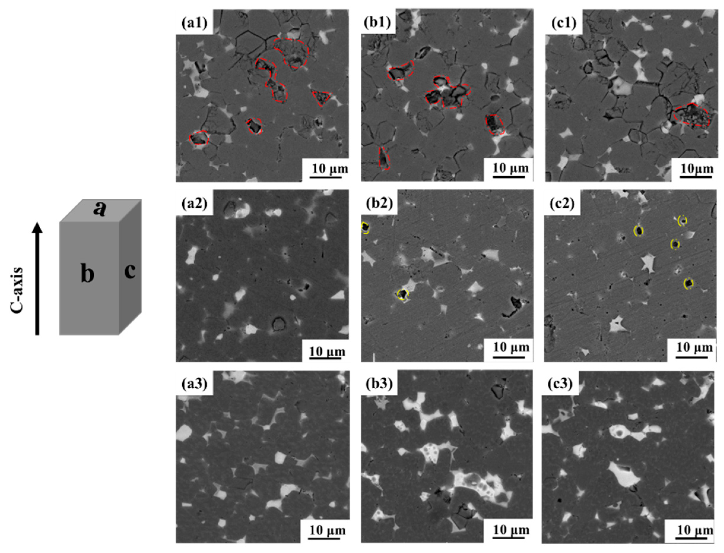
To investigate the phenomenon of inconsistent shrinkage in different directions of magnets after compaction and alignment treatment under different magnetic field strengths, this study employed a scanning electron microscope (SEM) to observe the microstructures of the three surfaces of the magnets. Figure 4 shows the micromorphologies of the three surfaces of the magnets at orientation magnetic field intensities of 0 T, 0.75 T, and 1.5 T, respectively, where the black regions correspond to the main phase of the magnets and the white regions represent the neodymium-rich phases. Figure 5(a1–c1) depicts the microstructures of the three surfaces of the magnet prepared under 0 T. It can be observed that the micromorphologies of the three surfaces are similar, with numerous cracks and pores (red dashed line), indicating a low densification degree [19,20,21].
When the magnetic field strength is increased to 0.75 T, the microstructure of the magnet undergoes significant changes, as shown in Figure 5(a2–c2) (0.75 T): the number of pores is significantly reduced, but some unclosed circular pores (yellow dashed line) still remain. When the orientation magnetic field strength is further increased to 1.5 T, the neodymium-rich phases on the a-plane of the magnet are distributed more uniformly, while those on the other two planes are enriched at the triangular grain boundaries. This is consistent with the research findings of Niu et al. [22]: the main phase grains shrink perpendicular to the orientation direction, and the distribution of Nd-rich grain boundary phases exhibits anisotropy; that is, they are uniformly distributed along the orientation direction (c-axis) with clear and continuous grain boundaries, whereas the neodymium-rich phases in the non-orientation direction are enriched at the triangular grain boundaries.
It can be observed from the micromorphology of the magnets that the unoriented magnet (0 T) has similar micromorphologies in different directions, and grain growth exhibits isotropic characteristics. In contrast, the magnets subjected to magnetic field alignment treatment show significant differences in microstructure among different surfaces: more neodymium-rich phases are distributed at the grain boundaries perpendicular to the c-axis direction [23], and grain growth presents anisotropic characteristics. This is because before sintering, the distribution amount of neodymium-rich phases in the green compact on the plane perpendicular to the c-axis is much higher than that in the other two directions; this phenomenon has not been improved after sintering, resulting in a relatively large number of neodymium-rich phases remaining on the plane perpendicular to the orientation axis of the magnet after sintering [24]. Additionally, the gradual reduction in small particles with low densification can also prove that the density of the magnet increases to a certain extent as the degree of alignment improves.
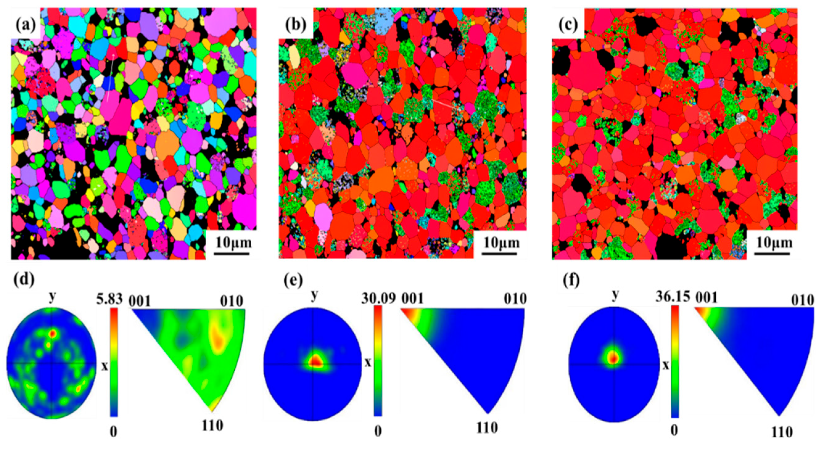
With the intent of further analyzing the effect of different aligned magnetic field intensities on the alignment degree, the orientation of each magnet was analyzed via EBSD. Figure 6a portrays the IPF pattern of the 0 T magnet. The different colors of the main phase grains in the figure designate a disordered arrangement of c-axis directions. The maximum of the (001) texture concentration in the pole figure is 5.83. For the 0.75 T magnet, the color of the main phase grains turns to red, approaching the (001) texture, and the maximum of the texture concentration in the pole figure is 30.09. The color of the 1.5 T magnet is closer to the (001) texture, and the maximum of the texture concentration in its pole figure increases to 36.15. This also evidences that, with the growth of the aligned magnetic field intensity, the alignment degree progressively enlarges [6].
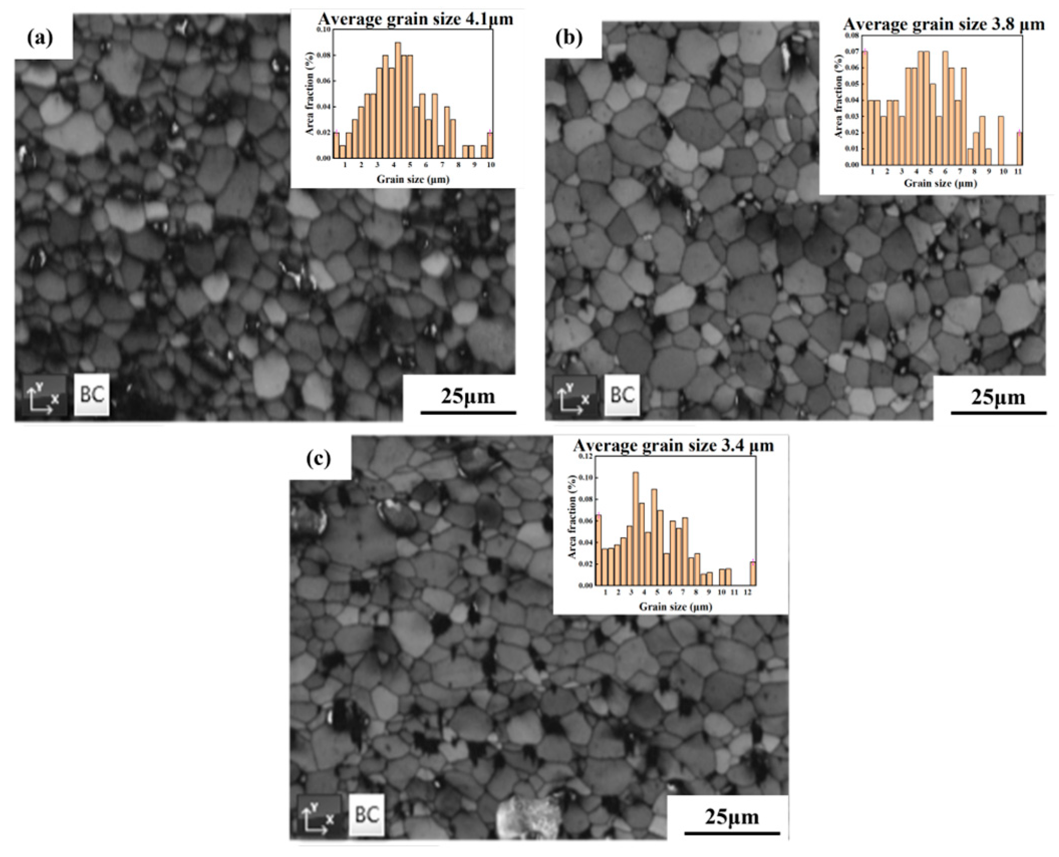
Figure 7 depicts the grain size distribution of the main phase in magnets with different degrees of alignment. The magnet prepared at 0 T exhibits an average grain size of 4.1 μm, with a wide variation in grain size that is mainly distributed in the range of 3.5–5 μm. For the magnet fabricated at 0.75 T, the average grain size is 3.8 μm, characterized by a reduction in large-sized grains and an increase in the proportion of grains within the range of 0–3 μm. The average grain size of the magnet processed at 1.5 T decreases to 3.4 μm, and its grain size is predominantly distributed around 3 μm. This corroborates that the grain size can be reduced by a higher degree of alignment—ascribed to the fact that with a rising alignment degree, the easy magnetization axes of the grains are arranged in the direction of the applied magnetic field [22,24]. The deviation of the arrangement of magnet powders tapers off, forming numerous grain boundaries with small orientation deviations. The growth behavior of grains is affected by the misorientation of grain boundaries. The grain boundaries with small orientation deviations possess lower mobility [6] which achieves grain refinement by thwarting the movement of grain boundaries and grain growth.
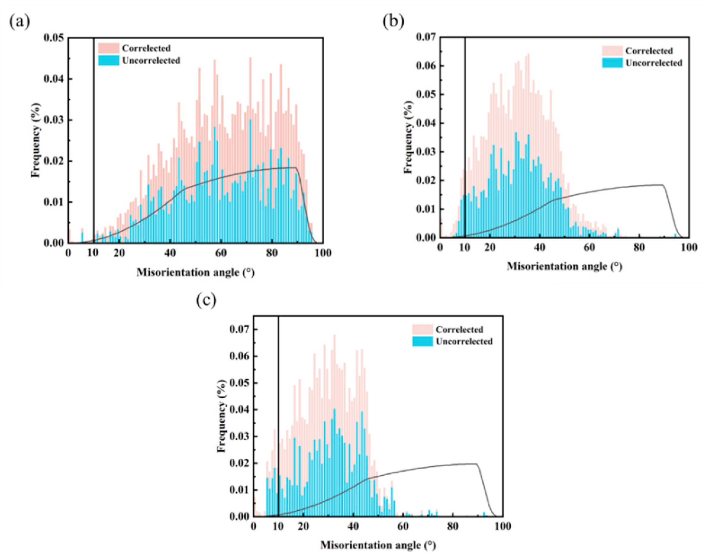
The distribution frequency of adjacent and non-adjacent grain boundaries in magnets with different degrees of alignment was statistically analyzed via electron backscatter diffraction (EBSD), as illustrated in Figure 8. The black curve in the figure represents the theoretical reference line for the random arrangement of grains. The pink area is defined as the misorientation angle adjacent pairs of grain boundaries, corresponding to the distribution frequency of crystal misorientation angles between adjacent grains near the grain boundaries [25,26]. The frequency of adjacent pairs distributed in the range of 0–10° indicates the quantity of low-angle grain boundaries; the higher the frequency, the greater the quantity of low-angle grain boundaries. The blue area is defined as random pairs, representing the distribution frequency of crystal misorientation angles between non-adjacent grains near the grain boundaries; the closer the distribution of random pairs is to the theoretical value, the lower the texture degree [27]. Figure 8a presents the misorientation angle distribution of the magnet prepared at 0 T. The coincidence degree between the distributions of adjacent and non-adjacent grain boundaries reaches 99%, indicating that the 0 T magnet has a low degree of alignment, fails to form a texture, and contains an extremely small number of low-angle grain boundaries. Figure 7b illustrates the misorientation angle distribution of the magnet fabricated under a magnetic field intensity of 0.75 T, where the random pairs deviate significantly from the theoretical curve, with the coincidence degree decreasing to 41%. When the magnetic field intensity is increased to 1.5 T, the coincidence degree between the distributions of adjacent and non-adjacent grain boundaries drops to 34%, accompanied by a further increase in the quantity of low-angle grain boundaries.
These results demonstrate that with the increase in the alignment magnetic field intensity, the texture degree is significantly improved, the arrangement of magnet grains becomes more ordered, and more low-angle grain boundaries are formed. The variation in the proportion of low-angle grain boundaries suggests that as the alignment magnetic field intensity rises, the differences between magnet grains become increasingly small, the main-phase grains tend to be consistent, and the anisotropy characteristics become more pronounced.
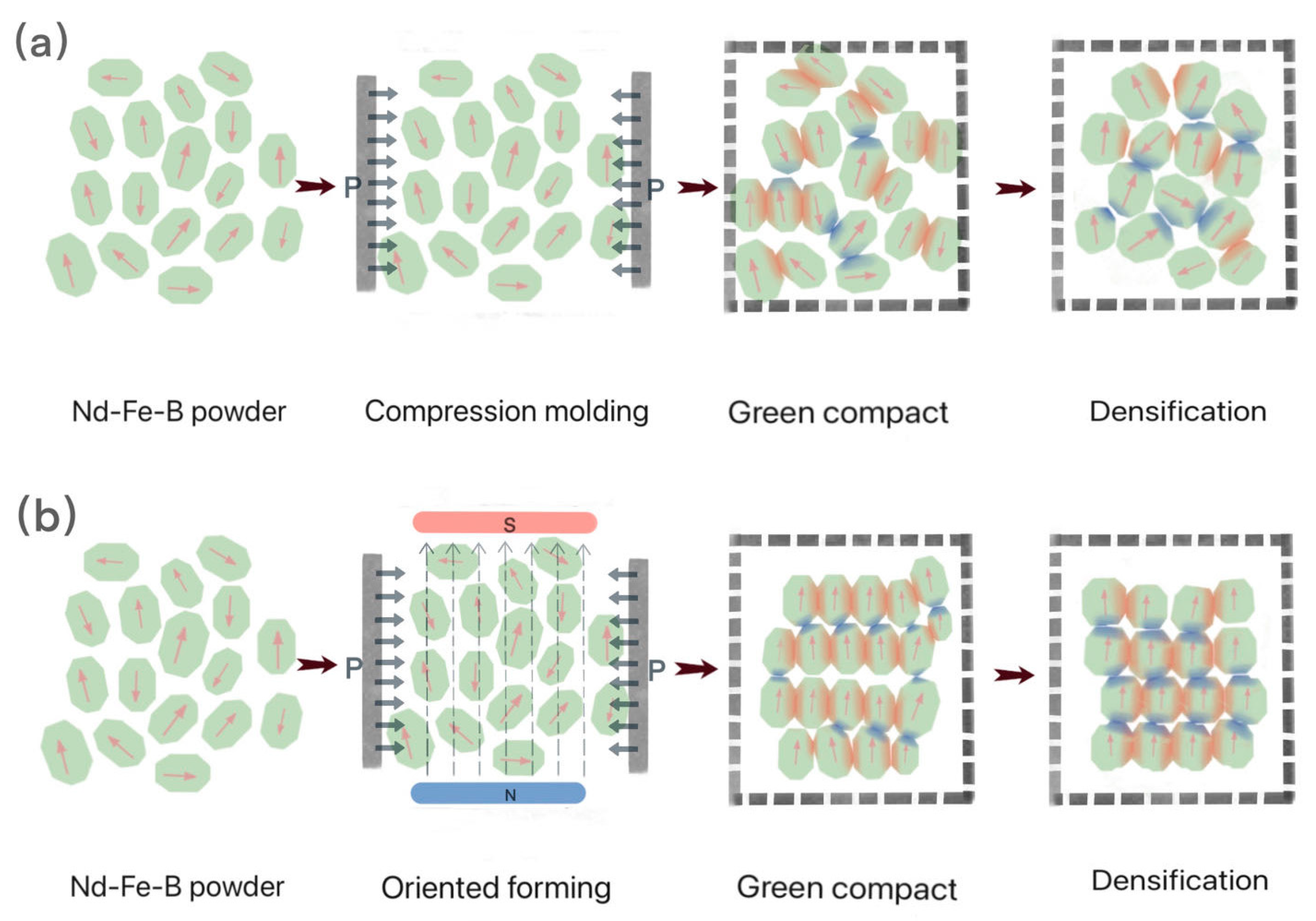
To more intuitively illustrate the content presented in this paper, Figure 9 shows a schematic diagram of the preparation and densification processes of magnets with different degrees of alignment. Figure 9a represents the preparation and densification process of the magnet without alignment treatment: the magnet powder is directly subjected to compaction, and the c-axes of the Nd2Fe14B phase in the green compact are randomly arranged. During densification, multiple small grains gradually grow into a single large grain, and pores are gradually eliminated to complete the densification process. Since no alignment treatment is applied, the main-phase grains of the magnet do not form a texture, and the growth rates in all directions are similar. Therefore, its shrinkage behavior exhibits isotropy. Figure 9b depicts the preparation and densification process of the magnet after alignment treatment. An alignment magnetic field is applied during the compaction process, causing the main-phase grains of the magnet to align along the direction of the alignment magnetic field, thus forming obvious texture characteristics. Studies have confirmed that during the sintering process, the Nd2Fe14B phase preferentially grows along the a-axis [22]. Consequently, the misorientation angle in the a-axis direction is larger, and high-angle grain boundaries (marked as red regions in the figure) are preferentially formed during sintering. In contrast, the growth rate in the c-axis direction is slower, the misorientation angle is smaller, and mainly low-angle grain boundaries (marked as blue regions in the figure) are formed. Because different contact orientations affect the anisotropic surface energy and mobility, varying neck growth and densification rates are spawned [15]. The grain boundary energy of high-angle grain boundaries is higher than that of low-angle grain boundaries, and grain boundary migration is faster, so necking occurs preferentially during sintering. Schwen et al. [27] demonstrated that the formation rate of necking increases with the increase in misorientation angle, while the necking length decreases as the misorientation angle increases. Ascribed to the regular arrangement of grains in the oriented magnet, more low-angle grain boundaries are formed during sintering, allowing the liquid phase to flow more easily along the grain boundary channels. Moreover, the microstructure of the grain boundary phase in the c-axis direction is optimized better than that in other directions [18].

4. Conclusions

This study investigated the macroscopic shrinkage behavior of sintered Nd-Fe-B samples under different alignment magnetic field strengths. Magnets with different degrees of alignment were prepared by adjusting the strength of the alignment magnetic field. By analyzing the influence of different alignment degrees on the macroscopic dimensions and micromorphology of the magnets, the effect of alignment degree on the densification behavior of the magnets was explored. The specific conclusions are as follows:
For the unoriented magnet, the a-axes and c-axes of the grains are randomly distributed, with large misorientation angles in all directions, and there is no significant difference in the growth rate among different directions. Therefore, the shrinkage exhibits isotropic characteristics. After magnetic field alignment, the c-axes of the main-phase grains are oriented along the direction of the magnetic field, resulting in small misorientation angles in the c-axis direction and the formation of low-angle grain boundaries. In contrast, the growth rate in the a-axis direction is faster, mainly forming high-angle grain boundaries. Since both the mobility and grain boundary energy of low-angle grain boundaries are lower than those of high-angle grain boundaries, during the sintering process, high-angle grain boundaries preferentially undergo densification, leading to differences in densification rates. Consequently, the shrinkage of the magnet in the c-axis direction is greater than that in the other two directions, showing anisotropic shrinkage characteristics. In summary, the differences in grain boundary orientation caused by different degrees of alignment are important factors leading to anisotropic shrinkage.

Author Contributions

Y.S. did conceptualisation, methodology, validation, formal analysis, investigation, writing—the original draft, reviving and editing. Y.D. did writing, reviving and editing, resources and founding acquisition. J.Z. and Z.L. performed conceptualisation and methodology. Q.W., W.X., Y.C. and W.N. took part in the investigation. All authors have read and agreed to the published version of the manuscript.

Funding

This study was funded by National Key Research and Development Program (2022YFB3505400); Ganzhou Key Research and Development Program Key Project (2023PGX37042). Jiangxi Provincial Key Laboratory: Jiangxi Key Laboratory of Maglev Rail Transit Equipment (2020SSY050); Jiangxi Provincial Department of Education Science and Technology Research Project (GJJ170501); The cultivation project of the State Key Laboratory of Green Development and High-value Utilization of Ionic Rare Earth Resources in Jiangxi Province (20194AFD44003).

Data Availability Statement

The data that support the findings of this study are available from the corresponding author, Deng, upon reasonable request.

Conflicts of Interest

Author Qingchang Wu was employed by the company Jiangxi Yueci Rare Earth New Material Technology Co., Ltd. The remaining authors declare that the research was conducted in the absence of any commercial or financial relationships that could be construed as a potential conflict of interest.

References

  1. Coey, J. Permanent magnets: Plugging the gap. Scr. Mater. 2012, 67, 524–529. [Google Scholar] [CrossRef]
  2. Sugimoto, S. Current status and recent topics of rare-earth permanent magnets. J. Phys. D Appl. Phys. 2011, 44, 064001. [Google Scholar] [CrossRef]
  3. Titov, I.; Honecker, D.; Mettus, D.; Feoktystov, A.; Kohlbrecher, J.; Strunz, P.; Michels, A. Anisometric mesoscale nuclear and magnetic texture in sintered Nd-Fe-B magnets. Phys. Rev. Mater. 2020, 4, 054419. [Google Scholar] [CrossRef]
  4. Matsuura, Y. Recent Development of Nd-Fe-B Sintered Magnets and Their Applications. ChemInform 2006, 37, 344–347. [Google Scholar] [CrossRef]
  5. Bordia, R.K.; Kang, S.-J.L.; Olevsky, E.A. Current understanding and future research directions at the onset of the next century of sintering science and technology. J. Am. Ceram. Soc. 2017, 100, 2314–2352. [Google Scholar] [CrossRef]
  6. Meng, R.Y.; Xu, J.Y.; Zhang, J.T.; Liu, J.; Fang, Y.K.; Dong, S.Z.; Li, W. Thermal expansion behavior of sintered Nd–Fe–B magnets with different Co contents and orientations. Chin. Phys. B 2023, 32, 573–579. [Google Scholar] [CrossRef]
  7. Dong, S.; Li, X.; Lu, Q.; Liu, W.; Wu, Y.; Yue, M. Study on mechanical properties of recycled sintered Nd-Fe-B magnets. J. Alloys Compd. 2023, 962, 171156. [Google Scholar] [CrossRef]
  8. Bolis, K.; Silva Goulart, G.; Krohling, A.C.; Mendonca, R.; Fernandez-Outon, L.E.; Domingos Ardisson, J. Structural and Magnetic Characterization of Nd–Pr–Fe–B Sintered Magnet Machining Wastes. ACS Omega 2023, 8, 12246–12258. [Google Scholar] [CrossRef]
  9. Han, X.; Lin, L.; TMiyazaki, F.Y.; Xu, R.; Wang, X.; Pan, H.; Chen, C. Hydrogenation and Anisotropic Expansions in R3Fe29-xTx (R=Y, Ce, Nd, Sm, Gd, Tb and Dy; T=V and Cr). Chin. J. Mater. Sci. Technol. 1999, 15, 5. [Google Scholar]
  10. Liu, X.; Hu, L.; Sun, Y.; Li, Y.; Sun, H. Crystallographic alignment and magnetic anisotropy inducement from as-deformed disproportionated Nd(Fe,Co)B alloy with different deformation ratios. J. Alloys Compd. 2016, 668, 137–145. [Google Scholar]
  11. Ni, J.; Luo, W.; Hu, C.; Yin, Y.; Zhang, D.; Peng, X.; Han, Q. Relations of the structure and thermal stability of NdFeB magnet with the magnetic alignment. J. Magn. Magn. Mater. 2018, 468, 105–108. [Google Scholar] [CrossRef]
  12. Liu, Y.C.; Shui, A.Z.; Ren, X.T.; Zeng, L.K. Sintering shrinkage anisotropy of spherical alumina powder compacts with particle orientation. Key Eng. Mater. 2007, 334, 293–296. [Google Scholar] [CrossRef]
  13. Byun, J.M.; Kim, M.S.; Kim, S.H.; Kim, J.W.; Do Kim, Y. A Phenomenological Analysis on the Anisotropic Shrinkage of Nd–Fe–B Compacts During Sintering Process. IEEE Trans. Magn. 2016, 52, 2101404. [Google Scholar]
  14. Hugonnet, B.; Missiaen, J.M.; Martin, C.L.; Rado, C. Effect of contact alignment on shrinkage anisotropy during sintering: Stereological model, discrete element model and experiments on NdFeB compacts. Mater. Des. 2020, 191, 108575. [Google Scholar] [CrossRef]
  15. Ishii, A.; Kondo, K.; Yamamoto, A.; Yamanaka, A. Phase-field modeling of solid-state sintering with interfacial anisotropy. Mater. Today Commun. 2023, 35, 106061. [Google Scholar] [CrossRef]
  16. Yu, Y.; Li, J.; Liu, Y.; Wang, R.; Lian, L. Highly oriented NdFeB nanocrystalline magnets from partially recombined compacts with ultrafine grain size by reactive deformation under low pressure. J. Rare Earths 2015, 33, 1298–1302. [Google Scholar] [CrossRef]
  17. Endoh, M.; Shindo, M. Material Design and Development of High Performance Nd-Fe-B Sintered Magnets. J. Jpn. Soc. Powder Powder Metall. 1994, 41, 985–988. [Google Scholar] [CrossRef]
  18. Cui, X.G.; Cui, C.Y.; Cheng, X.N.; Xu, X.J.; Ma, T.Y.; Yan, M.; Wang, C. Effects of alignment on the magnetic and mechanical properties of sintered Nd–Fe–B magnets. J. Alloys Compd. 2013, 563, 161–164. [Google Scholar] [CrossRef]
  19. Luo, S.; Gao, X.; Yang, M.; Zhong, S.; Yu, X.; Rehman, S.U.; Li, C.; Li, L.; Zhang, W.; Bulyk, I.I.; et al. Effect of texture intensity on grain boundary diffusion in sintered NdFeB magnets. J. Mater. Res. Technol. 2025, 35, 4734–4744. [Google Scholar] [CrossRef]
  20. Ozer, I.O.; Suvaci, E.; Karademir, B.; Missiaen, J.M.; Carry, C.P.; Bouvard, D. Anisotropic Sintering Shrinkage in Alumina Ceramics Containing Oriented Platelets. J. Am. Ceram. Soc. 2006, 89, 1972–1976. [Google Scholar] [CrossRef]
  21. Niu, E.; Chen, Z.-A.; Ye, X.-Z.; Zhu, W.; Chen, G.-A.; Zhao, Y.-G.; Zhang, J.; Rao, X.-L.; Hu, B.-P.; Wang, Z.-X. Anisotropy of grain boundary diffusion in sintered Nd-Fe-B magnet. Appl. Phys. Lett. 2014, 104, 262405. [Google Scholar] [CrossRef]
  22. Li, A.; Dong, S.; Li, W. Anisotropy of mechanical properties and fracture behaviour in sintered NdFeB permanent magnetic materials. RARE Met. Mater. Eng. 2003, 32, 631–634. [Google Scholar]
  23. Gao, R.W.; Zhang, D.H.; Li, H.; Zhang, J.C. Effects of the degree of grain alignment on the hard magnetic properties of sintered NdFeB magnets. Appl. Phys. A—Mater. Sci. Process. 1998, 67, 353–356. [Google Scholar] [CrossRef]
  24. Zueco, E.; Rave, W.; Schäfer, R.; Hubert, A.; Schultz, L. Combined Kerr-/magnetic force microscopy on NdFeB crystals of different crystallographic orientation. J. Magn. Magn. Mater. 1998, 190, 42–47. [Google Scholar] [CrossRef]
  25. Gao, X.; Zheng, F.; Zhong, S.; Yang, M.; Wang, H.; Li, L.; Li, C.; Luo, S.; Bulyk, I.; Li, J.; et al. Optimization of comprehensive magnetic properties of sintered Nd-Fe-B magnet via novel magnetic field orientation forming technology. J. Alloys Compd. 2025, 1031, 181078. [Google Scholar] [CrossRef]
  26. Zhong, S.; Yang, M.; Rehman, S.U.; Luo, S.; Li, L.; Li, C.; Li, J.; Ma, Q.; Xiong, S.; Bulyk, I.; et al. Mechanical property enhancement of sintered Nd-Fe-B magnets by dual-scale regulation of microstructure. Intermetallics 2023, 152, 107772. [Google Scholar] [CrossRef]
  27. Biswas, S.; Schwen, D.; Wang, H.; Okuniewski, M.; Tomar, V. Phase field modeling of sintering: Role of grain orientation and anisotropic properties. Comput. Mater. Sci. 2018, 148, 307–331. [Google Scholar] [CrossRef]
Figure 1. Flow chart of magnet preparation process.
Magnetism 06 00012 g001
Figure 2. XRD patterns of magnets under different aligned magnetic field intensities.
Magnetism 06 00012 g002
Figure 3. Demagnetization curves of the magnets prepared under different alignment magnetic fields.
Magnetism 06 00012 g003
Figure 4. Magnet dimensions (before sintering: black dashed line; after sintering: solid line) and post-sintering density: red dashed line.
Magnetism 06 00012 g004
Figure 5. SEM images of different surfaces of magnets with different oriented magnetic fields: 0 T (a1c1); 0.75 T (a2c2); 1.5 T (a3c3).
Magnetism 06 00012 g005
Figure 6. EBSD maps: (a) 0 T, (b) 0.75 T, (c) 1.5 Tand corresponding pole figures: (d) 0 T, (e) 0.75 T, (f) 1.5 T of magnets under different aligned magnetic field intensities.
Magnetism 06 00012 g006
Figure 7. Grain size distribution of magnets with different alignment degrees: (a) 0 T, (b) 0.75 T, (c) 1.5 T.
Magnetism 06 00012 g007
Figure 8. Distribution Frequency of Adjacent and Non-adjacent Grain Boundaries in Magnets at 0 T (a), 0.75 T (b) and 1.5 T (c).
Magnetism 06 00012 g008
Figure 9. Schematic diagram of preparation and densification processes for magnets with different alignment degrees: (a) non-oriented, (b) fully oriented.
Magnetism 06 00012 g009
Table 1. Magnetic Properties of Magnets Under Different Alignment Magnetic Field Strengths.
SampleBr
kGs
Hcj
kOe
(BH)max
MGOe
Hk/Hcj
(%)
0 T6.3413.678.4925.1
0.75 T11.9912.9933.1692.5
1.5 T12.2512.5434.8892.2
Disclaimer/Publisher’s Note: The statements, opinions and data contained in all publications are solely those of the individual author(s) and contributor(s) and not of MDPI and/or the editor(s). MDPI and/or the editor(s) disclaim responsibility for any injury to people or property resulting from any ideas, methods, instructions or products referred to in the content.