
Article

Parametric Optimization of a Spoke-Type Double-Stator and Single-Rotor Axial Flux Permanent Magnet Motor
1
Department of Electrical Engineering, The University of Larkano, Larkana 77150, Pakistan
2
Institute of Electrical Drives and Machines, University of Erlangen-Nuremberg, 91058 Erlangen, Germany
*
Author to whom correspondence should be addressed.
Magnetism 2026, 6(1), 11; https://doi.org/10.3390/magnetism6010011
Submission received: 26 September 2025 / Revised: 13 February 2026 / Accepted: 28 February 2026 / Published: 3 March 2026

Abstract

This paper presents a detailed parametric optimization of a spoke-type double stator and single-rotor (DSSR)-type axial flux permanent magnet (AFPM) motor based on the design of experiment (DoE) method coupled with 3D finite element analysis (FEA). Design variables are selected, and their individual effects on the output characteristics of the spoke-type DSSR AFPM motor are analyzed. The interactive effects of the design variable pairs are also investigated to understand their mutual influence on the spoke-type DSSR AFPM motor’s output characteristics. For the optimal design of the spoke-type DSSR AFPM motor, different values of each design variable are determined using Latin Hypercube Sampling (LHS) and analyzed using the 3D FEA method.

1. Introduction

Slotted double-stator and single-rotor (DSSR)-type axial flux permanent magnet (AFPM) machines have more power and torque density and a lower cost and fewer cooling issues compared to single-stator and double-rotor (SSDR)-type AFPM machine structures [1,2]. Spoke-type DSSR AFPM machines consume fewer the permanent magnets (PMs) and have a higher torque density compared to surface-mounted permanent magnet (SPM)-type DSSR AFPM machines [3,4].
Latin Hypercube Sampling (LHS) is a statistical space-filling technique in the design of experiment (DoE) method that is used for optimization [5]. LHS divides each design variable’s range into intervals, ensuring uniform coverage with fewer samples rather than full-factorial samples of 2 n , where n is the number of the design variables [6,7]. Although the one-factor-at-time (OFAT) method is a simple approach, it often misses the critical interactive influence of the design variables, whereas the full-factorial method is extremely computationally expensive [7,8]. Thus, the DoE method is computationally efficient and well adapted for the investigation of the effects of different variations in design parameters on a given device [9]. The DoE method is simple and does not essentially require sophisticated algorithms and programing aside from the FEA [10]. Therefore, the DoE method is utilized for the parametric optimization of a spoke-type DSSR AFPM motor using 3D FEA in this study.
In this research article, the basic features of a spoke-type DSSR AFPM motor and the DoE method for parametric optimization are provided in Section 1. Section 2 deals with the basic model of the spoke-type DSSR AFPM motor and its characteristic analysis. Section 3 deals with the methodology of the parametric optimization, and the main, mutual and collective influences of the design variables are investigated using 3D FEA. An optimal model of the spoke-type DSSR AFPM motor is selected, and its comparative analysis with the basic model is carried out in Section 4. Lastly, the presented research work is concluded in Section 5.

2. Spoke-Type DSSR AFPM Motor

In a spoke-type DSSR AFPM motor, the PMs are inserted in the solid rotor core, and the rotor is sandwiched between two identical stators, as shown in the Figure 1. Double-layer tooth coil windings are wound on each stator tooth to shorten the end winding length.

2.1. Basic Model

The geometrical specifications of the basic model of the spoke-type DSSR AFPM motor shown in Figure 1 are given in Table 1. It has 36 winding slots in each stator and 24 rotor poles. The analytically determined optimal ratio between the inner and outer radii of the spoke-type DSSR AFPM motor is 1 / 3 [11]. Therefore, the inner stator as well as the rotor radius of the basic model of the spoke-type DSSR AFPM motor is 52 mm.
Unlike conventional spoke-type radial flux permanent magnet (RFPM) motors, the rotor, including the PMs of the spoke-type DSSR AFPM motor, is equally attracted towards both stators; therefore, the PM bridges or the ribs facing the airgap are not essential, which generally reduces the electromagnetic performance of spoke-type RFPMs [2,12]. Although the DSSR AFPM motor’s rotor is ideally balanced, still it needs strong mechanical support to avoid deflection towards the stator.

2.2. Output Characteristics of the Basic Model

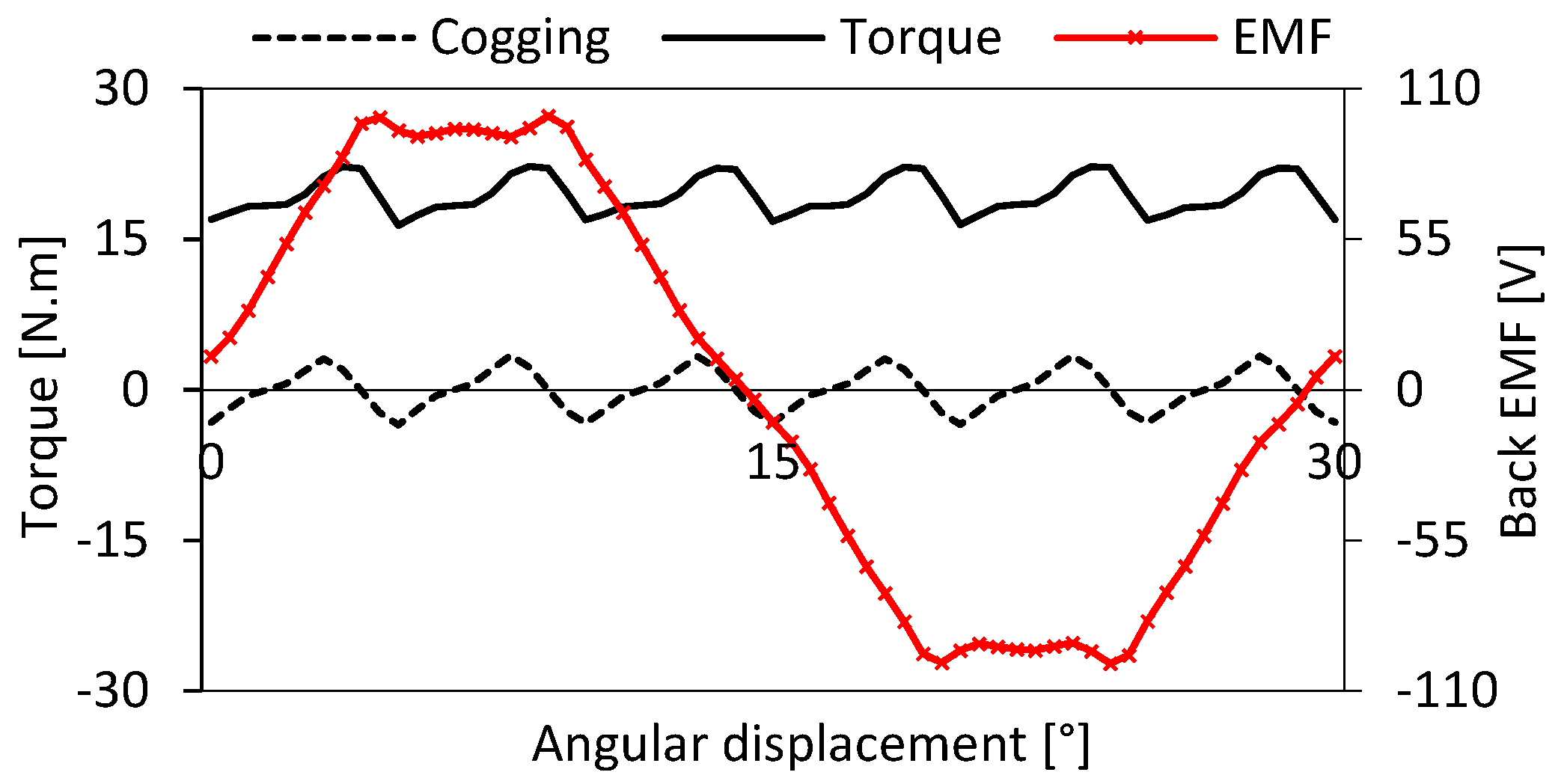
Figure 2 shows the simulated output characteristics of the basic model of the spoke-type DSSR AFPM motor. It has natural cooling; therefore, the considered current density is 4 A/mm2, and the supplied per-phase current is 7.07 A. The basic model of the spoke-type DSSR AFPM motor has a back EMF of 72 V, an electromagnetic torque of 19.37 N·m and peak-to-peak torque ripples and a cogging torque of 5.91 N·m and 6.92 N·m, respectively.

3. Parameter Analysis and Optimization

The DoE is a systematic and efficient approach used for the detailed parametric analysis of the spoke-type DSSR AFPM motor using a 3D FEA simulation by Altair® Flux® 2019 version.

3.1. Design Variables

The outer radius of the stator and the rotor, the airgap length, and the rotor and stator axial lengths are all kept constant. The supplied current and the current density are also constant; however, the number of turns in the stator coils varies according to the space provided by the stator slot.
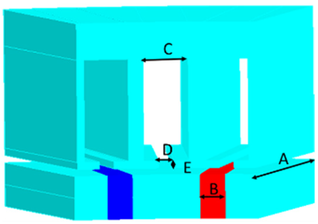
The design variables of the spoke-type DSSR AFPM motor are presented in Figure 3, and their ranges of variation are given in Table 2. The basic model of the spoke-type DSSR AFPM motor has a PM length and width of 36.5 mm and 4 mm, respectively, whereas it has a stator slot width, slot opening width and tooth tip height of 7.5 mm, 2.5 mm and 1 mm respectively. Thus, by using the reference values of the basic model’s variables as the mean values, the lower and upper bounds of each design variable in Table 2 are equally ranged for the electromagnetic parametric optimization. With the same lower and upper bounds, the influence of the design variables on the electromagnetic characteristics of the spoke-type DSSR AFPM motor is facile and rationally comparable. Variation in the PM length and stator inner radius also varies the ratio between the inner and outer radius of the rotor as well as the stator. The stator slot is rectangular, and its variation affects the stator tooth width. Therefore, a bigger stator slot width increases the space for the stator coil windings; however, a reduced stator teeth width will adversely affect the magnetic flux saturation in the stator teeth. The PM length as well as its width influences the airgap magnetic flux density. Therefore, the influence of the variation in the design variables is realized and investigated for the electromagnetically optimized model of the spoke-type DSSR AFPM motor.

3.2. Main Effect of Each Design Variable

The OFAT method is adopted to investigate the influence of the design variables on the electromagnetic characteristics of the spoke-type DSSR AFPM motor. The minimum (A1, B1, C1, D1, E1 and F1) and maximum (A3, B3, C3, D3, E3 and F3) values of each design variables are 35, 3, 6, 1, 0, and 50 and 38, 5, 9, 4, 2, and 54, respectively, and their effect on the output characteristics of the spoke-type DSSR AFPM motor are analyzed using 3D FEA. In addition, the basic model of the spoke-type DSSR AFPM motor has a mean value of 36.5, 4, 7.5, 2.5, 1 and 52 for each design variable A2, B2, C2, D2, E2 and F2, respectively. Due to the two extreme values of each design variable, the simulation time is reduced, and the deviation in the characteristics from the basic model of the spoke-type DSSR AFPM motor becomes evident. The numerical suffixes of 1, 2 and 3 for each design variable’s symbol represent the minimum, mean and maximum values, respectively.
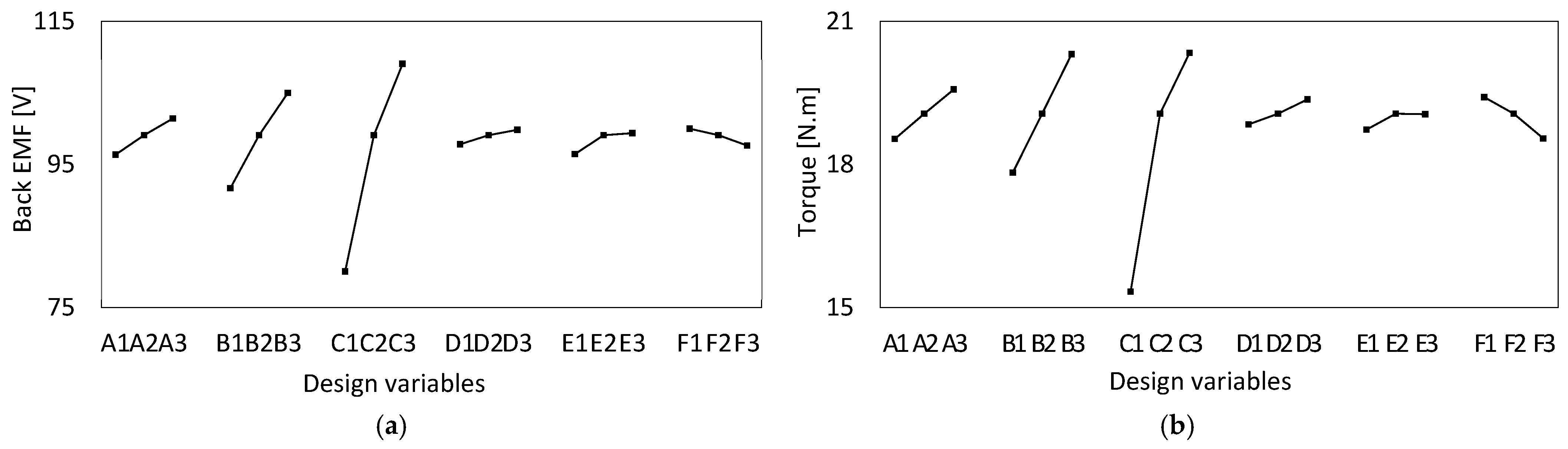
Figure 4a represents the main effect of each individual design variable on the back EMF of the spoke-type DSSR AFPM motor. The slot width C has a significant effect on the back EMF because as the slot width increases, the number of turns increases and so does the back EMF. A decrease in the slot width highly decreases the back EMF, and as such, the C2 to C1 effect is more adverse than C3 to C2. Similarly, obliging the Faraday equation when the PM length A and the PM width B increase, the back EMF also increases; however, the PM width has more of an effect than the PM length. An increased PM length of the spoke-type DSSR AFPM motor results in more flux leakages due to the lesser inner radius of the rotor as compared to the inner radius of the stator.
The slot opening width D has a slight effect on the back EMF, and as the slot opening increases, the back EMF also increases due to the fewer flux leakages between the stator tooth tips. A spoke-type DSSR AFPM motor with no tooth tip E1 and a full slot opening has less back EMF because the tooth tips improve the magnetic flux linkages. As the sum of the tooth tip height and slot height is kept constant, a suitable tooth tip height should be selected, because high tooth tips reduce the space for the stator winding as well. The back EMF reduces when the stator inner radius F increases because an active winding length reduces the flux linkages, and the inner-to-outer radius ratio of the stator also increases.
Figure 4b presents the main effect of each design variable on the average torque values of the spoke-type DSSR AFPM motor. The variation in each design variable affects the mean electromagnetic torque similarly to that of the back EMF in Figure 4a. Without the tooth tip, the electromagnetic torque as well as the back EMF either increases or decreases with the increase in the design variable value in their predefined range.
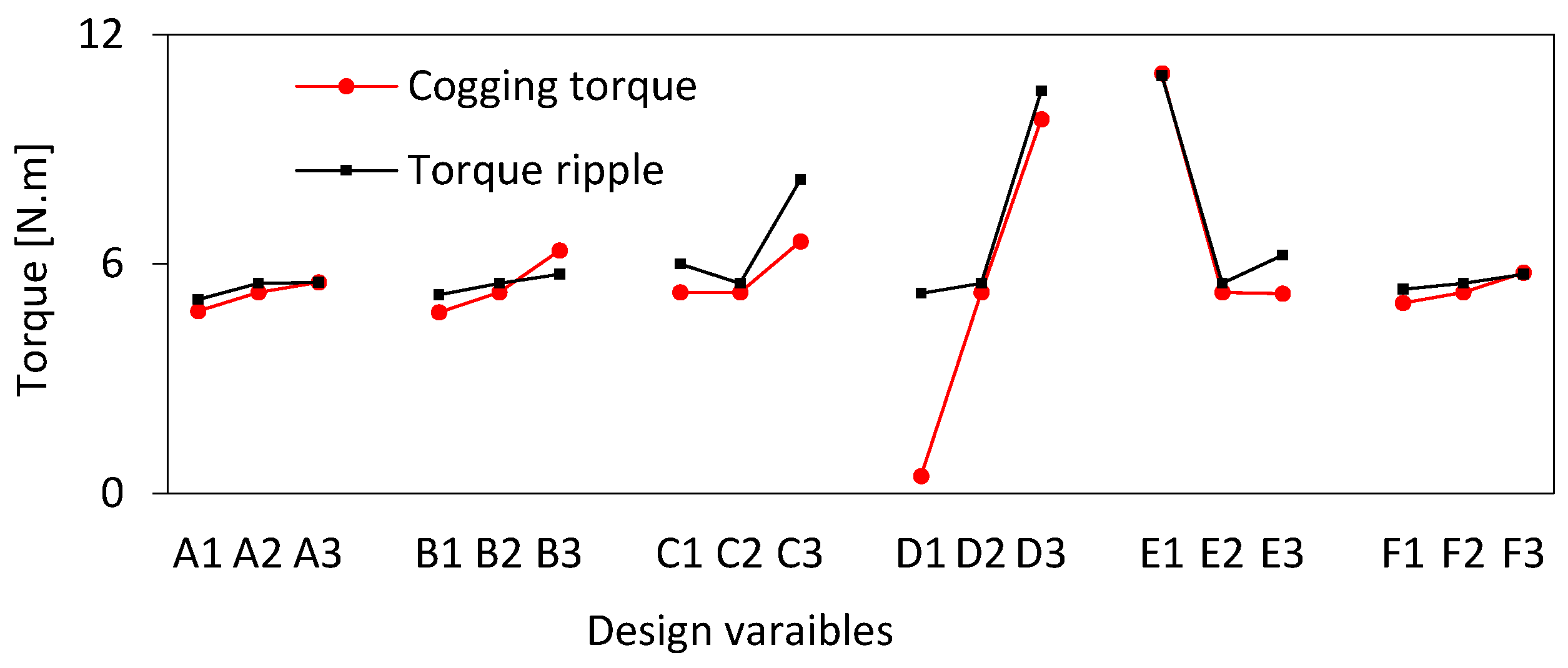
Peak-to-peak values of the cogging torque and torque ripple of the spoke-type DSSR AFPM motor are shown in Figure 5. Without tooth tips, the effective airgap length increases, and the spoke-type DSSR AFPM motor has the minimum cogging torque. The effect of variation in C2-C3, D2-D3 and E2-E1 is more than that of C2-C1, D2-D1 and E2-E3, respectively. When the PM length A, PM width B, and the inner radius of the stator F increase, cogging and torque ripples increase.

3.3. Interactive Effect

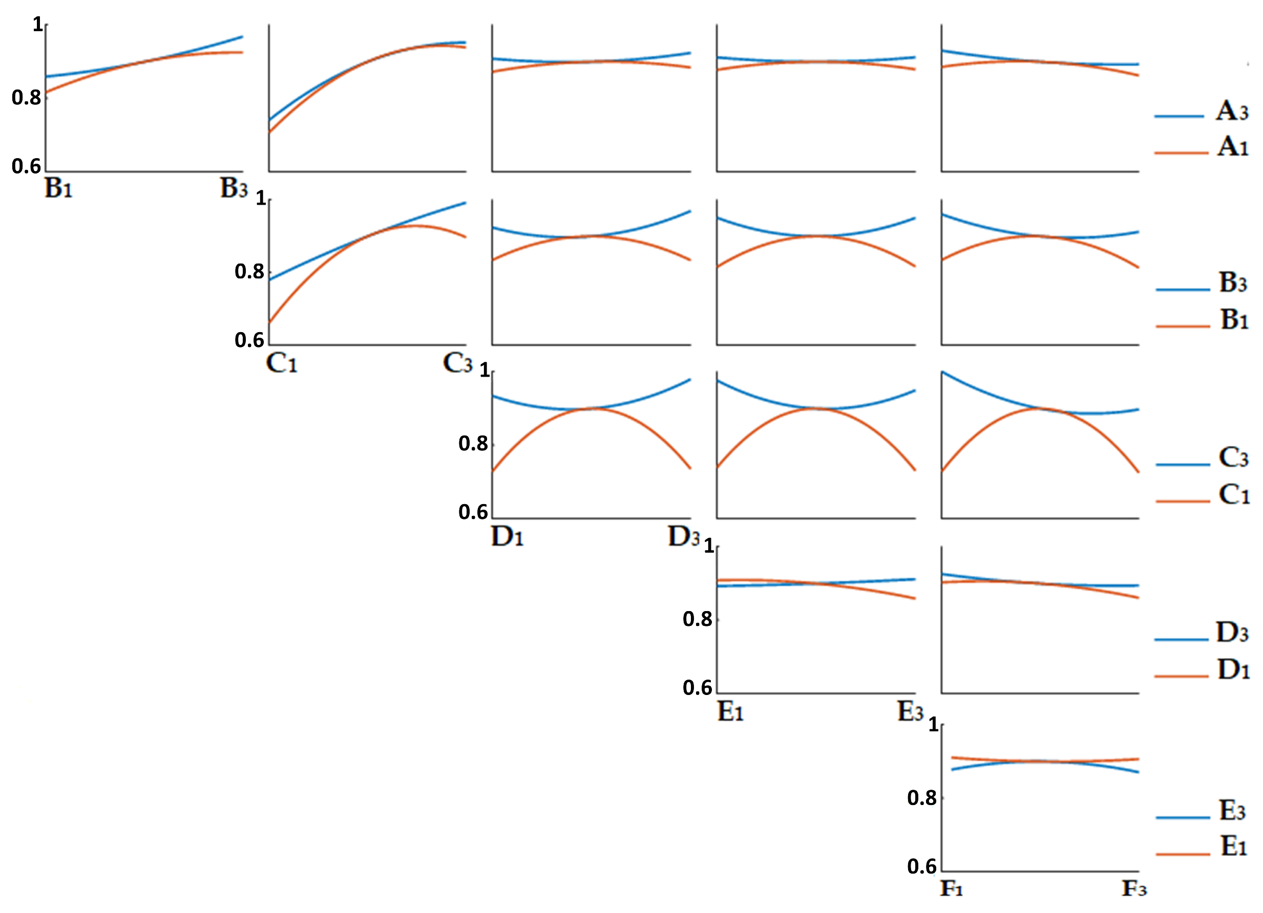
The interactive effect of the design variables on the average electromagnetic torque is shown in Figure 6. Each subplot has five values of the electromagnetic torque; for example, the interactive effect between the PM length A and PM width B has A1-B1, A3-B1, A1-B3, A3-B3, and the reference electromagnetic torque determined by the mean values, such as A2-B2. Thus, reducing the levels from three to two of each design variable reduces the 3D FEA computation costs heavily, whereas the reference electromagnetic torque is the same as that of the basic model of the spoke-type DSSR AFPM motor.
The maximum and minimum average torque are obtained with the C2-F1 and C1-B1 design variable combinations, respectively. The combinations of the two design variables that provide higher values of the electromagnetic torque than the basic model of the spoke-type DSSR AFPM motor are A-B3, A-C3, A3-D3, A3-E, A3-F1; B3-C3, B3-D, B3-E, B3-F; C3-D, C3-E, C3-F1; D3-E3, D3-F1; and E1-F [2]. Design variables without a suffix represent both the minimum and maximum values. Apparently, increasing the PM length A or width B increases the electromagnetic torque, and similarly, the electromagnetic torque increases due to the increased stator slot width C when placing more coil conductors.
The significant variation in the electromagnetic torque is due to the interaction of the slot width C with other design variables. The variation in the PM width B and PM length A with other design variables is coherent. However, the variation extent due to the interactive effect with the PM width is more than that of the PM length. The smaller the inner radius F, the larger the electromagnetic torque; however, a further decrease in the stator inner radius will limit the slot width, which limits the space for the stator winding. The tooth tip height and the slot opening width have better results when their combination is E1-D1 and E3-D3.

3.4. Latin Hypercube Sampling (LHS)

The interactive effect in Figure 6 shows that each design variable has specific and varying relationships with the other design variables. Therefore, for the LHS, same design variables of Table 2 are taken, and the discrete random values of each design variable are uniformly distributed, enabling a robust surrogate model of the spoke-type DSSR AFPM motor for electromagnetic optimization. The design variable ranges are constrained due to the physical limits as well as the electromagnetic performance goals of the spoke-type DSSR AFPM motor.
The range of the PM length and the PM width is reduced, i.e., A1-A2 and B1-B2, respectively, because of the reduced PM consumption, reduced torque ripple, and reduced cogging torque. Similarly, the range of the slot width and the inner stator radius is also reduced, i.e., C2-C3 and F2-F3, respectively, to provide more space for the stator winding. The sensitivity analysis effectively reduces the design variable ranges for having narrowed optimal performance zones for the PM and stator winding and iron core usage. Due to the high computation time of 3D FEA, forty experiments were conducted; however, increasing the number of experiments will provide a better impression near to all possible combinations for a global optimal solution. However, the sample size is based on a balance between computational costs and design space coverage, and it ensures the efficient exploration of the design space along with maintaining the stability of the results.
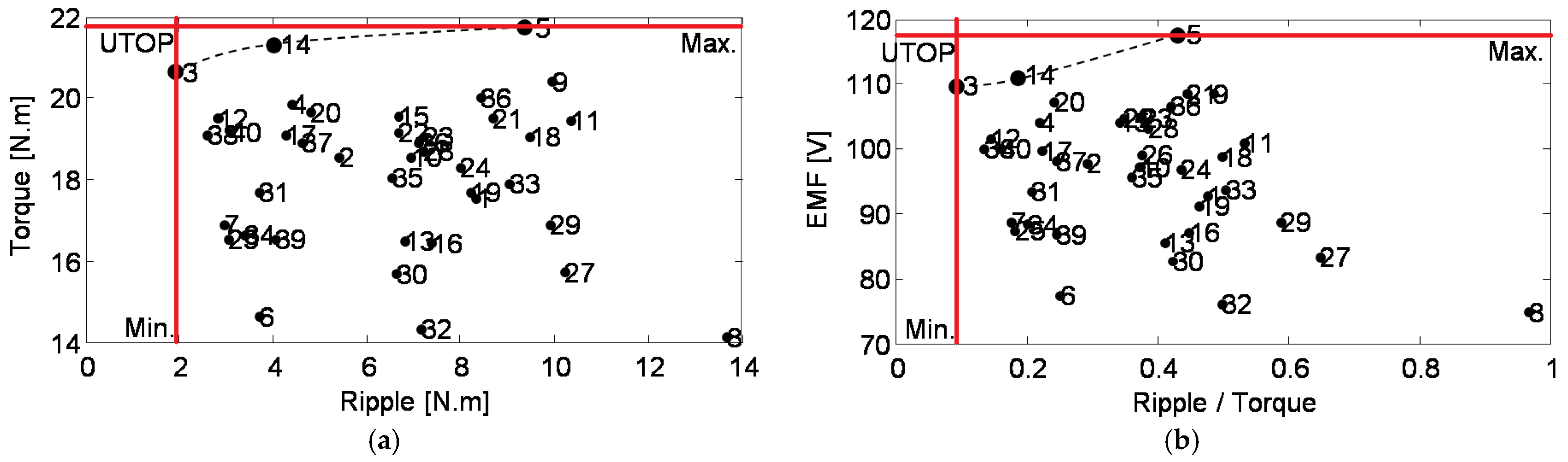
Using LHS, the distribution of the electromagnetic output characteristics of the spoke-type DSSR AFPM motor is provided in Figure 7. In the context of the Pareto front, the dashed line is the interpolation of the dominant experiments. Experiment no. 3 presents the least peak to peak torque ripple and the lowest ratio of torque ripple to electromagnetic torque. However, experiment no. 5 presents the highest values of the electromagnetic torque and back EMF. Experiment no. 14 presents compromised results between experiment no. 3 and 5. It presents higher electromagnetic torque and back EMF but also higher torque ripples than experiment no. 3 and vice versa with experiment no. 5. The utopia point (UTOP) represents the ideal target point where the electromagnetic torque and back EMF are at a maximum and the torque ripple is at a minimum.

4. Optimal Model

The parametrized optimal model of the spoke-type DSSR AFPM motor should have better no-load and load characteristics than the basic model and consume less material. Although experiments no. 3, 14 and 5 provide dominant results compared to the remaining experiments, the experiment no. 3 provides the least distant results from the UTOP. Therefore, experiment no. 3 is the optimal model of the spoke-type DSSR AFPM motor.

4.1. Confirmation of the Optimal Model

The spoke-type DSSR AFPM motor model, which has a low THD and high value of the back EMF and has low torque ripples and high electromagnetic torque was selected. A lower THD relative to the back EMF indicates better quality and efficiency, whereas lower torque ripples relative to the average electromagnetic torque improves the motor’s smoothness and reduces vibrations. Therefore, for the parametrically optimized model of the spoke-type DSSR AFPM motor, Equation (1) is the decisive factor or cost function:
D e c i s i o n = T H D E M F × R i p p l e T o r q u e
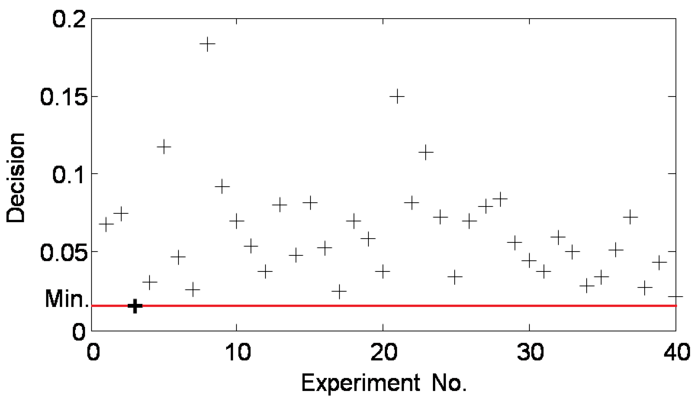
Equation (1) provides a single optimization goal, and it includes the fundamental no-load as well as load performance characteristics of the spoke-type DSSR AFPM motor. The distribution of Equation (1) with respect to each DoE is shown in Figure 8. Experiment no. 3 presents the minimum value of the cost function; therefore, it is the optimal model of the spoke-type DSSR AFPM motor. Equal weighting of the no-load and rated load characteristics reflects the design balance of the spoke-type DSSR AFPM motor’s performance quality and operational smoothness. However, it is worth mentioning that the single optimization goal is merely for reconfirmation, and it does not provide detailed information compared to the Pareto front and determined utopia point from the LHS. Therefore, experiment no. 3 is selected as the optimal model of the spoke-type DSSR AFPM motor from Figure 7, and it is reconfirmed from Figure 8.

4.2. Comparative Analysis of the Basic and Optimal Model

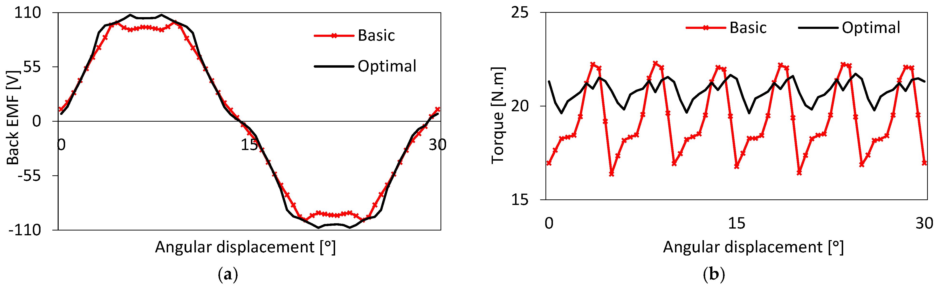
A comparative characteristic analysis between the basic and optimal models of the spoke-type DSSR AFPM motors is shown in Figure 9. The optimal model has improved the back EMF by 8% and the average electromagnetic torque by 6.95% by significantly reducing the torque ripples (181%) compared to the basic model of the spoke-type DSSR AFPM motor. However, the PM losses are reduced from 16.2 W to 15.65 W, and similarly, the core losses are also reduced from 81.99 W to 66.56 W. The reduction in the torque ripple is critical achievement, and it outweighs the modest but significant improvement in the back EMF and electromagnetic torque due to the geometrical change in the optimal spoke-type DSSR AFPM motor. The reduced torque ripple promises positive implications for reduced vibration and acoustic noise and better control stability in drive applications.
The change in the design variables from the basic to the optimized model is shown in Table 3. The selected parametrized optimal model of the spoke-type DSSR AFPM motor has a reduced PM width and length; therefore, the PM material utility is reduced by 7.03%. Additionally, optimal spoke-type DSSR AFPM has a slightly higher stator inner radius and an increased slot width, which decreases the stator core iron usage by 1.938%, and similarly, the rotor core iron usage is reduced by 2.24%. The active weight of the consumed stator winding is increased by 15.09% due to the increased slot width. Although the copper consumption is increased, the total active volume of the spoke-type DSSR AFPM motor is reduced by 1.512%.

5. Conclusions

The DoE method is effectively utilized in this study for the parametric optimization of a spoke-type DSSR AFPM motor. It is equally important to realize all the possible effects of the design variables on the output characteristics. Therefore, individual design variable effects, interactive effects of design variable pairs and the overall influence of the design variables on the electromagnetic output performance of the spoke-type DSSR AFPM motor are analyzed. The spoke-type DSSR AFPM motor has a high airgap flux density; therefore, torque ripples are significant, especially when having a low current density. The parametric optimization of the spoke-type DSSR AFPM motor has improved the back EMF, reduced the PM and core losses, significantly reduced the torque ripples and improved the electromagnetic torque. The active volume of the spoke-type DSSR AFPM motor is reduced, and the amount of PM and iron material consumption is reduced; however, copper consumption for the stator winding is increased.
The presented work presents the electromagnetic parametric optimization of a spoke-type DSSR AFPM motor, and future work will conduct its multi-objective optimization, considering thermal, efficiency, and cost constraints; therefore, a comprehensive analysis of losses, efficiency, and thermal performance will be undertaken. Additionally, experimental validation of the 3D FEA results will be conducted; hence, the manufacturing and system-level impacts of the material consumption of the spoke-type DSSR AFPM motor will be reevaluated by benchmarking against other AFPM motor designs. Additionally, motor control for an extended speed range will be developed to support and strengthen the spoke-type DSSR AFPM motor’s practical applicability.

Author Contributions

Conceptualization, Q.A.S.S.; methodology, Q.A.S.S.; software, Q.A.S.S.; formal analysis, Q.A.S.S.; investigation, Q.A.S.S.; resources, Q.A.S.S. and I.H.; data curation, Q.A.S.S.; supervision, I.H.; project administration, Q.A.S.S. and I.H.; funding acquisition, Q.A.S.S. All authors have read and agreed to the published version of the manuscript.

Funding

This research received no external funding.

Data Availability Statement

The data that support the findings of this study are available at https://doi.org/10.25593/open-fau-2172, Chapter 6: Parametric Optimization, Page: 79–93, accessed on 1 August 2025.

Acknowledgments

The authors acknowledge the support of Altair® for providing the 3D FEA license of Flux®. The corresponding author is grateful for the financial support provided by the Higher Education Commission (HEC) of Pakistan, Deutscher Akademischer Austauschdienst (DAAD) of Germany, The University of Larkano, and Friedrich-Alexander-Universität Erlangen-Nürnberg.

Conflicts of Interest

The authors declare no conflict of interest.

References

  1. Aydin, M.; Guven, M.K. Comparing Various PM Synchronous Generators: A Feasible Solution for High-Power, Off-Highway, Series Hybrid, Electric Traction Applications. IEEE Veh. Technol. Mag. 2014, 9, 36–45. [Google Scholar] [CrossRef]
  2. Syed, Q.A.S. Spoke Type Axial Flux Permanent Magnet Motor and its Flux Switching Variants. Ph.D. Thesis, University of Erlangen Nuremberg, Erlangen, Germany, 2024. [Google Scholar]
  3. Xuan, H.V.; Trong, V.N. Effective Electromagnetic Models for the Design of Axial Flux Permanent Magnet Generators in Wind Power. Eng. Proc. 2025, 104, 82. [Google Scholar] [CrossRef]
  4. Gong, J.; Zhao, B.; Huang, Y.; Semail, E.; Nguyen, N.K. Quantitative Comparisons of Outer-Rotor Permanent Magnet Machines of Different Structures/Phases for In-Wheel Electrical Vehicle Application. Energies 2022, 15, 6688. [Google Scholar] [CrossRef]
  5. Kim, H.-J.; Baek, S.-W. Multi-Objective Optimal Design of an Axial Flux Permanent Magnet Motor for In-Wheel Drive Considering Torque Ripple Reduction. Energies 2025, 18, 4936. [Google Scholar] [CrossRef]
  6. Choi, Y.; Song, D.; Yoon, S.; Koo, J. Comparison of Factorial and Latin Hypercube Sampling Designs for Meta-Models of Building Heating and Cooling Loads. Energies 2021, 14, 512. [Google Scholar] [CrossRef]
  7. Gadiyar, N.; Wang, B. Topology Optimization of Electric Machines: A Review. In Proceedings of the 2022 IEEE Energy Conversion Congress and Exposition (ECCE), Detroit, MI, USA, 9–13 October 2022; pp. 1–8. [Google Scholar] [CrossRef]
  8. Siddique, F.; Shastri, S.; Singh, B. Computational Investigation of Modeling Coupled Optimization Techniques for MCSRM Driving EV. IEEE Trans. Energy Convers. 2024, 39, 1793–1803. [Google Scholar] [CrossRef]
  9. Gillon, F.; Brochet, P. Shape Optimization of a Permanent Magnet Motor Using the Experimental Design Method. IEEE Trans. Magn. 1999, 35, 1278–1281. [Google Scholar] [CrossRef]
  10. Hwang, C.-C.; Li, P.-L.; Chuang, F.C.; Liu, C.-T.; Huang, K.-H. Optimization for Reduction of Torque Ripple in an Axial Flux Permanent Magnet Machine. IEEE Trans. Magn. 2009, 45, 1760–1763. [Google Scholar] [CrossRef]
  11. Parviainen, A. Design of Axial-Flux Permanent-Magnet Low-Speed Machines and Performance Comparison between Radial-Flux and Axial-Flux Machines. Ph.D. Thesis, Lappeenranta University of Technology, Lappeenranta, Finland, 2005. [Google Scholar]
  12. Sarac, V.; Minovski, D.; Aneva, S.; Janiga, P.; Smitkova, M.F.; Bogatinov, D.; Atanasova, A. Various Designs of Spoke-Type Permanent Magnet Motor for Performance Optimization. Machines 2025, 13, 375. [Google Scholar] [CrossRef]
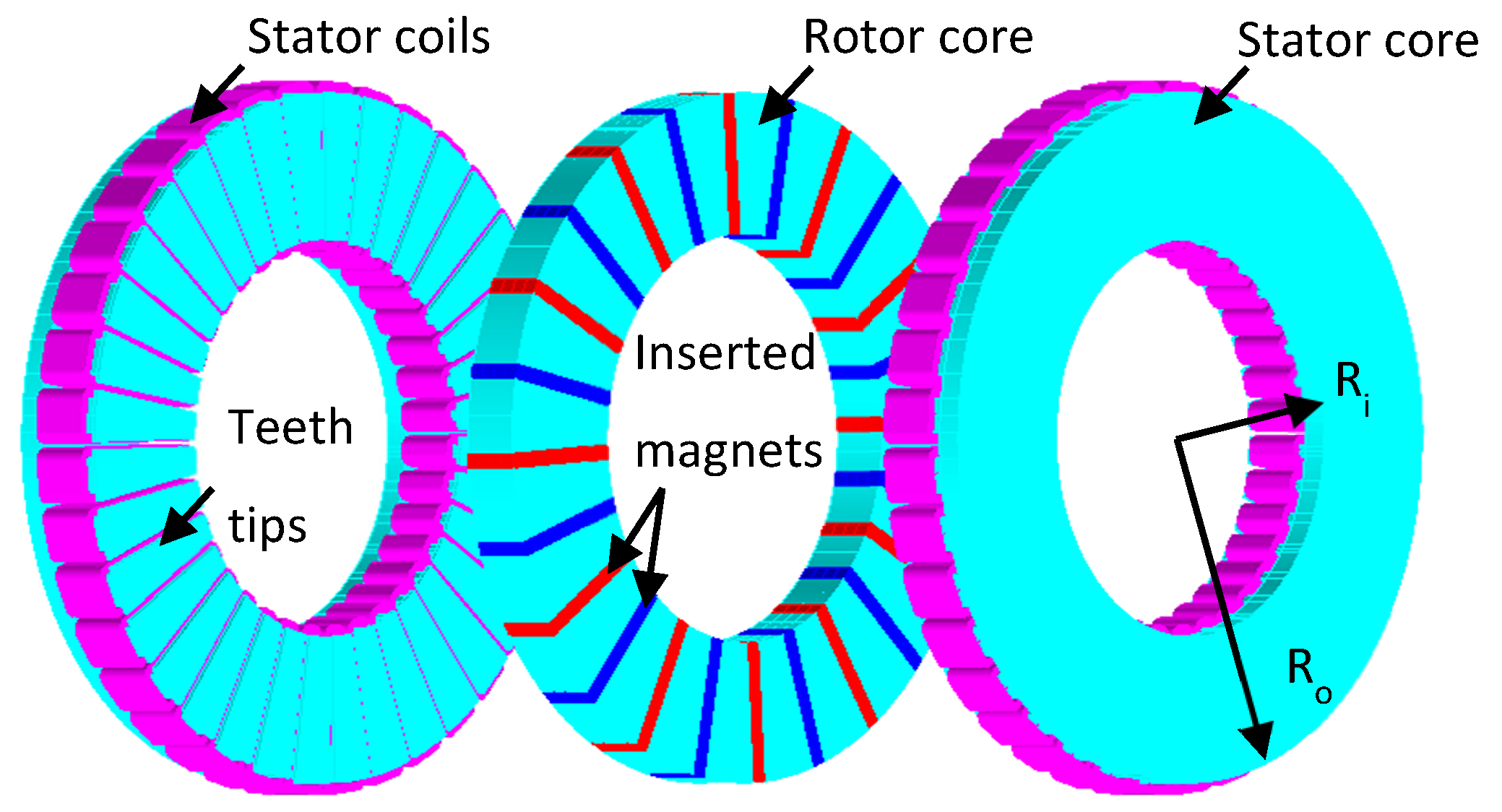
Figure 1. Basic model of the spoke-type DSSR AFPM motor, where Ro and Ri are the outer and inner radii of the machine, and red and blue color of the PMs represent the north and south poles.
Magnetism 06 00011 g001
Figure 2. Electromagnetic characteristics of the basic model of the spoke-type DSSR AFPM motor.
Magnetism 06 00011 g002
Figure 3. Representation of the design variables, where, A, B, C, D and E represent PM length, PM width, stator slot width, slot opening width, tooth tip height, and stator inner radius, respectively.
Magnetism 06 00011 g003
Figure 4. Main effect of each design variable on the output characteristics: (a) back EMF, (b) electromagnetic torque.
Magnetism 06 00011 g004
Figure 5. Main effect of each design variable on the cogging and torque ripples.
Magnetism 06 00011 g005
Figure 6. Interactive effect of the design variables on the electromagnetic torque. Per unit values of the electromagnetic torque are provided at the y-axis for the comparative interactive influence tendency of the design variables.
Magnetism 06 00011 g006
Figure 7. Distribution of the output characteristics of experiment 1 to 40 using the LHS method, where the dashed line represents the Pareto front and the interaction of the solid red lines represents the UTOP: (a) relationship between electromagnetic torque and torque ripple, (b) relationship between back EMF and ratio of electromagnetic torque to torque ripple [2].
Magnetism 06 00011 g007
Figure 8. Decisive factor output distribution to confirm the optimal model of the spoke-type DSSR AFPM motor, where + represents the decision value of each experiment, bold + represents the minimum decision value of experiment no. 3 and the red solid line reference minimum value line.
Magnetism 06 00011 g008
Figure 9. Comparative analysis between basic and the optimal model of the spoke-type DSSR AFPM motor: (a) back EMF, (b) electromagnetic torque.
Magnetism 06 00011 g009
Table 1. Geometrical specifications of the basic model of the spoke-type DSSR AFPM motor.
ParameterValue
Outer radius of machine90 mm
Axial length of machine53 mm
Stator slots36
Rotor pole pairs12
Rated speed750 rpm
Remanence of the PM1.08 T
Number of turns per phase576
Table 2. Range of the design variables.
SymbolDescriptionValue [mm]
APM length35~38
BPM width3~5
CSlot width6~9
DSlot opening width1~4
ETooth tip height0~2
FStator inner radius50~54
Table 3. Comparison of the geometric specifications of basic and optimal models of the spoke-type DSSR AFPM motor.
DescriptionBasic Model [mm]Optimal Model [mm]
Permanent magnet length3836.8
Permanent magnet width54.8
Stator slot width7.58.8
Stator slot opening width2.52.8
Tooth tip height10.2
Stator inner radius5252.7
Disclaimer/Publisher’s Note: The statements, opinions and data contained in all publications are solely those of the individual author(s) and contributor(s) and not of MDPI and/or the editor(s). MDPI and/or the editor(s) disclaim responsibility for any injury to people or property resulting from any ideas, methods, instructions or products referred to in the content.