Article

Semi-Active Vibration Control for High-Speed Elevator Using Magnetorheological Damper

Department of Production Engineering, Federal University of Technology-Paraná, Paraná-Doutor Washington Subtil Chueire St. 330, Ponta Grossa 84017-220, Brazil
*
Author to whom correspondence should be addressed.
Magnetism 2025, 5(2), 13; https://doi.org/10.3390/magnetism5020013
Submission received: 1 February 2025 / Revised: 22 May 2025 / Accepted: 5 June 2025 / Published: 8 June 2025

Abstract

This paper presents the results of investigating the application of magnetorheological fluids in controlling the lateral and angular vibrations of a high-speed elevator. Numerical simulations are performed for a mathematical model with two degrees of freedom. The lateral and rotational accelerations are analyzed for different travel speeds to determine passenger comfort levels. To attenuate the elevator vibrations, the introduction of a magnetorheological damper in parallel with the passive damper of the elevator rollers is considered. To semi-actively control the dissipative forces of the magnetorheological fluids, a State-Dependent Riccati Equation (SDRE control) is proposed. The numerical results demonstrate that using an MR damper makes it possible to reduce the acceleration levels of the elevator cabin, thus improving passenger comfort and reducing the elevator’s vibration levels and wear on the mechanical and electronic components of the elevator. In addition to the results, a detailed sensitivity analysis is presented.

1. Introduction

With the construction of increasingly tall buildings, the need for elevators with increasingly higher vertical displacement capacity has arisen. However, the upward and downward movements in the elevator shaft generate vibrations, discomfort for passengers, and wear on elevator components [1,2,3,4,5,6]. The elevator travel speed, deviations in the guide rail profile, and the dynamic parameters of the rolling guide shoe are the primary sources of vibration in the elevator cabin [1,2,3,4,5,6,7]. In [7], the influence of the operating speed of a high-speed elevator, the deviation of the guide rail profile, and the dynamic parameters of the rolling guide shoe on the horizontal vibration of the car and passenger comfort is presented [1,2,7].
With the need to reduce the vibration levels of the elevator cabin and increase its travel speed, research on control systems and actuators applied to lateral and angular acceleration control has grown recently [1,2,3]. In [8], a sliding mode controller is considered to reduce the horizontal vibrations of the elevator cabin caused by irregularities in the guide rail. In [9], the horizontal vibrations caused by guide “casters” in the high-speed elevator car are examined. In [10], the vibrations of the elevator car generated by the irregularity of the guide rail, uncertainty in the modeling of the guide shoe, wear, and the aging of the spring between the guide shoe bearing and the guide rail are investigated. Based on this, an H2/H∞ control system is proposed to reduce the vibrations. In [11,12], the vibrations originating from the elevator lifting cables are investigated.
This paper proposes the control of the lateral and angular vibrations of an elevator with two degrees of freedom using a magnetorheological (MR) damper. The MR damper force is regulated by controlling the electrical voltage applied to the damper coil, thus acting on the magnetorheological fluid in the damper. To determine the relationship between electrical voltage and damper force, the LuGre friction model is used, and an SDRE (State-Dependent Riccati Equation) control is used to determine the ideal force to be applied in the control. Unlike in the works [1,3,6,7,13], in which only lateral displacements are considered, this paper assesses lateral and angular displacements and the control of their displacements. To control lateral and angular vibrations, an MR damper is included parallel to the roller damper of the elevator damping system. Control through the use of the MR damper builds on the works [2,4,8,9,10,11], which consider only the lateral and angular vibrations of the elevator without considering the MR damper. The use of the MR damper in this paper is due to its importance and relevance to research in the area of smart magnetic materials and vibration control, as well as its versatility. The number of research studies on applying MR dampers has increased annually, with them being used in vehicle suspension systems [14,15,16,17], in the semi-active damping control of aircraft landing gear [18,19,20], in transverse suspension systems for railway vehicles [21,22,23], in smart prosthetic knee joints [24], and in Earthquake-resistant building protection [25,26].
Magnetorheological (MR) fluids are smart materials considered semi-active devices and belong to the class of controllable fluids. They comprise significant amounts of micrometric-sized, highly magnetizable solid particles (up to 50% vol) in a non-magnetizable liquid, such as mineral and silicone oils, polyesters, polyethers, synthetic hydrocarbons, and water. Typically, the solid particles are carbonyl iron particles, and they are used due to their high saturation magnetization. The main characteristic of MR fluids is their ability to change from viscous liquids to semi-solids in milliseconds when exposed to a magnetic field. This characteristic gives them a simple architecture and a fast response when interfacing electronic controllers and mechanical systems, thus enabling their use in mechanical systems requiring semi-active vibration control or torque transmission [27,28,29,30]. Valve mode, direct cut mode, and squeezed film mode are the three basic design forms of equipment that uses MR fluids as actuators. In valve mode, the magnetic poles are fixed, and the fluid is forced to pass between these poles, as illustrated in Figure 1.
Valve mode can be used in hydraulically controlled valve dampers since the poles perform the valve function as the magnetic field strength varies, altering the viscosity of the fluid passing between the poles. This variable resistance to fluid flow allows the use of MR fluid in viscous dampers and other electrically controllable devices [27].
In [31], an MR damper was used to control the vibrations of the wheel motor of an electric vehicle. Damper force control was performed by adjusting the electrical voltage estimated by the Bouc-Wen mode and using a PID controller. Numerical results considering MATLAB/Simulink software were presented to demonstrate the effectiveness of the proposed control. In [32], an MR damper in vehicle seat suspension is considered. A narrowband-frequency semi-active control (NFSSC) algorithm is proposed to optimize vibration suppression. Experimental results demonstrate the effectiveness of the MR damper as a semi-active vibration control. In [33], the damping performance of MR dampers is investigated in vehicle vibration control to improve vehicle ride quality. MR damper force is controlled by regulating the electrical current applied to the damper coil. In [34], the control of the electrical current of the MR damper is proposed, considering the damper in a semi-active suspension system applied to vehicle suspension. Numerical results demonstrated the proposed control’s effectiveness and performance in the semi-active suspension system based on the MR feedback damper. In [7], fuzzy control is considered for the electric current control of a magnetorheological damper used in the vibration control of a high-speed elevator.

2. Materials and Methods

2.1. Mathematical Model of the Elevator

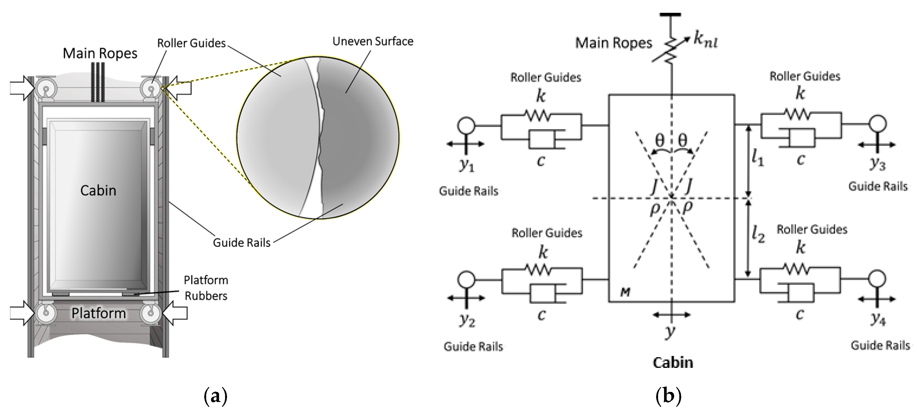
Figure 2 presents a dynamic representation of the elevator movements, with two degrees of freedom considered in this model. In Figure 2b, (y) is the translation of the cabin in the horizontal direction, and (θ) is its rotation around the centroid. Guide shoes and their rollers correspond to the contact of the elevator cabin with the guide rails. In vertical movement, the steel cable’s rigidity is considered an elastic spring with a cubic stiffness coefficient [2,4,8,9,10,11].
The roller guide shoes are composed of a spring and a shock absorber in parallel, as can be seen in Figure 1, where y1, y2, y3, and y4 are the displacements of the four guide shoes in the horizontal direction, excited by the unevenness of the guide rails; knl represents the coefficient of stiffness of the elevator cables with reference to the tilting movement of the cabin.
Considering Figure 2, we can determine the horizontal displacement of the four guide shoes by the following equation [2]:
y 1 = y 3 = y l 1 θ y 2 = y 4 = y l 2 θ
The deformation of the springs and shock absorbers of the shoes can be determined by the following equations [21]:
q 1 = y 1 y 1 = y l 1 θ y 1 q 2 = y 2 y 2 = y + l 2 θ y 2 q 3 = y 3 y 3 = y l 1 θ y 3 q 4 = y 4 y 4 = y + l 2 θ y 4
The mathematical modeling of the lateral and angular vibrations of the elevator can be obtained considering the dynamic characteristics of the elastic and damping elements and the D’Alembert principle [2], including the influence of the elevator hoisting cable [3].
y ¨ = α 1 y ˙ α 2 y α 3 y 3 + α 4 θ ˙ + α 5 θ + α 6 θ 3 + α 7 y ˙ 1 α 8 y 1 + α 9 y ˙ 2 α 10 y 2 + α 11 y ˙ 3 α 12 y 3 + α 13 y ˙ 4 α 14 y 4 θ ¨ = β 1 y + β 2 θ + β 3 y 3 + β 4 θ 3 + β 3 y ˙ + β 4 θ ˙ β 5 y 1 + β 6 y 2 β 7 y 3 + β 8 y 4 β 9 y ˙ 1 + β 10 y ˙ 2 β 11 y ˙ 3 + β 12 y ˙ 4
where α 1 = c 1 + c 2 + c 3 + c 4 M , α 2 = k 1 + k 2 + k 3 + k 4 M , α 3 = k n l M , β 7 = l 1 k 3 J , β 8 = l 2 k 4 J , α 4 = c 1 l 1 c 2 l 2 + c 3 l 1 c 4 l 2 M , α 5 = k 1 l 1 k 2 l 2 + k 3 l 1 k 4 l 2 M , α 6 = k n l l 1 M , α 7 = c 1 M , α 8 = k 1 M , α 9 = c 2 M , α 10 = k 2 M , α 11 = c 3 M , α 12 = k 3 M , α 13 = c 4 M , α 14 = k 4 M , β 1 = l 2 k 2 + k 4 + l 1 k 1 + k 3 J , β 2 = l 2 k 2 + k 4 l 1 2 k 1 + k 3 J , β 3 = k n l l 1 J , β 4 = k n l l 1 2 J , β 5 l 2 c 2 + c 4 + l 1 c 1 + c 3 J , β 6 l 2 2 c 2 + c 4 l 1 2 c 1 + c 3 J , β 7 = l 1 k 1 J , β 8 = l 2 k 2 J , β 9 = l 1 k 3 J , β 10 = l 2 k 4 J , β 11 = l 1 c 1 J , β 12 = l 2 c 2 J , β 13 = l 1 c 3 J , and β 14 = l 2 c 4 J .
c1, c2, c3, and c4 are the equivalent dampings of the guide shoe (Ns/m), J the moment of inertia of the car (kgm2), k1, k2, k3, and k4 the equivalent stiffness of the guide shoe (N/m), l1 the distance between the car system mass center and the upper guide shoe (m), l2 the distance between the car system mass center and the lower guide shoe (m), “M” the mass of the car system (kg), Δm the rated load of the car (kg), v the vertical velocity of the elevator (m/s), y the horizontal displacement (m), θ the angular displacement around the centroid (rad), and knl the coefficient of stiffness of the elevator cables with reference to the tilting movement of the cabin (N/m). The external vibrations associated with the elevator’s travel speed are represented by y 1 , y 2 , y 3 , y 4 , y ˙ 1 , y ˙ 2 , y ˙ 3 , and y ˙ 4 .
Equation (3) can be represented in a system of first-order differential equations:
x ˙ 1 = x 2 x ˙ 2 = α 1 x 2 α 2 x 1 α 3 x 1 3 + α 4 x 4 + α 5 x 3 + α 6 x 3 3 + α 7 y ˙ 1 α 8 y 1 + α 9 y ˙ 2 α 10 y 2 + α 11 y ˙ 3 α 12 y 3 + α 13 y ˙ 4 α 14 y 4 x ˙ 4 = x 4 x ˙ 4 = β 1 x 1 + β 2 x 3 + β 3 x 1 3 + β 4 x 3 3 + β 3 x 2 + β 4 x 4 β 5 y 1 + β 6 y 2 β 7 y 3 + β 8 y 4 β 9 y ˙ 1 + β 10 y ˙ 2 β 11 y ˙ 3 + β 12 y ˙ 4
where x 1 = y , x 2 = y ˙ , x 3 = θ , and x 4 = θ ˙ .
Alternatively, it can be expressed in the following matrix form:
x ˙ 1 x ˙ 2 x ˙ 3 x ˙ 4 = 0 1 0 0 α 2 α 3 x 1 2 α 1 α 5 + α 6 x 3 2 α 4 0 0 0 1 β 1 + β 3 x 1 2 β 3 β 4 x 3 2 + β 2 β 4 x 1 x 2 x 3 x 4 + 0 α 6 y ˙ 1 α 7 y 1 + α 8 y ˙ 2 α 9 y 2 + α 10 y ˙ 3 α 11 y 3 + α 12 y ˙ 4 α 13 y 4 0 β 5 y 1 + β 6 y 2 β 7 y 3 + β 8 y 4 β 9 y ˙ 1 + β 10 y ˙ 2 β 11 y ˙ 3 + β 12 y ˙ 4

2.2. Proposed Elevator Vibration Control System

To reduce the vibration levels of the elevator cabin, the introduction of magnetorheological dampers in parallel with the passive roller dampers will be considered, as shown in Figure 3.
Considering the costs of the MR damper control system, the control proposal presented in Figure 3 aims to reduce control costs and enable the best reductions in elevator vibration levels in the case of using only one MR damper.
In Equation (6), we present the system with the proposed control.
x ˙ 1 = x 2 x ˙ 2 = α 1 x 2 α 2 x 1 α 3 x 1 3 + α 4 x 4 + α 5 x 3 + α 6 x 3 3 + α 7 y ˙ 1 α 8 y 1 + α 9 y ˙ 2 α 10 y 2 + α 11 y ˙ 3 α 12 y 3 + α 13 y ˙ 4 α 14 y 4 α 14 F m r x ˙ 4 = x 4 x ˙ 4 = β 1 x 1 + β 2 x 3 + β 3 x 1 3 + β 4 x 3 3 + β 3 x 2 + β 4 x 4 β 5 y 1 + β 6 y 2 β 7 y 3 + β 8 y 4 β 9 y ˙ 1 + β 10 y ˙ 2 β 11 y ˙ 3 + β 12 y ˙ 4 + β 13 F m r
where α 14 = 1 M and β 13 = l 1 J .

2.3. Mathematical Model for MR Damper

The LuGre friction model was considered in this paper because it more accurately describes the characteristics of viscous sliding motion, friction hysteresis, pre-sliding displacement, and variable maximum static friction force in the friction process, features observed in MR fluids, where shear stress is generated by the deflection of particle chains [35,36,37]. To include the nonlinear friction phenomena of magnetorheological dampers and their hysteresis effects, this paper will consider the LuGre friction model, as presented in Equation (7) [36,38]:
F m r d = σ a z + σ 0 z V + σ 1 z ˙ + σ 2 y ˙ + σ b y ˙ V z ˙ = y ˙ σ 0 a 0 y ˙ z
where Fmrd is the damping force, V is the input voltage, z is the internal state variable, and y ˙ is the velocity of the damper piston, with σ 0 , σ 1 , σ 2 , σ a , σ b , and a 0 being constant values.
Considering Equation (7), we can determine the electrical voltage dependent on the desired force F m r d by isolating the variable V :
V = F m r d σ a z σ 1 z ˙ σ 2 y ˙ σ 0 z + σ b y ˙
Considering the case of a control strategy, to determine the desired force, F m r d , we have a maximum limit for the electrical voltage ( V max ), F m r d = U , and negative electrical voltages are not used. In this case, the rule for obtaining the electrical voltage is given by the following equation:
ν = i f V < 0                           V = 0 i f 0 < V < V max   V = U σ a z σ 1 z ˙ σ 2 y ˙ σ 0 z + σ b y ˙ i f V > V max                 V = V max

2.4. Electrical Voltage Control Project by SDRE Control

Consider system (6) in the following form:
X ˙ = A X + B U + G
where X is the states of the system, A(X) is the state matrix, B is the control matrix, U is the feedback control, and G is the terms that do not contain the states.
For system (6), we have the following matrices:
X = x 1 x 2 x 3 x 4 , A = 0 1 0 0 α 2 α 3 x 1 2 α 1 α 5 + α 6 x 3 2 α 4 0 0 0 1 β 1 + β 3 x 1 2 β 3 β 4 x 3 2 + β 2 β 4 , B = 0 0 α 14 0 0 0 0 β 13 , and G ( t ) = 0 α 6 y ˙ 1 α 7 y 1 + α 8 y ˙ 2 α 9 y 2 + α 10 y ˙ 3 α 11 y 3 + α 12 y ˙ 4 α 13 y 4 0 β 5 y 1 + β 6 y 2 β 7 y 3 + β 8 y 4 β 9 y ˙ 1 + β 10 y ˙ 2 β 11 y ˙ 3 + β 12 y ˙ 4 .
The feedback control is obtained from the following [39]:
U = R 1 B T P e
where e = [ X X * ] , X is the states of the system, and X * is the desired states.
The matrix P is obtained from the following [39]:
A T P + P A P B R 1 B T P + Q = 0
The functional cost considered for U is given by the following [40]:
J = 1 2 0 ( e T Q e + U T R U ) d t
where Q and R are positive definite matrices.
In this paper, Q and R, diagonal matrices, will be considered, with each term of the diagonal determining the weight of the gain for each state of the system.
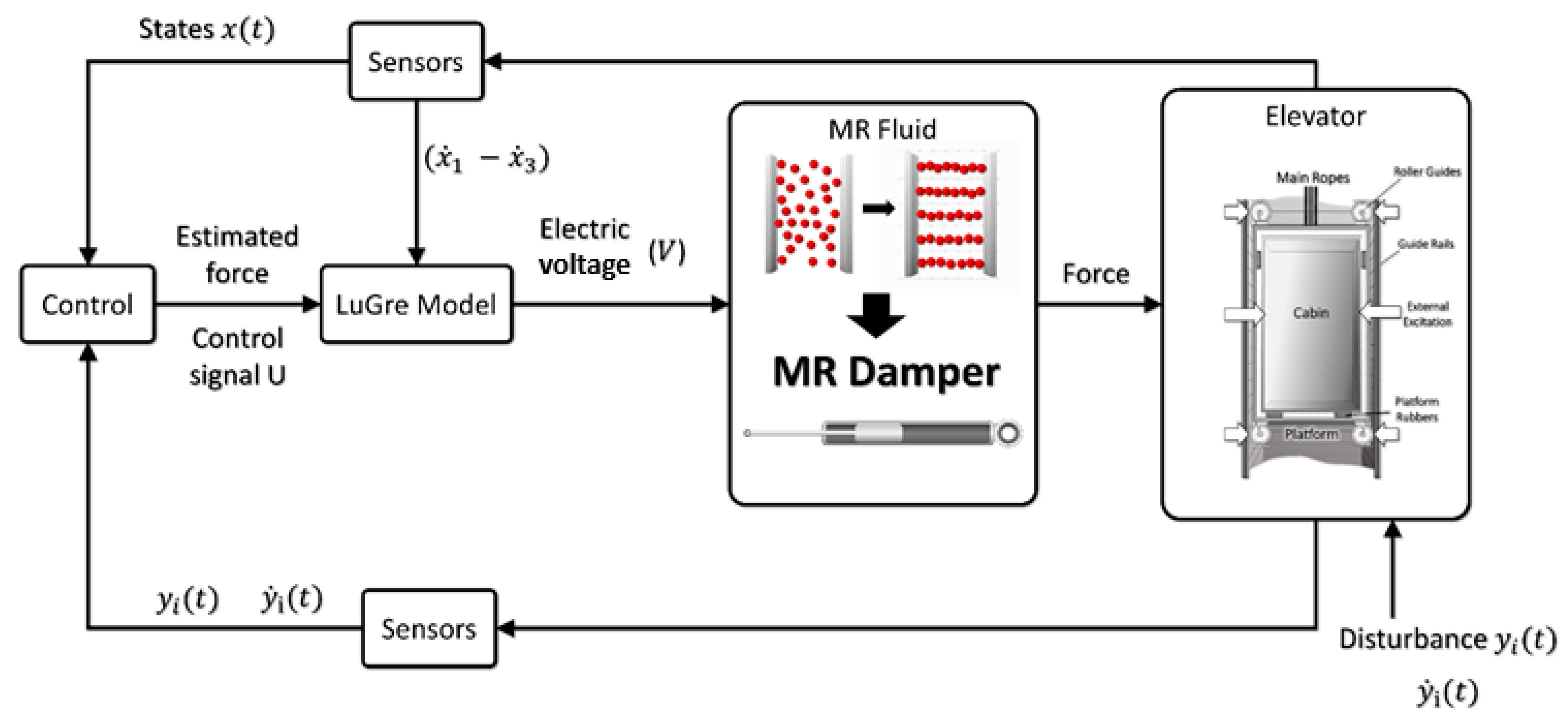
The proposed control strategy can be observed in Figure 4.

3. Results

This section presents the results of numerical simulations for the system without an MR damper and the system with an MR damper controlled through LQR control, as shown in Figure 4.
Most of the vibrations in high-speed elevators are caused by irregularities in the guide rails [40]. In this paper, for computational simulations, a slight deformation in the guide rail will be considered using the following equation:
y 1 = A d sin ( ω ( t + t 0 ) ) y 2 = A d sin ( ω t ) y 3 = y 4 = 0
Equation (14) represents the vibrations originating from the guide rail connections [21], where ω = 2 π ν λ , λ is the length of the excitation wave signal, ν is the elevator travel speed, and A d is the displacement amplitude.
The fourth-order Runge–Kutta method with an integration step h = 0.01 is used for the numerical integrations, and the following parameters are used for the simulations: k 1 = 10 5 (N/m), k 2 = 10 5 (N/m), k 3 = 10 5 (N/m), k 4 = 10 5 (N/m), c 1 = 10 3 (Ns/m), c 2 = 10 3 (Ns/m), c 3 = 10 3 (Ns/m), c 4 = 10 3 (Ns/m), l 1 = 2.8 (m), l 2 = 3.7 (m), M = [ 1500 : 2000 ] (kg), J = 8090 (kgm2), k n l = 219027 * 10 2 (N/m), v = [ 1 : 10 ] (m/s), A d = 0.01 (m), λ = 5 (m), t 0 = ( l 1 + l 2 ) / v (s), σ 0 = 533333.33 (N/(mV)), σ 1 = 1066.66 (Ns/m), σ 2 = 100 (Ns/m), σ a = 266666.66 (N/m), σ b = 533.33 (Ns/(mV)), and a 0 = 0.00003 (V/N) [1,2,36].
c1, c2, c3, and c4 are the equivalent dampings of the guide shoe (Ns/m), J the moment of inertia of the car (kgm2), k1, k2, k3, and k4 the equivalent stiffness of the guide shoe (N/m), l1 the distance between the car system mass center and the upper guide shoe (m), l2 the distance between the car system mass center and the lower guide shoe (m), “M” the mass of the car system (kg), Δm the rated load of the car (kg), v the vertical velocity of the elevator (m/s), y the horizontal displacement (m), θ the angular displacement around the centroid (rad), and knl the coefficient of stiffness of the elevator cables with reference to the tilting movement of the cabin (N/m).

3.1. Numerical Simulations for the Passive System

Considering the importance of passenger comfort, acceleration levels will be considered as the variable to be analyzed in computer simulations and for reduction in the control design. In this research, acceleration in RMS will be considered, as it is commonly used as a parameter to measure passenger comfort. A variation in deformity A d = 0.01 was considered in this research to extrapolate the deformation levels of the guide rails.
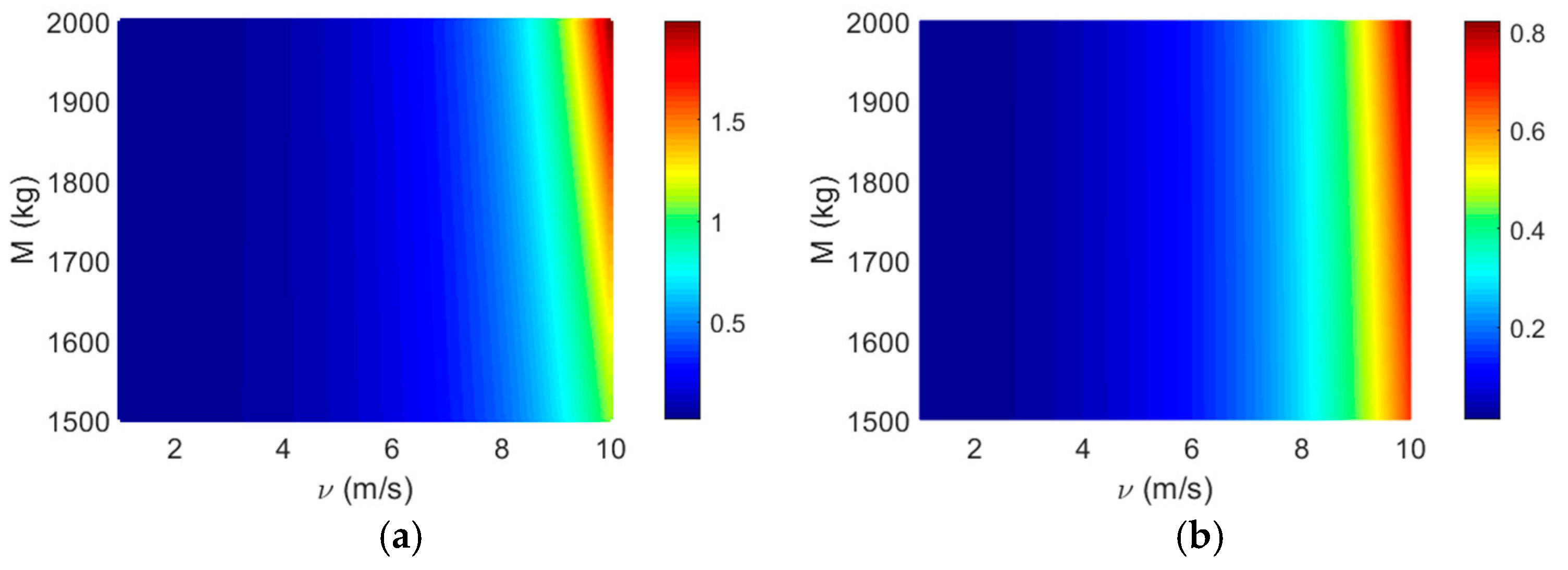
Figure 5 shows the variations in lateral and angular accelerations, considering the variation in elevator mass (variation in the number of passengers) and elevator velocity, considering M = [ 1500 : 2000 ] and v = [ 1 : 10 ] .
As shown in the results in Figure 5, the elevator mass (M) variation does not significantly affect the cabin acceleration levels. However, the travel speed is highly relevant to the increase in cabin acceleration and, thus, the discomfort of passengers.
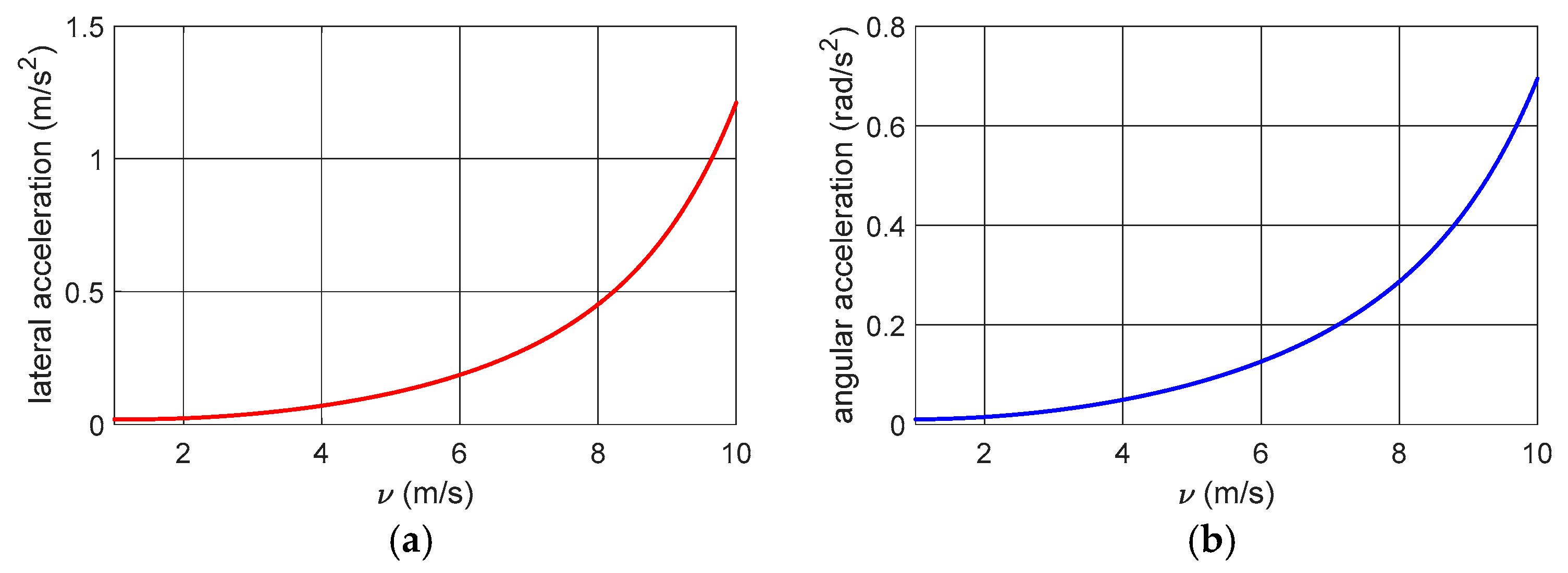
Figure 6 shows the variation in accelerations for the case of M = 1600 kg.
As we can see, the accelerations increase significantly as we increase the elevator’s travel speed. To reduce the vibrations that cause these high levels of acceleration, in the following sections, the inclusion of control in the elevator damping system will be considered, considering the elevator at a high speed of v = 10 (m/s) and M = 1600 kg.

3.2. Numerical Simulations for the System with Active Control

Considering the system with control (11), and to obtain the gains of the SDRE control, the following matrices will be considered:
Q = 10 6 0 0 0 0 10 6 0 0 0 0 10 6 0 0 0 0 10 6 and   R = 10 2
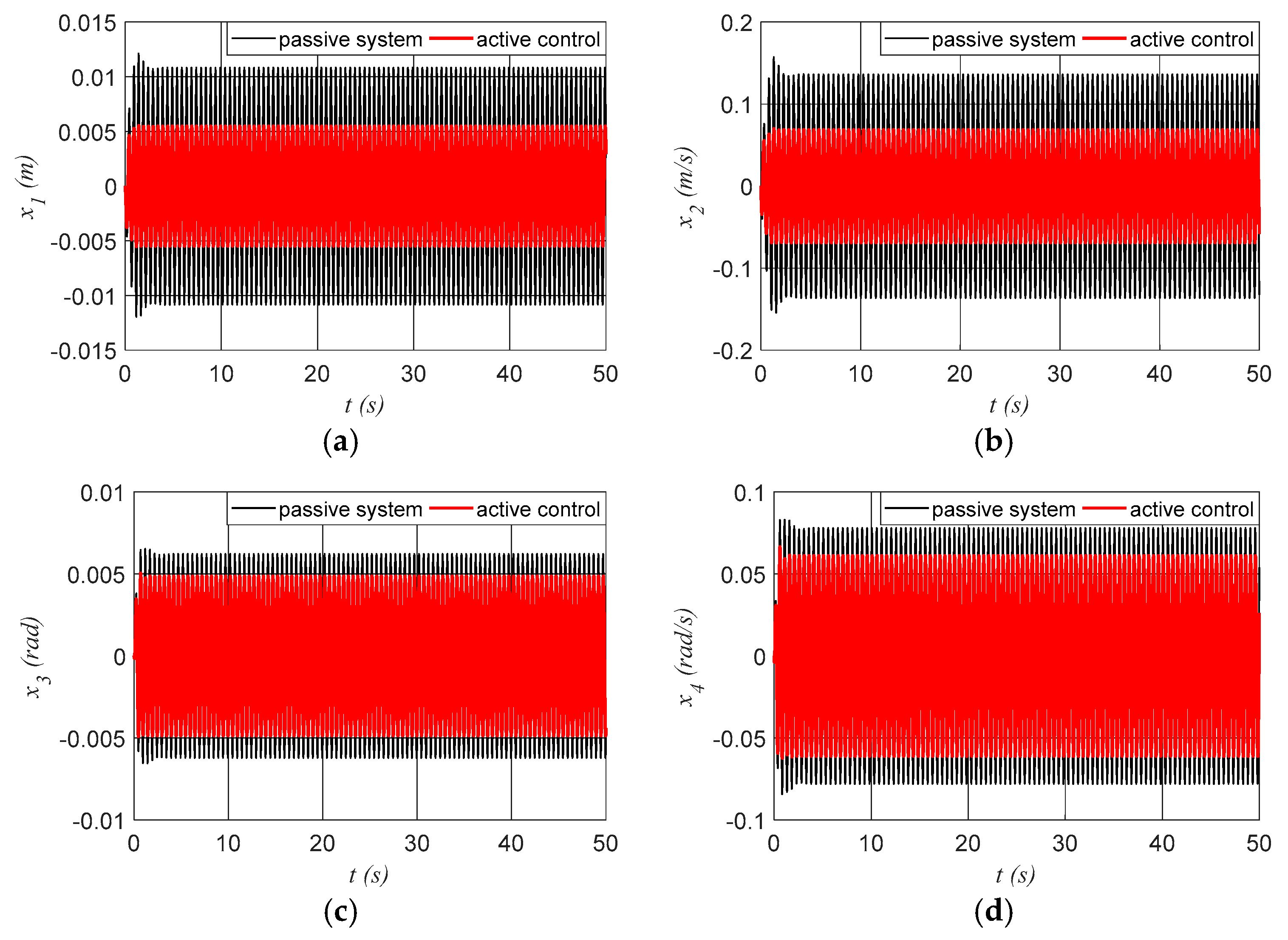
Figure 7 shows the lateral and angular displacements and their velocities for systems with active control.
As we can see in Figure 7, with the control, it was possible to significantly reduce the elevator’s vibrations, thus contributing to preserving its mechanical and electronic components.
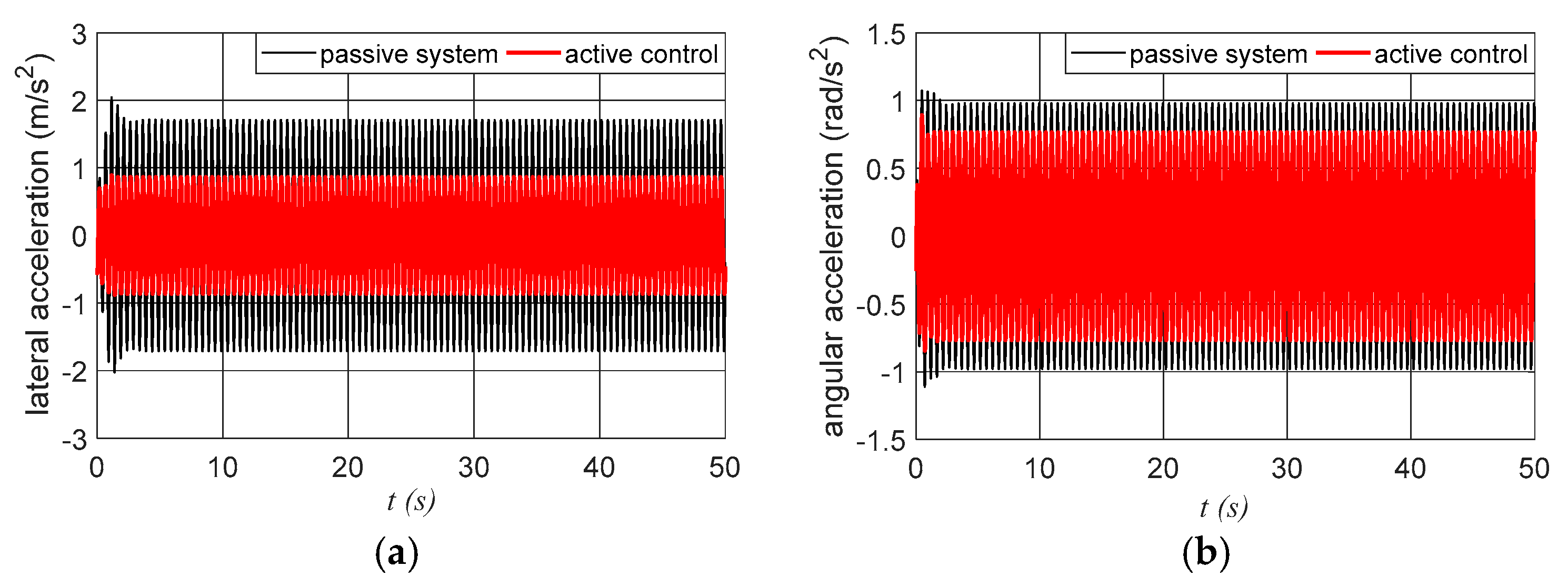
In Figure 8, we can observe the variation in the lateral and angular acceleration of the cabin.
Analyzing the results presented in Figure 8, we can observe that the control also reduced the cabin accelerations. Considering the RMS, we observe that the lateral acceleration for the system without control was 1.2106 (m/s2), and for the system with control, the acceleration was 0.6103 (m/s2), a reduction of 42% in lateral acceleration. In the case of angular acceleration, we have an angular acceleration of 0.6947 (rad/s2) for the passive system and an acceleration of 0.5429 (rad/s2) for the active system, which indicates a reduction of 9.96% in angular acceleration.
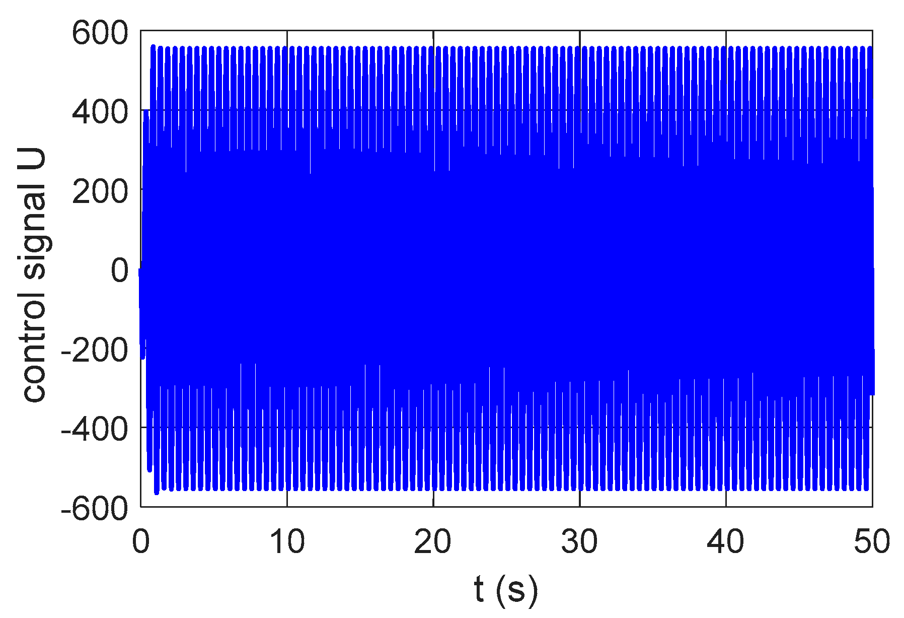
Figure 9 shows the values of the variation in the control signal U, according to the elevator displacement.
The results presented in Figure 9 represent the force required for an active or semi-active damper, which was considered to be included parallel to the damper c1.
As can be seen, the control effectively reduced the elevator vibrations; however, a specific actuator was not considered, which is why the results presented also apply to actuation systems other than an MR damper.

3.3. Numerical Simulations for the System with Semi-Active Control by an MR Damper

Considering the application of the MR damper, it is necessary to determine the electrical voltage to be applied to the damper coil and consider only the dissipative force in the control. Thus, it is necessary to take Equation (7) into consideration in the control signal. In this case, we have a semi-active control system.
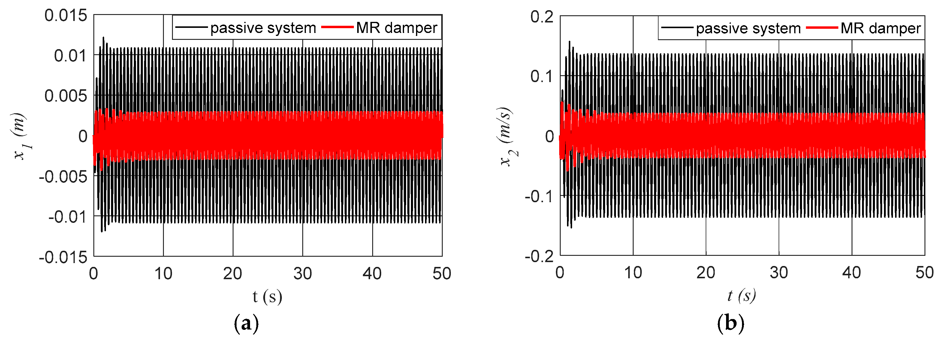
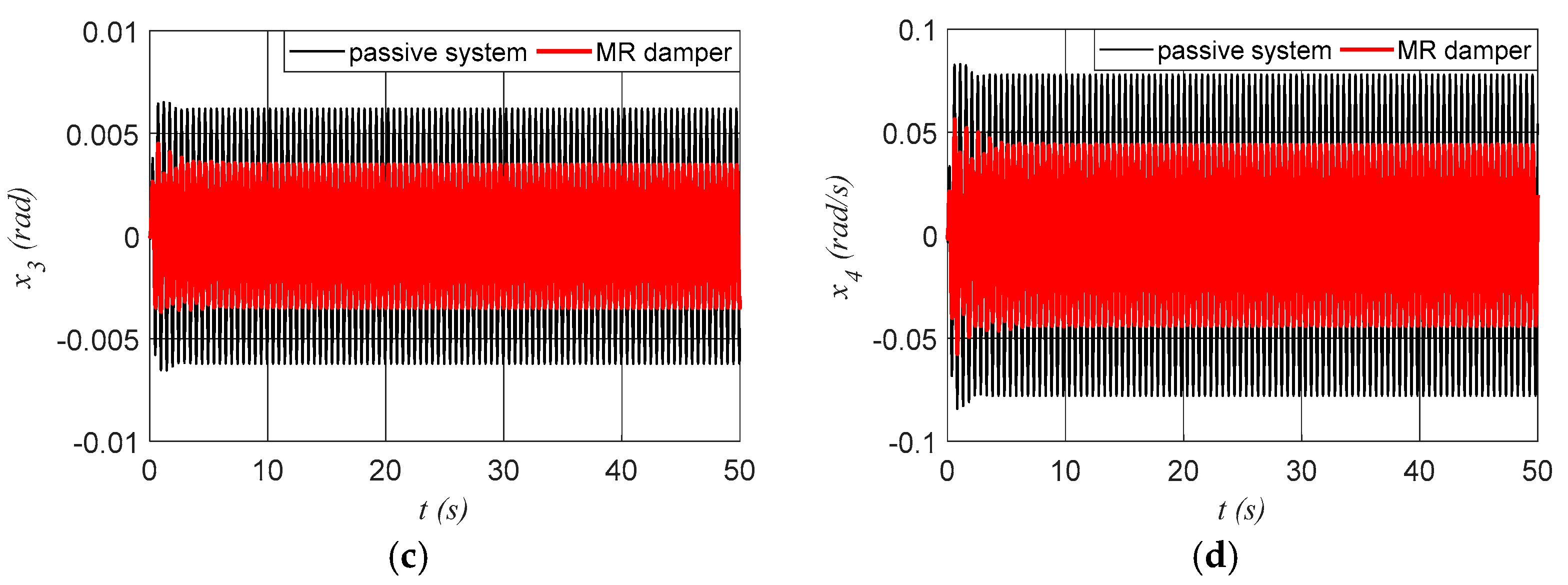
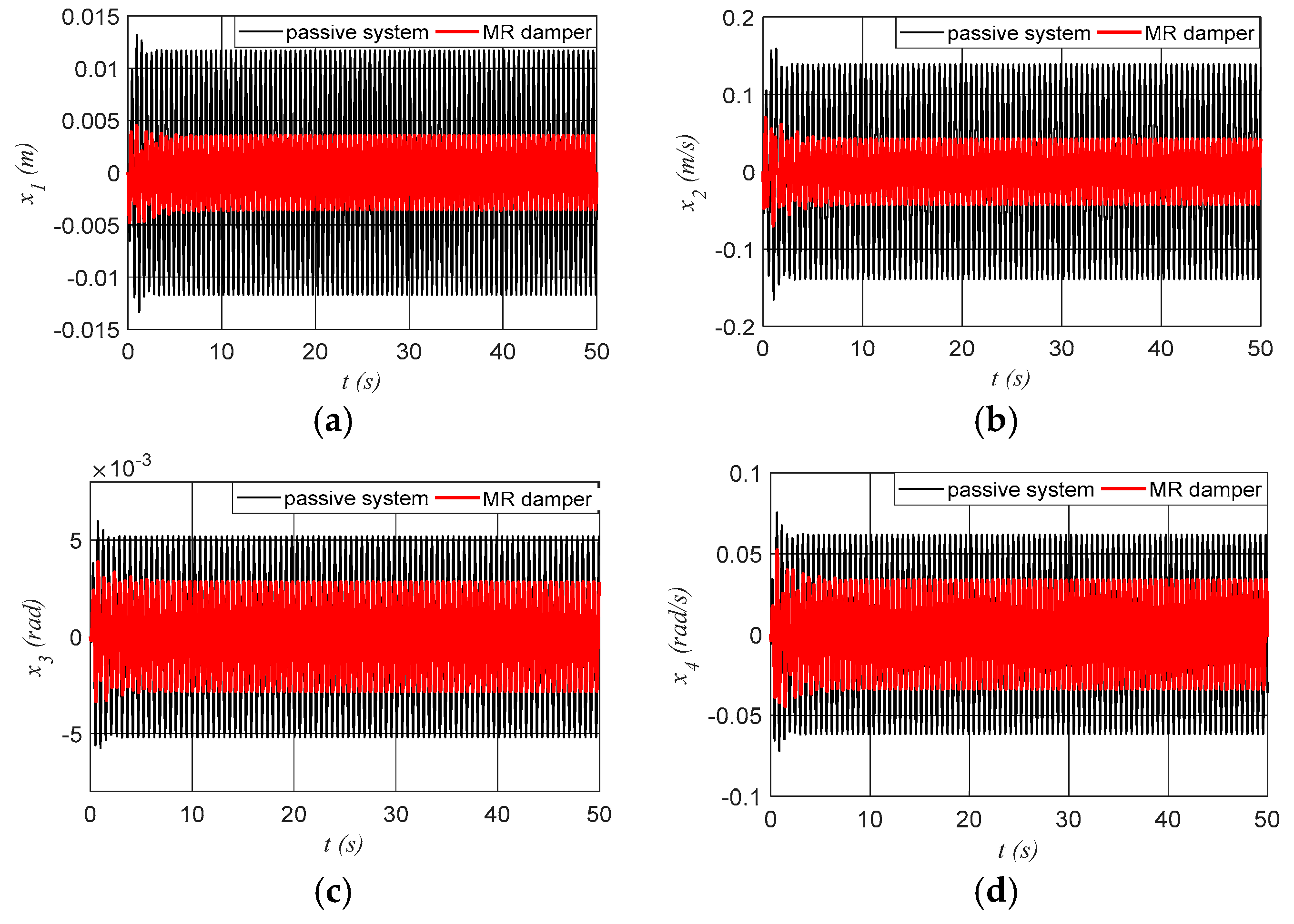
Figure 10 shows the lateral and angular displacements and their velocities for systems with a controlled MR damper.
The results demonstrate that the use of an MR damper as a semi-active control effectively reduces elevator cabin vibrations.
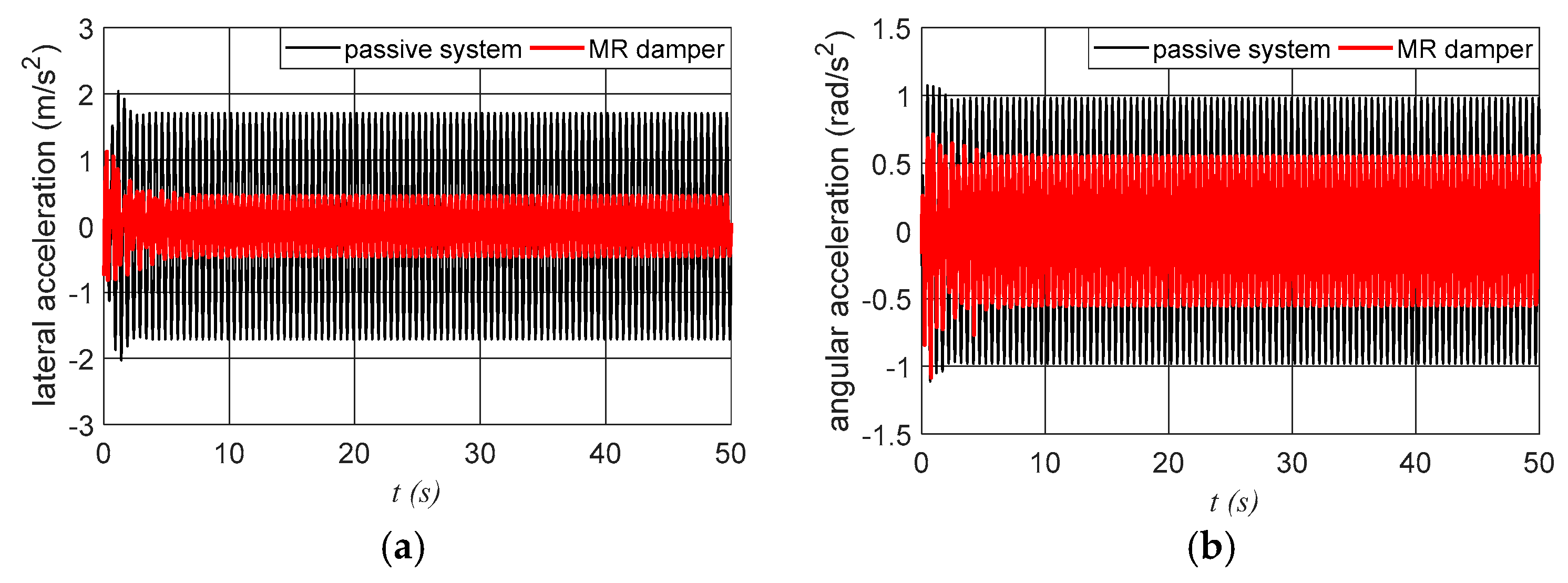
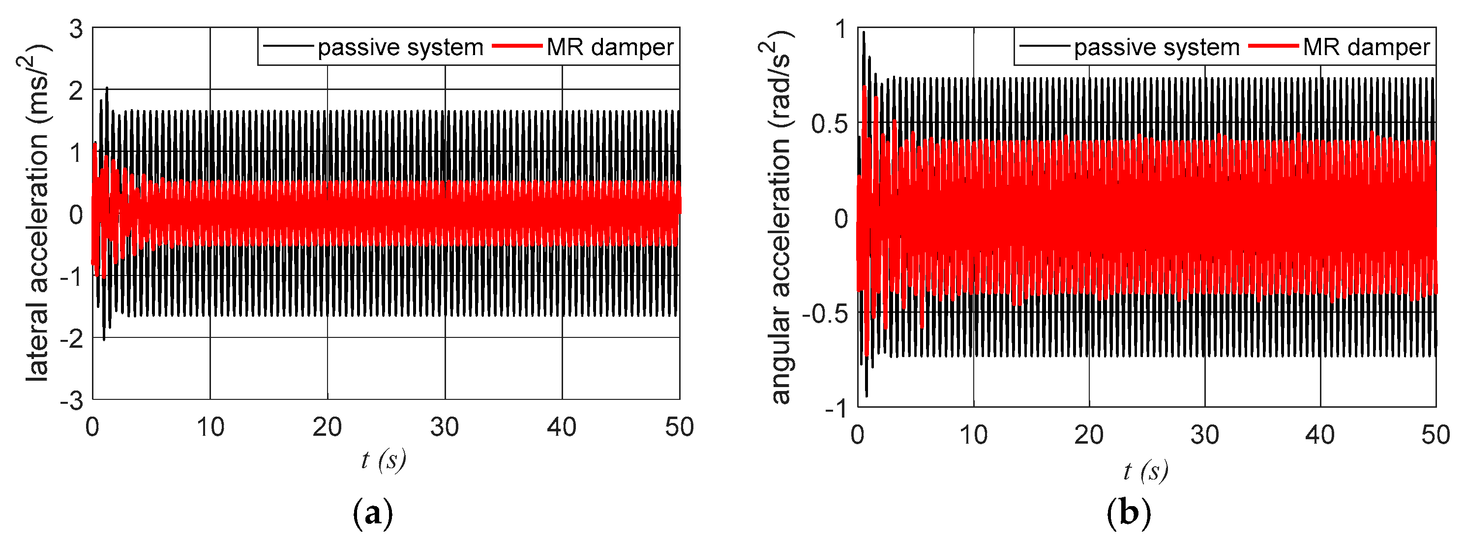
In Figure 11, we can observe the variation in the lateral and angular acceleration of the cabin.
Analyzing the results presented in Figure 11, we can observe that the use of the MR damper also reduced cabin accelerations. In RMS, we have a lateral acceleration of 0.3308 (m/s2), representing a reduction of 72.67% in lateral acceleration. The angular acceleration is 0.3919 (rad/s2), representing a reduction of 35.00% in angular acceleration.
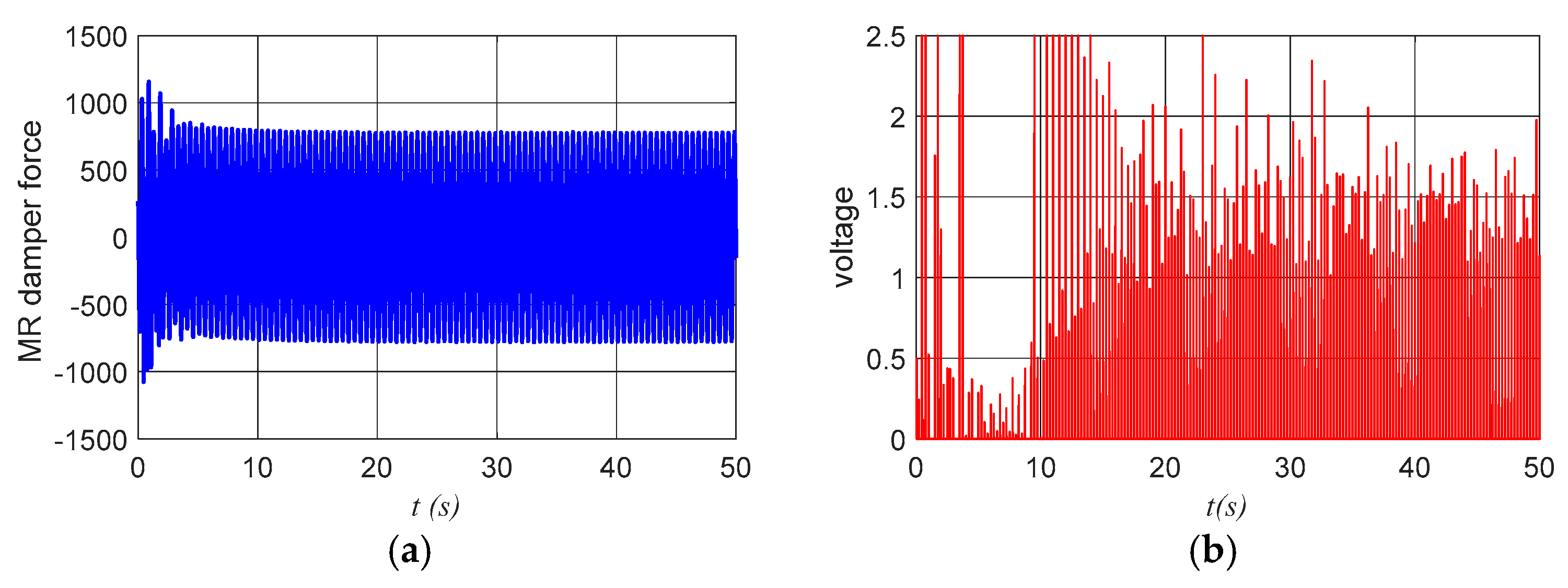
Figure 12 shows the variation in the control signal U and the electrical voltage V (volts).
Analyzing the results presented in Figure 11, we can observe that the control with the MR damper provided a greater reduction in lateral and angular accelerations compared to the active control U shown in Figure 8. Analyzing Equation (7), we can observe that even for zero voltage (V = 0), the damper maintains a damping force, which contributes to the additional reduction in vibration, also reducing acceleration levels when compared with the results of the active system, which did not have the additional damping of the passive MR. The contribution of the U control is in estimating the best force to be applied for the cases V > 0, considering saturation at 2.5 volts ( V max = 2.5 ), the voltage available in [41].

3.4. System Sensitivity in the Case of Parametric Variations

To consider the effect of parameter variations on system dynamics and controller performance, it will be assumed that the parameters can vary by ± 10%, thus including a random variation of 10% in the parameters.
In this work, two situations are considered. The first one considers variations in the following elevator parameters: k1 = 105(0.9 + 0.2r(t)), c1 = 103(0.9 + 0.2r(t)), M = 1600(0.9 + 0.2r(t)), and J = 8090(0.9 + 0.2r(t)). In the second case, variations in the vibration source are considered, with the following parameters: A d = 0.01 ( 0.9 + 0.2 r ( t ) ) and λ = 5 ( 0.9 + 0.2 r ( t ) ) .
Figure 13, Figure 14 and Figure 15 show the lateral and angular variations, force, and electrical voltage for the case of variations only in k1, c1, M, and J.
Figure 14 shows the variation in lateral and angular accelerations.
Figure 15 shows the variation in force and electrical voltage.
Figure 16, Figure 17 and Figure 18 show the lateral and angular variations, force, and electrical voltage for the case of variations only in Ad and λ.
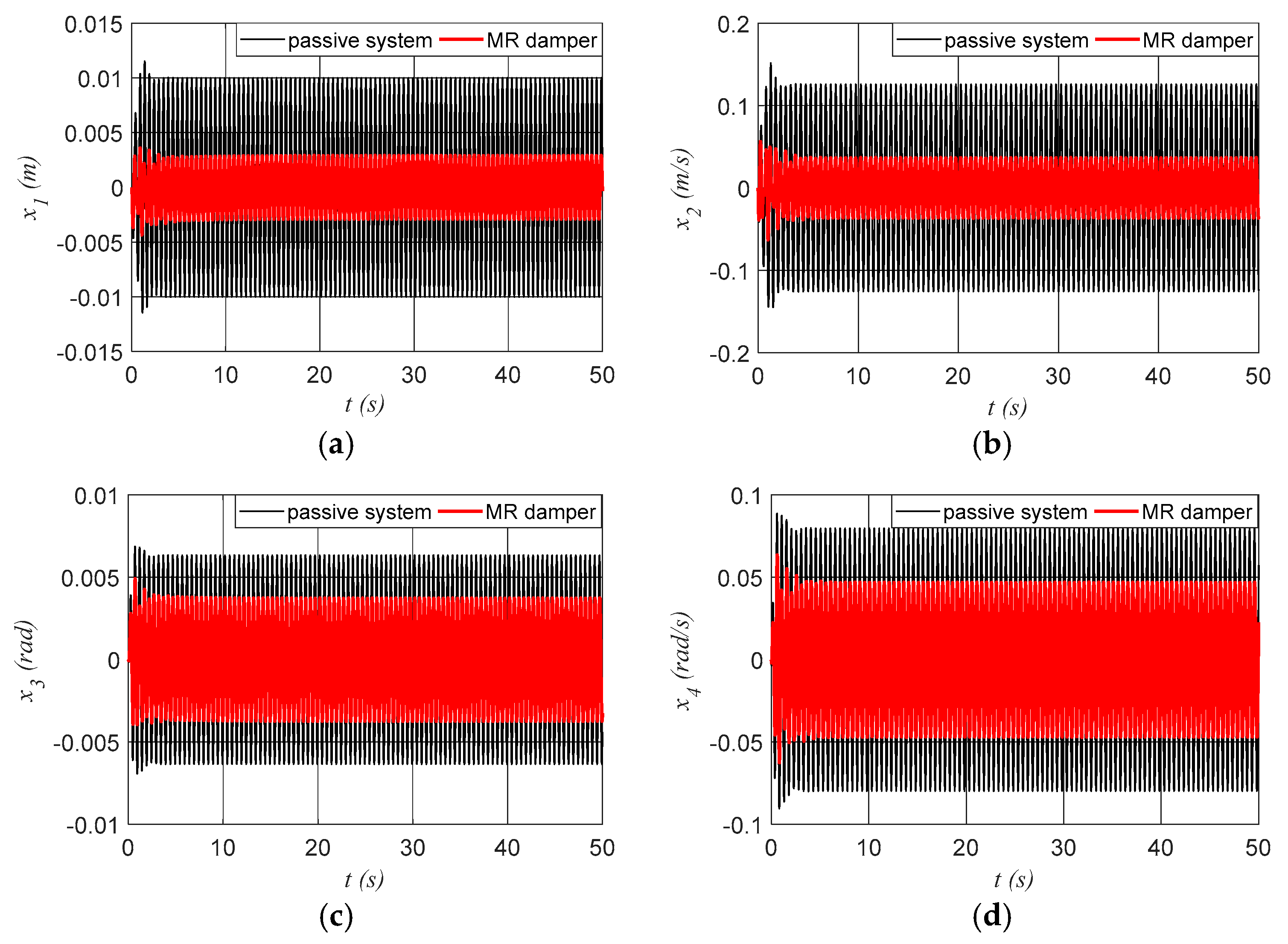
Figure 16 shows the lateral and angular displacements and velocities.
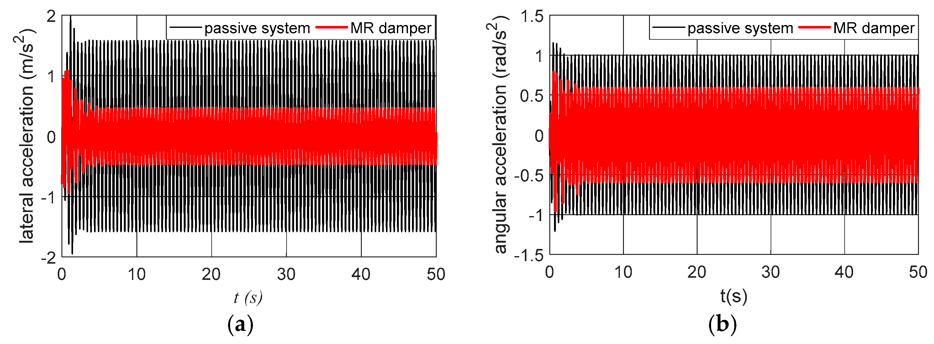
Figure 17 shows the lateral and angular accelerations.
Figure 17 shows the variations in the force of the MR damper and the electrical voltage.
As can be seen in the results presented, both the passive system and the system with control are sensitive to parametric variations for both the elevator parameters and the vibration source.
In Table 1, we present the maximum value of displacement, speed, considering the passive system, for the steady-state system. The accelerations are considered in RMS.
Table 2 presents the maximum value of displacement, velocity, and variation in the MR damper force for the system with the MR damper. Accelerations are also considered in RMS.
An analysis of the data presented in Table 1 and Table 2 shows how sensitive the passive and controlled systems are to parameter variations. We can also observe that the control efficiently reduces the acceleration levels for different parametric variations.

4. Conclusions

In an analysis of the numerical results presented, it is evident that high speed greatly influences vibration levels, thus justifying the application of vibration control systems for high-speed elevators. Regarding the use of the MR damper, its versatility in changing its viscosity by varying the electrical voltage applied to the damper coil is also evident, a feature that allows its use in semi-active vibration control. In an analysis of the results obtained with the proposed control and the results obtained with the passive system, the reduction in lateral and angular acceleration levels is evident. This reduction is related to the increase in the viscosity of the MR damper.
The use of only one MR damper proved to be sufficient to effectively reduce elevator vibration levels at the lowest cost. In continuations of this work, more MR dampers can be included, as well as an optimization analysis to determine the best performance achievable at the lowest cost. Regarding the control strategy using the SDRE control, it was possible to verify that the control is efficient in estimating the necessary forces. However, it was also possible to observe sensitivity to parametric variations, with results encouraging continued research in comparing different control strategies in conjunction with the MR damper.

Author Contributions

Conceptualization, A.M.T., M.G., and G.G.L.; methodology, J.M.B.; software, A.M.T.; validation, A.M.T., G.G.L., and M.E.K.F.; formal analysis, M.G.; investigation, A.M.T. and G.G.L.; writing—original draft preparation, A.M.T. and M.G.; writing—review and editing, M.E.K.F.; visualization, J.M.B.; supervision, A.M.T. All authors have read and agreed to the published version of the manuscript.

Funding

The authors thank the Capes, Fundação Araucária, and CNPq agency. The third author thanks CNPq for the financial support (Process: 309799/2021-0). The fourth author thanks CNPq for the financial support (Process: 304068/2022-5). The last author thanks CNPq for the financial support (Process: 310562/2021-0).

Data Availability Statement

The original contributions presented in this study are included in the article. Further inquiries can be directed to the corresponding author.

Conflicts of Interest

The authors declare no conflicts of interest.

References

  1. Goncalves, M.; Balthazar, J.M.; Oliveira, C.; Fuziki, M.E.K.; Lenzi, G.G.; Tusset, A.M. Active Control System Applied to Vibration Level Control in High-Speed Elevators. Int. J. Robot. Control. Syst. 2022, 2, 581–593. [Google Scholar] [CrossRef]
  2. Qiu, L.; Wang, Z.; Zhang, S.; Zhang, L.; Chen, J. A Vibration-Related Design Parameter Optimization Method for High-Speed Elevator Horizontal Vibration Reduction. Shock Vib. 2020, 2020, 1–20. [Google Scholar] [CrossRef]
  3. Tusset, A.M.; Fuziki, M.E.K.; Lenzi, G.G.; Dos Santos, G.P.; Balthazar, J.M.; Brasil, R.M.L.R.F. Nonlinear Energy Sink Applied in the Vibration Suppression of a High-Speed Elevator System and Energy Harvesting. J. Vib. Eng. Technol. 2023, 11, 2819–2830. [Google Scholar] [CrossRef]
  4. Qiu, L.; Su, G.; Wang, Z.; Zhang, S.; Zhang, L.; Li, H. High-speed elevator car horizontal vibration fluid-solid interaction modeling method. J. Vib. Control 2021, 4, 2984–3000. [Google Scholar] [CrossRef]
  5. Zhang, Q.; Hou, T.; Jing, H.; Zhang, R. Analysis of Longitudinal Vibration Acceleration Based on Continuous Time-Varying Model of High-Speed Elevator Lifting System with Random Parameters. Mech. Ind. 2021, 22, 28. [Google Scholar] [CrossRef]
  6. Wang, N.; Cao, G.; Yan, L.; Wang, L. Modelling and passive control of flexible guiding hoisting system with time-varying length. Math. Comput. Model. Dyn. Syst. 2020, 26, 31–54. [Google Scholar] [CrossRef]
  7. Tusset, A.M.; Santo, D.R.; Balthazar, J.M.; Piccirillo, V.; Dos Santos, L.C.C.; Brasil, R.M.L.R.F. Active Vibration Control of an Elevator System Using Magnetorheological Damper Actuator. Int. J. Nonlinear Dyn. Control. 2017, 1, 114–131. [Google Scholar] [CrossRef]
  8. He, Q.; Jia, T.; Zhang, R.; Liu, L. Adaptive sliding mode control with fuzzy adjustment of switching term based on the Takagi-Sugeno model for horizontal vibration of the high-speed elevator cabin system. Proc. Inst. Mech. Eng. Part C J. Mech. Eng. Sci. 2022, 236, 4503–4519. [Google Scholar] [CrossRef]
  9. Chang, C.-C.; Lin, C.-C.; Su, W.-C.; Huang, Y.-P. H∞ Direct Output Feedback Control of High-Speed Elevator Systems. Seismic Engineering. In Proceedings of the ASME 2011 Pressure Vessels and Piping Conference, Baltimore, MD, USA, 17–21 July 2011; Volume 8, pp. 289–296. [Google Scholar] [CrossRef]
  10. Chen, C.; Zhang, R.; Zhang, Q.; Liu, L. Mixed H2/H∞ guaranteed cost control for high speed elevator active guide shoe with parametric uncertainties. Mech. Ind. 2020, 21, 502. [Google Scholar] [CrossRef]
  11. Crespo, R.S.; Kaczmarczyk, S.; Picton, P.; Su, H. Modelling and simulation of a stationary high-rise elevator system to predict the dynamic interactions between its components. Int. J. Mech. Sci. 2018, 137, 24–45. [Google Scholar] [CrossRef]
  12. Hang, Q.; Yang, Y.; Hou, T.; Zhang, R. Dynamic analysis of high-speed traction elevator and traction car–rope time-varying system. Noise Vib. Worldw. 2019, 50, 37–45. [Google Scholar] [CrossRef]
  13. Tusset, A.M.; Cruz, J.A.; Balthazar, J.M.; Fuziki, M.E.K.; Lenzi, G.G. Nonlinear Control and Numerical Analysis Applied in a Nonlinear Model of Cutting Process Subject to Non-Ideal Excitations. Modelling 2024, 5, 1889–1904. [Google Scholar] [CrossRef]
  14. Kim, K.; Jeon, D. Vibration Suppression in an MR Fluid Damper Suspension System. J. Intell. Mater. Syst. Struct. 1999, 10, 779–786. [Google Scholar] [CrossRef]
  15. Sun, S.; Tang, X.; Yang, J.; Ning, D.; Du, H.; Zhang, S.; Li, W. A New Generation of Magnetorheological Vehicle Suspension System with Tunable Stiffness and Damping Characteristics. IEEE Trans. Industr. Inform. 2019, 15, 4696–4708. [Google Scholar] [CrossRef]
  16. Ata, W.G.; Salem, A.M. Semi-active control of tracked vehicle suspension incorporating magnetorheological dampers. Veh. Syst. Dyn. 2017, 55, 626–647. [Google Scholar] [CrossRef]
  17. Morales, A.L.; Nieto, A.J.; Chicharro, J.M.; Pintado, P. A semi-active vehicle suspension based on pneumatic springs and magnetorheological dampers. J. Vib. Control 2018, 24, 808–821. [Google Scholar] [CrossRef]
  18. Batterbee, D.C.; Sims, N.D.; Stanway, R.; Wolejsza, Z. Magnetorheological landing gear: 1. A design methodology. Smart Mater. Struct. 2007, 16, 2429–2440. [Google Scholar] [CrossRef]
  19. Han, C.; Kim, B.; Choi, S. Design of a New Magnetorheological Damper Based on Passive Oleo-Pneumatic Landing Gear. J. Aircr. 2018, 55, 2510–2520. [Google Scholar] [CrossRef]
  20. Han, C.; Kang, B.; Choi, S.; Tak, J.M.; Hwang, J. Control of Landing Efficiency of an Aircraft Landing Gear System with Magnetorheological Dampers. J. Aircr. 2019, 56, 1980–1986. [Google Scholar] [CrossRef]
  21. Guo, C.; Gong, X.; Zong, L.; Peng, C.; Xuan, S. Twin-tube and bypass-containing magnetorheological damper for use in railway vehicles. Proc. Inst. Mech. Eng. F J. Rapid 2015, 229, 48–57. [Google Scholar] [CrossRef]
  22. Sharma, S.K.; Kumar, A.; Choi, S. Disturbance rejection and force-tracking controller of nonlinear lateral vibrations in passenger rail vehicle using magnetorheological fluid damper. J. Intell. Mater. Syst. Struct. 2018, 29, 279–297. [Google Scholar] [CrossRef]
  23. Sharma, S.K.; Saini, U.; Kumar, A. Semi-active Control to Reduce Lateral Vibration of Passenger Rail Vehicle Using Disturbance Rejection and Continuous State Damper Controllers. J. Vib. Eng. Technol. 2019, 7, 117–129. [Google Scholar] [CrossRef]
  24. Gao, F.; Liu, Y.; Liao, W. Optimal design of a magnetorheological damper used in smart prosthetic knees. Smart Mater. Struct. 2017, 26, 35034. [Google Scholar] [CrossRef]
  25. Christie, M.D.; Sun, S.; Deng, L.; Ning, D.H.; Du, H.; Zhang, S.W.; Li, W.H. A variable resonance magnetorheological-fluid-based pendulum tuned mass damper for seismic vibration suppression. Mech. Syst. Signal. Process. 2019, 116, 530–544. [Google Scholar] [CrossRef]
  26. Aggumus, H.; Cetin, S. Vibration Control of Structures Using Magnetorheological Dampers with H∞ Method. Proc. Int. Struct. Eng. Constr. 2016, 3. [Google Scholar] [CrossRef]
  27. Yang, G. Large-Scale Magnetorheological Fluid Damper for Vibration Mitigation: Modeling, Testing and Control; Department of Civil Engineering and Geological Sciences: Notre Dame, IN, USA, 2001. [Google Scholar]
  28. Vicente, J.; Klingenberg, D.J.; Hidalgo-Alvarez, R. Magnetorheological fluids: A review. Soft Matter. 2011, 7, 3701. [Google Scholar] [CrossRef]
  29. Masa’id, A.; Lenggana, B.W.; Ubaidillah, U.; Susilo, D.D.; Choi, S.-B. A Review on Vibration Control Strategies Using Magnetorheological Materials Actuators: Application Perspective. Actuators 2023, 12, 113. [Google Scholar] [CrossRef]
  30. Lenggana, B.W.; Ubaidillah, U.; Imaduddin, F.; Choi, S.-B.; Purwana, Y.M.; Harjana, H. Review of Magnetorheological Damping Systems on a Seismic Building. Appl. Sci. 2021, 11, 9339. [Google Scholar] [CrossRef]
  31. Samaroo, K.; Awan, A.W.; Islam, S. Semi-Active Suspension Design for an In-Wheel-Motor-Driven Electric Vehicle Using a Dynamic Vibration-Absorbing Structure and PID-Controlled Magnetorheological Damper. Machines 2025, 13, 47. [Google Scholar] [CrossRef]
  32. Choi, Y.T.; Wereley, N.M.; Hiemenz, G.J. Three-Axis Vibration Isolation of a Full-Scale Magnetorheological Seat Suspension. Micromachines 2024, 15, 1417. [Google Scholar] [CrossRef]
  33. Kim, M.; Yoo, S.; Yoon, D.; Jin, C.; Won, S.; Lee, J. Numerical Analysis of the Vehicle Damping Performance of a Magnetorheological Damper with an Additional Flow Energy Path. Appl. Sci. 2024, 14, 10575. [Google Scholar] [CrossRef]
  34. Viadero-Monasterio, F.; Meléndez-Useros, M.; Jiménez-Salas, M.; Boada, B.L. Robust Static Output Feedback Control of a Semi-Active Vehicle Suspension Based on Magnetorheological Dampers. Appl. Sci. 2024, 14, 10336. [Google Scholar] [CrossRef]
  35. Liao, J.; Zhou, F.; Zheng, J. An Improved Parameter Identification Algorithm for the Friction Model of Electro-Hydraulic Servo Systems. Sensors 2023, 23, 2076. [Google Scholar] [CrossRef]
  36. Liu, B.; Yao, H.; Nie, S. Parameter Identification of LuGre Friction Model Based on Interval Analysis. China Mech. Eng. 2013, 24, 2647. [Google Scholar] [CrossRef]
  37. Boston, C.; Weber, F.; Guzella, L. Modeling of disc-type magnetorheological damper. Smart Mater. Struct. 2008, 19, 045005. [Google Scholar] [CrossRef]
  38. Palka, P.; Maślanka, M. Inverse LuGre model for a small-scale MR damper. In Proceedings of the 14th International Carpathian Control Conference (ICCC), Rytro, Poland, 26–29 May 2013; pp. 284–287. [Google Scholar] [CrossRef]
  39. Çimen, T. State-Dependent Riccati Equation (SDRE) Control: A Survey. IFAC Proceedings 2008, 41, 3761–3775. [Google Scholar] [CrossRef]
  40. Su, W.; Jiang, Y.; Yi, C.; Li, S. Lateral Vibration Control Strategy of High-Speed Elevator Car Based on Sparrow Search Optimization Algorithm. Appl. Sci. 2023, 13, 10527. [Google Scholar] [CrossRef]
  41. Sakai, H.C.; Ohmori, H.; Sano, A. Modeling of MR damper with hysteresis for adaptive vibration control. In Proceedings of the 42nd IEEE International Conference on Decision and Control (IEEE Cat. No.03CH37475), Maui, HI, USA, 9–12 December 2003; Volume 4, pp. 3840–3845. [Google Scholar] [CrossRef]
Figure 1. Valve mode.
Magnetism 05 00013 g001
Figure 2. (a) Schematic model of elevator. (b) Equivalent model elevator.
Magnetism 05 00013 g002
Figure 3. Schematic diagram of cabin structure with controlled MR damper.
Magnetism 05 00013 g003
Figure 4. MR damper control system diagram.
Magnetism 05 00013 g004
Figure 5. Acceleration levels in RMS of the elevator cabin for the passive system. (a) Lateral acceleration (m/s2). (b) Angular acceleration (rad/s2).
Magnetism 05 00013 g005
Figure 6. Acceleration levels in RMS of the elevator cabin for the passive system (M = 1600 kg). (a) Lateral acceleration (m/s2). (b) Angular acceleration (rad/s2).
Magnetism 05 00013 g006
Figure 7. Lateral and angular displacement and velocity. (a) Lateral displacement (m). (b) Angular displacement (rad). (c) Lateral velocity (m/s). (d) Angular velocity (rad/s).
Magnetism 05 00013 g007
Figure 8. Lateral and angular acceleration. (a) Lateral acceleration. (b) Angular acceleration.
Magnetism 05 00013 g008
Figure 9. Variations in the control signal U with time.
Magnetism 05 00013 g009
Figure 10. Lateral and angular displacement and velocity for the system with the MR damper. (a) Lateral displacement (m). (b) Angular displacement (rad). (c) Lateral velocity (m/s). (d) Angular velocity (rad/s).
Magnetism 05 00013 g010aMagnetism 05 00013 g010b
Figure 11. Lateral and angular acceleration for the system with the MR damper. (a) Lateral acceleration. (b) Angular acceleration.
Magnetism 05 00013 g011
Figure 12. Variation in the MR damper force with the electrical voltage. (a) Variations in the control signal U. (b) Variation in the electrical voltage.
Magnetism 05 00013 g012
Figure 13. Lateral and angular displacement and velocity for the system with the MR damper, for variations in k1, c1, M, and J. (a) Lateral displacement (m). (b) Angular displacement (rad). (c) Lateral velocity (m/s). (d) Angular velocity (rad/s).
Magnetism 05 00013 g013
Figure 14. Lateral and angular acceleration for the system with the MR damper, for variations in k1, c1, M, and J. (a) Lateral acceleration. (b) Angular acceleration.
Magnetism 05 00013 g014
Figure 15. Variation in the MR damper force with the electrical voltage, for variations in k1, c1, M, and J. (a) Variations in the control signal U. (b) Variation in the electrical voltage.
Magnetism 05 00013 g015
Figure 16. Lateral and angular displacement and velocity for the system with the MR damper for variations in Ad and λ. (a) Lateral displacement (m). (b) Angular displacement (rad). (c) Lateral velocity (m/s). (d) Angular velocity (rad/s).
Magnetism 05 00013 g016
Figure 17. Lateral and angular acceleration for the system with the MR damper for variations in Ad and λ. (a) Lateral acceleration. (b) Angular acceleration.
Magnetism 05 00013 g017
Figure 18. Variation in the MR damper force with the electrical voltage for variations in Ad and λ. (a) Variations in the control signal U. (b) Variation in the electrical voltage.
Magnetism 05 00013 g018
Table 1. Sensitivity of the passive system to parametric variations.
x1 (m)x2 (m/s)x3 (rad)x4 (rad/s)al (m/s2)aa (rad/s2)
without parametric variations0.010840.13640.00620.077991.21060.603
elevator parametric variations0.010.12570.00630.079731.11690.7098
parametric variations in vibration source0.011710.1390.0051920.061631.16840.5201
Table 2. Sensitivity of the controlled system to parametric variations.
x1 (m)x2 (m/s)x3 (rad)x4 (rad/s)al (m/s2)aa (rad/s2) F m r d (N)
without parametric variations0.00280.35690.00340.43750.33080.3919763.1
elevator parametric variations0.00290.036710.00370.046890.33470.4198775.6
parametric variations in vibration source0.0035750.042020.0028280.033390.36530.2860945.2
Disclaimer/Publisher’s Note: The statements, opinions and data contained in all publications are solely those of the individual author(s) and contributor(s) and not of MDPI and/or the editor(s). MDPI and/or the editor(s) disclaim responsibility for any injury to people or property resulting from any ideas, methods, instructions or products referred to in the content.