Article

Process of Fabricating Hyaluronic Acid-Based Milli-to-Microneedles Using the Bi-Directional Drawing Method

1
Department of Semiconductor Electronic Engineering, Daegu Catholic University, Gyeongsan 38430, Republic of Korea
2
Department of Pharmaceutical Engineering, Daegu Catholic University, Gyeongsan 38430, Republic of Korea
*
Author to whom correspondence should be addressed.
Micro 2025, 5(2), 22; https://doi.org/10.3390/micro5020022
Submission received: 1 February 2025 / Revised: 29 March 2025 / Accepted: 18 April 2025 / Published: 1 May 2025

Abstract

:
Microneedles (MNs) have emerged as a promising tool for pain-free drug delivery, offering an alternative to traditional syringe-based methods. Among various types of MNs, dissolving microneedles fabricated from hyaluronic acid (HA) have gained attention due to their biocompatibility and ability to deliver drugs with minimal discomfort. However, conventional HA MN fabrication techniques often limit needle lengths to a few hundred micrometers, which is insufficient for deeper drug penetration. This study introduces a novel fabrication method using bidirectional drawing lithography to extend the length of HA-based MNs. By adjusting the viscosity of HA solutions and employing a controlled pulling process, we demonstrate the feasibility of producing MNs with lengths ranging from millimeters to micrometers. An average height of 15 mm and tip diameters of approximately 80 μm were successfully produced. This advancement enhances the potential of HA MNs for transdermal drug delivery and interstitial fluid sampling.

1. Introduction

Pharmaceutical administration methods can be broadly categorized into two main types: direct drug delivery through the skin and oral medication. Traditional direct drug delivery often involves the use of metal syringes, which can cause significant pain and discomfort. On the other hand, oral administration may not efficiently target specific regions in the body and can place additional strain on the digestive system [1]. To address these limitations, researchers have developed alternative drug delivery systems, with microneedles (MNs) emerging as a promising biomedical solution [1,2,3,4,5,6,7,8,9]. MNs are minimally invasive devices designed to penetrate the skin’s outer layer while avoiding deeper tissues, thereby ensuring a pain-free drug administration experience. Various types of MNs have been developed, including solid [10,11,12], hollow [13,14,15], dissolving [16,17], coated [18,19], and hydrogel-forming MNs [2,4,5,20]. Among these, dissolving MNs fabricated using biocompatible polymers such as hyaluronic acid (HA) have gained considerable attention due to their ability to deliver drugs at precise concentrations with minimal discomfort [8,9]. Recent advancements in MN fabrication have introduced 3D printing techniques, offering improved customization and efficiency [21]. MNs can be manufactured from a variety of materials, each with distinct advantages and limitations [2]. Metal MNs, such as those made from stainless steel and titanium, provide excellent mechanical strength and durability but lack biodegradability and require proper disposal. Silicon MNs allow for high-precision manufacturing but are brittle and prone to fragmentation upon insertion. Polymer-based MNs, including polylactic acid and polyvinylpyrrolidone, offer flexibility and controlled degradation, making them ideal for biomedical applications. Ceramic MNs, such as those constructed from alumina or zirconia, provide high structural integrity and chemical stability. However, the emergence of HA-based MNs has revolutionized transdermal drug delivery due to their superior biocompatibility, hydration properties, and safe biodegradation.
HA-based MNs are particularly promising for transdermal drug delivery and interstitial fluid sampling due to their unique physicochemical properties. HA is a naturally occurring polysaccharide found in human connective tissues and plays a critical role in maintaining skin hydration and elasticity. These MNs dissolve upon application, eliminating the need for needle disposal and minimizing the risk of infection. Additionally, HA promotes wound healing and enhances drug absorption by forming a hydrophilic matrix that facilitates transdermal diffusion. Despite these advantages, conventional HA MN fabrication primarily relies on molding techniques, which produce MNs with lengths limited to a few hundred micrometers [22,23,24]. While this is suitable for cosmetic applications such as facial treatments, developing MNs capable of deeper drug penetration, similar to conventional syringes, remains a challenge. Lee et al. [22] reviewed drawing lithography for microneedles, highlighting fabrication challenges. Surface tension in the liquid state causes capillary self-thinning, resisting elongation, while viscoelasticity in the glass transition state improves drawing stability. In the solid state, structural breakage occurs at the narrowest region, useful for separation techniques. Microneedle manufacturability depends on polymer viscosity, but research mainly focuses on tip sharpness rather than length control. This study introduces a novel fabrication method for adjustable microneedle lengths. Figure 1 illustrates the concept of the bidirectional pulling method to extend the length of HA-based needles, along with the final needle structure ranging from millimeter to micrometer scale in height. Figure 1’s left side depicts a dissolving microneedle formed by dropping HA solution onto a glass slide and pulling it in both upward and downward directions using a rod. The right side shows that after cutting along the cutting line, the needle tip can be made to have lengths ranging from millimeters to micrometers, with the tip’s end diameter being in the tens of micrometers.
In this study, the terms “drawing” and “pulling” will be used interchangeably to convey their intended meaning. The definitions of each term are as follows: Drawing force is the force required to pull and shape a material through a die or forming process. This force enables plastic deformation to achieve a desired shape. Pulling force is an external force applied to move an object in a specific direction. This force is frequently observed in mechanical and structural applications. Surface tension is the force at a liquid’s interface due to molecular cohesion. It minimizes surface area, forming a thin, elastic-like film. This effect allows water droplets to maintain a spherical shape and supports small insects walking on water.

2. Experimental Methods

2.1. Preparation of HA Solution for Dissolving Microneedles

The preparation of an HA solution for dissolving MNs requires careful adjustment of viscosity, mechanical strength, and dissolution rate. HA is generally classified into high-molecular-weight (HMW) and low-molecular-weight (LMW) types. HMW HA (>1000 kDa) contributes to increased viscosity, excellent moisture retention, and strong structural integrity, whereas LMW HA (<500 kDa) enhances skin penetration and modulates mechanical strength [25]. In this study, HA powder (sodium hyaluronate, Contipro a.s., Dolní Dobrouč, Czech Republic) with a molecular weight of 280 kDa was dissolved in deionized water and mixed using a magnetic stirrer. HA solutions with concentrations of 5%, 7%, and 10% were prepared to achieve various viscosities. To eliminate air bubbles generated during the stirring process, the solution underwent a degassing process using a vacuum desiccator.

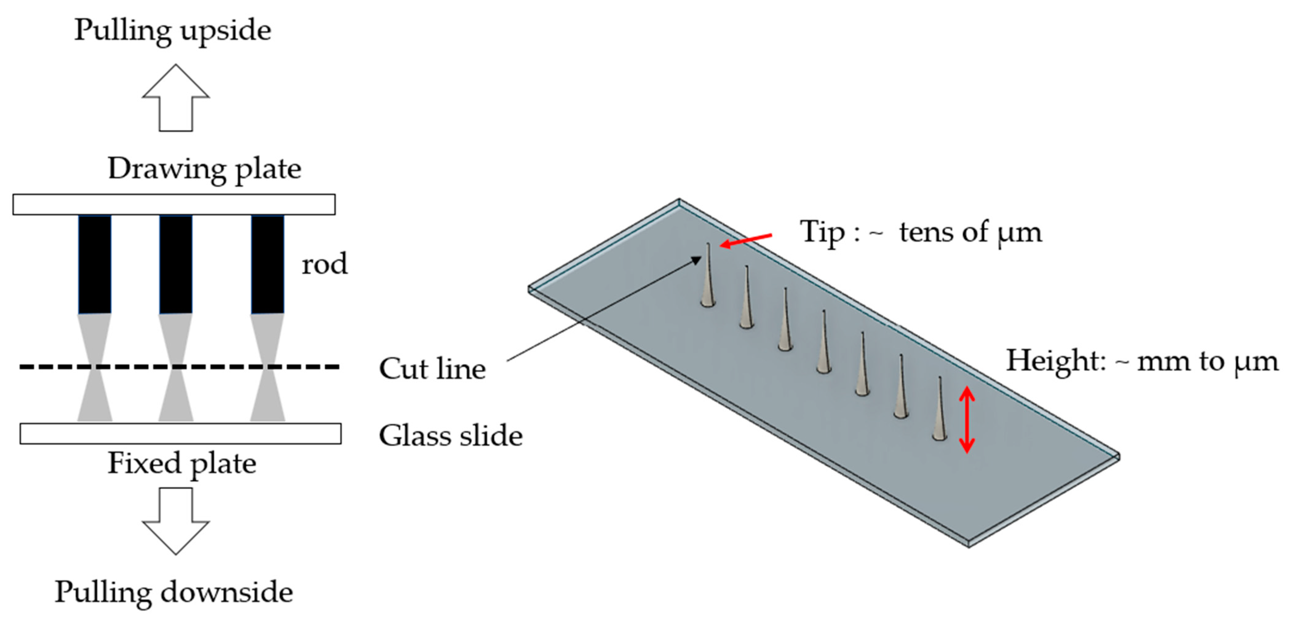
2.2. Design of Drawing Lithography Equipment

In the design of drawing lithography equipment, the primary consideration is how to draw and cure the HA solution. Figure 2 outlines the conceptual design of the process sequence for the stepwise controlled drawing technique for fabricating a dissolving microneedle. Drops of HA in a specified amount are placed at regular intervals on a glass slide (76 × 26 × 1 mm) (Figure 2a). A rod used for drawing lithography is brought into contact with the HA droplets (Figure 2b). Once contact is established, specific distances, delay times, and cycles are set, and the movement is executed automatically (Figure 2c). After reaching the set distance, the viscosity of the HA increases, and curing is performed to harden the HA in contact with the rod. During the curing process (Figure 2d), the viscosity continues to increase, and the HA column maintained between the rod and the glass slide is gradually stretched until it reaches the desired position (Figure 2e). Since the liquid state is maintained after the drawing lithography process is completed, a second curing process is carried out until the material hardens (Figure 2f). Finally, the cutting operation is performed near the required diameter at the tip of the needle to complete the microneedle fabrication (Figure 2g).
Based on the process design for the above drawing lithography procedure, Figure 3 illustrates the drawing lithography equipment. To enhance the precision of the translational distance in the upside and downside directions, a precise lead screw with a lead of 1 mm was utilized. The actuator employed was a Nema17 step motor (Oriental Motor Co., Ltd., Tokyo, Japan), rotating 1.8° per step. The axial translational distance is calculated as follows. Total steps required for one rotation of the step motor: 1 rotation/(rotation angle/step), where 1 rotation = 360°; 360°/1.8° = 200 steps. Since the lead of the screw is 1 mm, the translational distance in the tension direction per step is 1/200 = 0.005 mm. The drawing lithography operation takes place in a sealed space, and during HA curing, the air inside the equipment circulates to dry the extensionally deformed microneedle. The drawing lithography equipment was designed and manufactured in two configurations: the unidirectional movement method and the bidirectional movement method. In the unidirectional movement method, only the upper plate, which holds the rod holder, moves, while the workpiece plate, where the glass slide is fixed, remains stationary. This method is similar to conventional metal tensile testing machines. In contrast, the bidirectional movement method involves both the upper plate (fixing the rod holder) and the workpiece plate moving simultaneously in opposite directions. The top surface of the workpiece is machined to include designated areas for attaching the glass slide, which can be securely held in place through vacuum suction using applied air pressure. The drawing lithography operation is conducted within a sealed space. During the curing process of the HA, the air inside the equipment circulates to facilitate the drying of the elongated, deformed microneedle.
This equipment is programmable, allowing the use of a fan and heater to draw the HA solution and perform curing steps in a repetitive manner. By adjusting the process time, it enables the fabrication of microneedles with the desired size. The process begins with turning on the LED. Next, the heater is activated to regulate the environment, maintaining a temperature of 24 ± 1 °C and a relative humidity of 36 ± 2%. Afterward, the vacuum is turned on during the setting phase. Once the solution is applied, immediate contact is made. The system then performs an automatic stretching process with parameters set to 40/120/30, which takes approximately one hour. Finally, the process enters a waiting phase, lasting between 30 and 90 min.

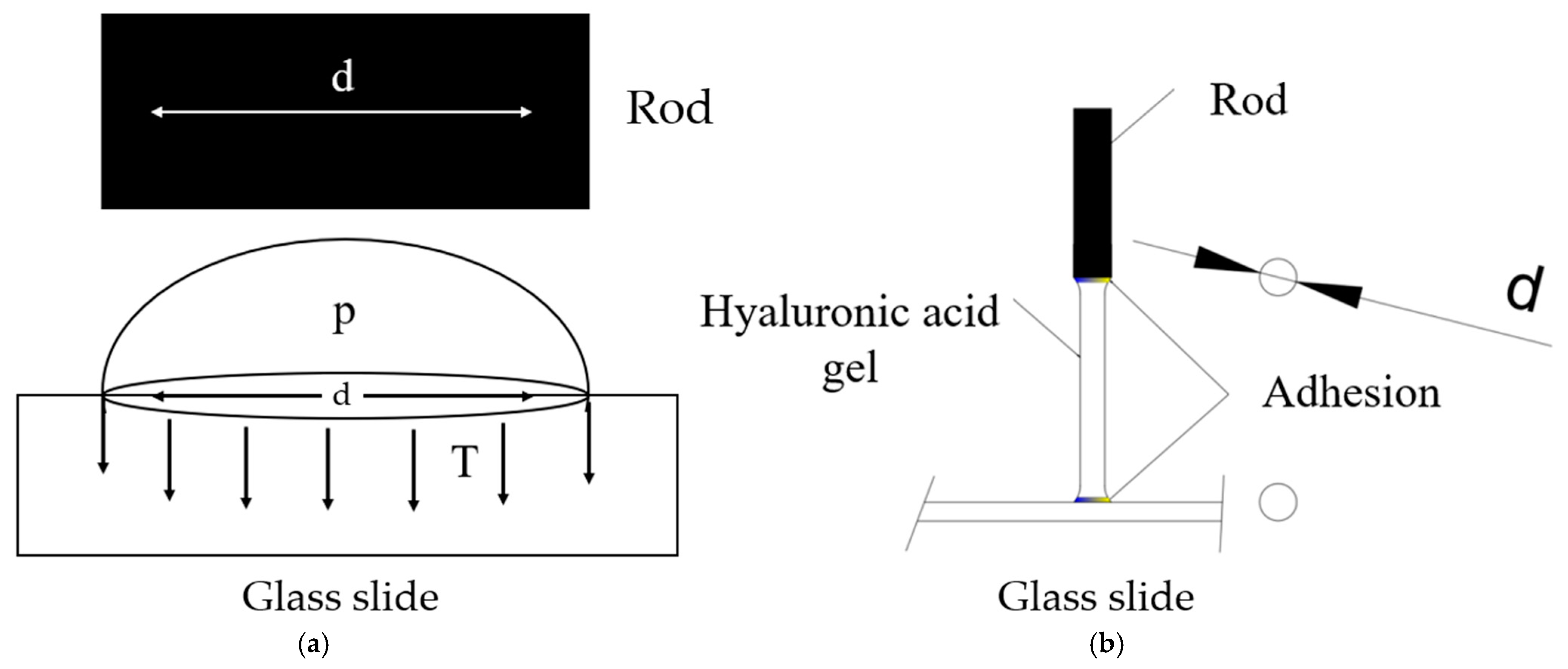
2.3. Mechanical Analysis of Surface Tension

Typically, for drawing testing of solid specimens, adhesion is crucial. However, for fluids (liquids), due to their changing nature and the inability to forcefully adhere them, it is necessary to employ their adhesion characteristics using the surface tension forces of the liquids. Surface tension refers to the property of a liquid’s surface to contract, aiming to have the smallest possible area, resulting in the phenomenon of the liquid forming into a small, rounded shape. In Figure 4, T represents the surface tension of a water droplet, p the pressure difference between the inside and outside of the droplet, and d the diameter of the droplet. The relationship between the forces acting on the cut surface of the droplet, caused by the surface tension, and the force due to the pressure difference can be expressed as follows:
π d T = π d 2 p 4
T = d p 4
Figure 4 represents the most ideal contact. If the diameters of the HA columns formed on the rod and glass slide are the same, it can be assumed that the surface tension of the liquid formed on the rod and glass slide is also the same.
Referring to Equations (1) and (2) for the surface tension of water droplets:
The surface tension on the rod is
T r = π d r p 4
where d r is the rod diameter.
The surface tension on the glass slide side is
T s = π d s p 4
where d s is the liquid diameter on the glass slide.
d p = d s
Therefore,
T r = T s
However, this assumes that gravity is neglected [22].
Under these assumptions, when pulling the liquid, a liquid column with the same diameter is formed, as shown in Figure 4b. However, maintaining a constant diameter of liquid droplets on a flat glass slide is nearly impossible due to the fluidity of the liquid and the influence of gravity. Additionally, maintaining the surface tension of the liquid supported by the rod is challenging due to the weight and liquid characteristics of the liquid.
As depicted in Figure 5, initially, each liquid droplet maintains a spherical shape. However, over time, due to the fluidity of the liquid, the droplets merge, ultimately increasing the surface tension of the entire liquid on the glass slide. As the liquid droplets on the glass slide merge into a single mass, the surface tension of the liquid on the glass slide increases. The surface tension of the liquid on the glass slide is
T s = π D p n 4
where D is the diameter of a water droplet and n is the number of water droplets.
On the other hand, the surface tension of the rod is provided in Equation (3).
Since D d , and
T s T r
Eventually, adhering the liquid to the rod becomes impossible, and due to the fluidity of the liquid, the separation of liquid on the rod increases due to the influence of gravity. To verify this phenomenon, two types of rods were fabricated. The rod applied for tension has a diameter of 2 mm, a length of 15 mm, with a 0.2 mm rod, as shown in Figure 6. Figure 6 shows two cylindrical rods: a straight rod and a grooved rod. Both have a diameter of 2 mm and a minimum length of 15 mm. The straight rod has a uniform shape with no grooves, while the grooved rod features a circular groove near its top. This groove is 0.5 mm from the end, with a width and depth of 0.2 mm, and encircles the rod completely.

3. Results and Discussion

3.1. Liquid Droplet Test

The pulling test involved two types of rods and two concentrations of hyaluronic acid solutions. Before the test, the viscosity of hyaluronic acid solutions at each concentration was measured. The solutions were compressed using a syringe pump, creating droplets at a constant rate. Table 1 shows the physical characteristics of hyaluronic acid solutions with a molecular weight of 280 kDa. The viscosities of the 5%, 7%, and 10% solutions were 4333, 25,330, and 249,700 cp, respectively. The drop falling times for these concentrations were also recorded. Figure 7 shows photos of the HA solution droplet. We measured drop falling time and mass.
Figure 7 analyzed the fluidity of the liquid during the tension of hyaluronic acid solutions, aiming to understand how quickly the solution adhering to the rod could be solidified to inhibit fluidity due to gravity. Concentrations of 7% and 10% exhibit prolonged fluidity even when droplets fall due to the higher viscosity of the solutions. Droplets of the solution do not fall when the surface tension of the liquid is at specific concentrations and weights. While the actual formation of liquid columns during tension may differ somewhat from these drop tests, finding conditions where droplets do not fall due to gravity during tension and utilizing the curing and drying process of the adhesion section is considered possible for various liquid tensions.

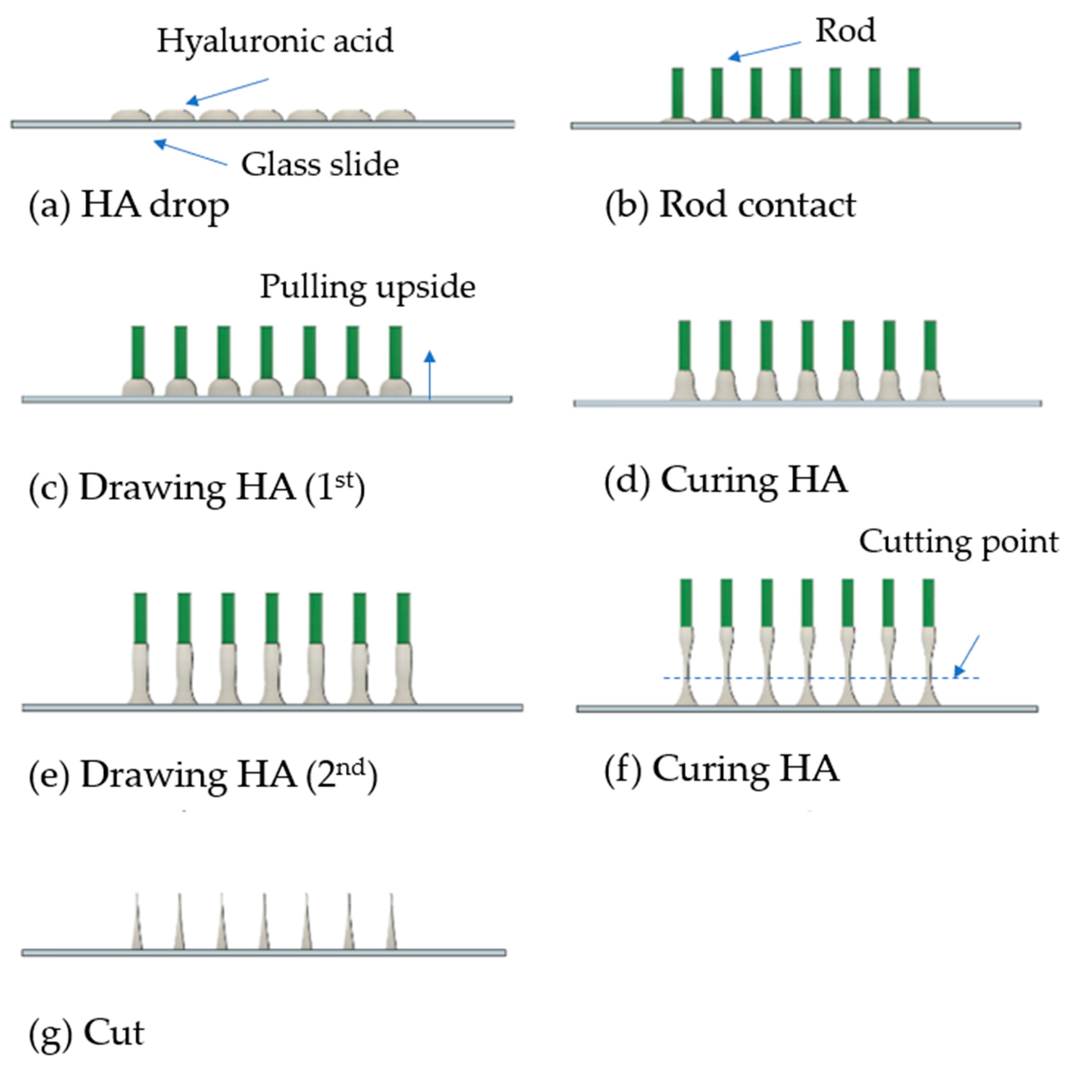
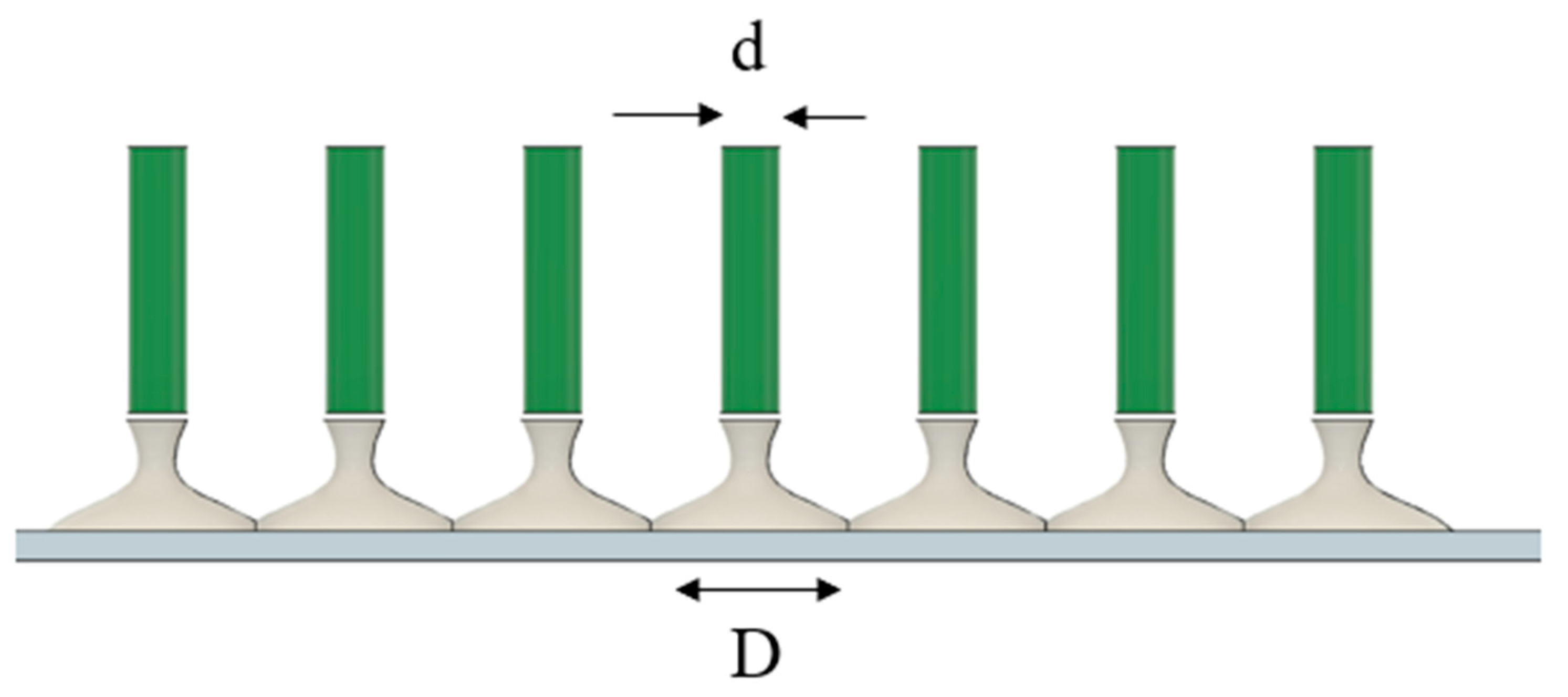
3.2. Unidirectional and Bidirectional Drawing Technique

Unidirectional drawing follows the structure of a drawing machine similar to that shown in Figure 3. In this process, the upper drawing plate moves axially to pull the HA solution, while the lower plate remains fixed. In contrast, bidirectional drawing involves the lower plate moving downward simultaneously with the upper plate to pull the HA solution from both directions. The length of the fabricated microneedle is approximately 11.7 to 17.3 mm, with a diameter of around 0.1 mm at the tip, as shown in Figure 8. The final goal of this research is to create milli-to-microneedles with a length of 10–20 mm. The average length of the formed needle is around 15 mm. As expected, the bidirectional pulling method allows for a greater length compared to the unidirectional pulling method. Additionally, among the 5%, 7%, and 10% HA solutions, the 10% solution resulted in a smoother surface. Comparing the results of pulling force using a straight rod and a grooved rod under the same conditions, the surface states of the results are nearly identical. However, the adhesion of the stepped rod was better than that of the straight rod.
According to the results of the bidirectional pulling test (droplet volume: 2 mL, substrate: 76 × 26 × 1 mm glass slide), the 10% hyaluronic acid solution demonstrated superior adhesion on the glass slide due to its higher viscosity, resulting in higher tensile strength and significant opposing force. However, the elongation and tensile strength per unit area were better for the 7% hyaluronic acid solution. The surface condition of the needle created using the 7% hyaluronic acid solution was smoother than that created using the 10% solution. By appropriately adjusting the pulling and curing time, microneedles with a length of several millimeters were successfully fabricated. Figure 9 shows a millimeter-to-micrometer needle fabricated with a length of approximately 2 mm.

4. Conclusions

In conclusion, this study successfully developed a novel method for fabricating hyaluronic acid-based microneedles with adjustable lengths using bidirectional drawing lithography. The technique overcomes the limitations of conventional methods by allowing for the production of longer MNs, which is crucial for achieving deeper drug penetration. The use of HA solutions with varying viscosities and a controlled drawing process ensures the structural integrity and precision of the MNs. This innovation has significant implications for improving transdermal drug delivery and interstitial fluid sampling, offering a pain-free and efficient alternative to traditional drug administration methods.

Author Contributions

Conceptualization, B.K. and K.L.; methodology, J.-K.K., S.-G.K. and K.L.; formal analysis, B.K. and K.L.; investigation, J.-K.K. and Y.C.; resources, B.K.; data curation, Y.C.; writing—original draft preparation, J.-K.K. and K.L.; writing—review and editing, B.K.; supervision, B.K.; funding acquisition, B.K. All authors have read and agreed to the published version of the manuscript.

Funding

This work was supported by research grants from Daegu Catholic University in 2020.

Institutional Review Board Statement

Not applicable.

Informed Consent Statement

Not applicable.

Data Availability Statement

The datasets used and/or analyzed during the current study are available from the corresponding author on reasonable request.

Conflicts of Interest

The authors declare no conflicts of interest.

References

  1. Kim, Y.-C.; Park, J.-H.; Prausnitz, M.R. Microneedles for drug and vaccine delivery. Adv. Drug Deliv. Rev. 2012, 64, 1547–1568. [Google Scholar] [CrossRef] [PubMed]
  2. Luo, X.; Yang, L.; Cui, Y. Microneedles: Materials, Fabrication, and Biomedical Applications. Biomed. Microdevices 2023, 25, 20. [Google Scholar] [CrossRef] [PubMed]
  3. Aldawood, F.K.; Andar, A.; Desai, S. A Comprehensive Review of Microneedles: Types, Materials, Processes, Characterizations and Applications. Polymers 2021, 13, 2815. [Google Scholar] [CrossRef] [PubMed]
  4. Tariq, N.; Ashraf, M.W.; Tayyaba, S. A Review on Solid Microneedles for Biomedical Applications. J. Pharm. Innov. 2022, 17, 1464–1483. [Google Scholar] [CrossRef]
  5. Saifullah, K.M.; Rad, Z.F. Sampling Dermal Interstitial Fluid Using Microneedles: A Review of Recent Developments in Sampling Methods and Microneedle-Based Biosensors. Adv. Mater. Interfaces 2023, 10, 2201763. [Google Scholar] [CrossRef]
  6. Jung, J.-H.; Jin, S.-G. Microneedle for Transdermal Drug Delivery: Current Trends and Fabrication. J. Pharm. Investig. 2021, 51, 503–517. [Google Scholar] [CrossRef]
  7. Haj-Ahmad, R.; Khan, H.; Arshad, M.S.; Rasekh, M.; Hussain, A.; Walsh, S.; Li, X.; Chang, M.-W.; Ahmad, Z. Microneedle Coating Techniques for Transdermal Drug Delivery. Pharmaceutics 2015, 7, 486–502. [Google Scholar] [CrossRef]
  8. Saha, I.; Rai, V.K. Hyaluronic Acid-Based Microneedle Array: Recent Applications in Drug Delivery and Cosmetology. Carbohydr. Polym. 2021, 267, 11816. [Google Scholar] [CrossRef]
  9. Kang, H.; Zuo, Z.; Lin, R.; Yao, M.; Han, Y.; Han, J. The Most Promising Microneedle Device: Present and Future of Hyaluronic Acid Microneedle Patch. Drug Deliv. 2022, 29, 3087–3110. [Google Scholar] [CrossRef]
  10. Ma, X.; Peng, W.; Su, W.; Yi, Z.; Chen, G.; Chen, X.; Guo, B.; Li, X. Delicate Assembly of Ultrathin Hydroxyapatite Nanobelts with Nanoneedles Directed by Dissolved Cellulose. Inorg. Chem. 2018, 57, 4516–4523. [Google Scholar] [CrossRef]
  11. Li, J.; Liu, B.; Zhou, Y.; Chen, Z.; Jiang, L.; Yuan, W.; Liang, L. Fabrication of a Ti Porous Microneedle Array by Metal Injection Molding for Transdermal Drug Delivery. J. Mater. Sci. 2017, 12, 2. [Google Scholar] [CrossRef] [PubMed]
  12. Ullah, A.; Kim, C.M.; Kim, G.M. Porous Polymer Coatings on Metal Microneedles for Enhanced Drug Delivery. R. Soc. Open Sci. 2018, 5, 171609. [Google Scholar] [CrossRef]
  13. Li, Y.; Zhang, H.; Yang, R.; Laffitte, Y.; Schmill, U.; Hu, W.; Kaddoura, M.; Blondeel, E.J.M.; Cui, B. Fabrication of Sharp Silicon Hollow Microneedles by Deep-Reactive Ion Etching Towards Minimally Invasive Diagnostics. Microelectron. Eng. 2019, 5, 41. [Google Scholar] [CrossRef]
  14. Cárcamo-Martínez, Á.; Mallon, B.; Domínguez-Robles, J.; Vora, L.K.; Anjani, Q.K.; Donnelly, R.F. Hollow microneedles: A perspective in biomedical applications. Int. J. Pharm. 2021, 599, 120455. [Google Scholar] [CrossRef] [PubMed]
  15. He, X.; Sun, J.; Zhuang, J.; Xu, H.; Liu, Y.; Wu, D. Microneedle System for Transdermal Drug and Vaccine Delivery: Devices, Safety, and Prospects. Drug Deliv. Transl. Res. 2019, 17, 1559325819878585. [Google Scholar] [CrossRef] [PubMed]
  16. Ita, K.J.B. Dissolving Microneedles for Transdermal Drug Delivery: Advances and Challenges. Pharmacotherapy 2017, 93, 1116–1127. [Google Scholar] [CrossRef]
  17. Kolli, C.S.; Banga, A.K.J. Characterization of Solid Maltose Microneedles and Their Use for Transdermal Delivery. Pharm. Res. 2008, 25, 104–113. [Google Scholar] [CrossRef]
  18. Chen, X.; Prow, T.W.; Crichton, M.L.; Jenkins, D.W.; Roberts, M.S.; Frazer, I.H.; Fernando, G.J.; Kendall, M.A. Dry-Coated Microprojection Array Patches for Targeted Delivery of Immunotherapeutics to the Skin. J. Control. Release 2009, 139, 212–220. [Google Scholar] [CrossRef]
  19. Chen, J.; Qiu, Y.; Zhang, S.; Yang, G.; Gao, Y. Controllable Coating of Microneedles for Transdermal Drug Delivery. Int. J. Pharm. 2015, 41, 415–422. [Google Scholar] [CrossRef]
  20. Nagarkar, R.; Singh, M.; Nguyen, H.X.; Jonnalagadda, S. A Review of Recent Advances in Microneedle Technology for Transdermal Drug Delivery. J. Drug Deliv. Sci. Technol. 2020, 59, 101923. [Google Scholar] [CrossRef]
  21. Olowe, M.; Parupelli, S.K.; Desai, S. A Review of 3D-Printing of Microneedles. Pharmaceutics 2022, 14, 2693. [Google Scholar] [CrossRef] [PubMed]
  22. Lee, K.; Jung, H. Drawing Lithography for Microneedles: A Review of Fundamentals and Biomedical Applications. Biomaterials 2012, 33, 7309–7326. [Google Scholar] [CrossRef] [PubMed]
  23. Lahiji, S.; Dangol, M.; Jung, H. A Patchless Dissolving Microneedle Delivery System Enabling Rapid and Efficient Transdermal Drug Delivery. Sci. Rep. 2015, 5, 7914. [Google Scholar] [CrossRef] [PubMed]
  24. Song, Y.W.; Nam, J.; Kim, J.; Lee, Y.; Choi, J.; Min, H.S.; Yang, H.; Cho, Y.; Hwang, S.; Son, J.; et al. Hyaluronic Acid-Based Minocycline-Loaded Dissolving Microneedle: Innovation in Local Minocycline Delivery for Periodontitis. Carbohydr. Polym. 2025, 349, 122976. [Google Scholar] [CrossRef]
  25. Miura, S.; Yamagishi, R.; Ando, M.; Hachikubo, Y.; Ibrahim, N.A.; Fadilah, N.I.M.; Maarof, M.; Oshima, M.; Goo, S.L.; Hayashi, H.; et al. Fabrication and Evaluation of Dissolving Hyaluronic Acid Microneedle Patches for Minimally Invasive Transdermal Drug Delivery by Nanoimprinting. Gels 2025, 11, 89. [Google Scholar] [CrossRef]
Figure 1. The concept of bidirectional drawing lithography to extend the length of HA-based microneedles.
Micro 05 00022 g001
Figure 2. Stepwise controlled drawing technique for fabricating a dissolving microneedle. (a) HA drop process, (b) Rod contact with HA solution, (c) 1st drawing HA solution, (d) Curing HA solution, (e) 2nd drawing HA liquid gel, (f) Curing HA liquid gel, (g) Cut HA solid.
Micro 05 00022 g002
Figure 3. Design of drawing lithography equipment (Isometric, Front).
Micro 05 00022 g003
Figure 4. Surface tension of a water droplet before contact between the rod and HA (a) and ideal adhesion in HA (b). Here, T represents the surface tension of the water droplet, p the pressure difference between the inside and outside of the droplet, and d the diameter of both the droplet and the rod.
Micro 05 00022 g004
Figure 5. The real shape due to flow of liquid droplet.
Micro 05 00022 g005
Figure 6. Two types of rods. Here, L denotes the length of the rod.
Micro 05 00022 g006
Figure 7. Photos of HA solution droplets. We measured the drop falling time and mass. The circles highlight the moment just before the droplet falls.
Micro 05 00022 g007
Figure 8. The drawing lithography equipment and millimeter needle.
Micro 05 00022 g008
Figure 9. The fabricated millimeter-to-micrometer needle.
Micro 05 00022 g009
Table 1. Physical characteristics of hyaluronic acid solutions (molecular weight: 280 KDa).
5%7%10%
Viscosity (cp)433325,330249,700
Drop falling time (sec)165959
Drop mass (mg)456
Disclaimer/Publisher’s Note: The statements, opinions and data contained in all publications are solely those of the individual author(s) and contributor(s) and not of MDPI and/or the editor(s). MDPI and/or the editor(s) disclaim responsibility for any injury to people or property resulting from any ideas, methods, instructions or products referred to in the content.

