Article

Active Textile Glove for Cooling and Personal Protection

1
College of Engineering and Applied Sciences, University of Cincinnati, Cincinnati, OH 45221, USA
2
Nanoworld Laboratories, University of Cincinnati, Cincinnati, OH 45221, USA
3
Department of Physics, University of Cincinnati, Cincinnati, OH 45221, USA
4
College of Design, Architecture, Art, and Planning, University of Cincinnati, Cincinnati, OH 45221, USA
*
Author to whom correspondence should be addressed.
Micro 2022, 2(1), 68-87; https://doi.org/10.3390/micro2010004
Submission received: 10 September 2021 / Revised: 1 January 2022 / Accepted: 10 January 2022 / Published: 19 January 2022
(This article belongs to the Section Microscale Materials Science)

Abstract

:
Conventional gloves partially insulate against heat transfer from a hot external environment. They also prevent metabolic heat generated by the human body from escaping. Thus, gloves are a source of heat buildup and heat stress in workers. Heat stress can lead to hyperthermia. Described herein is a glove that cools using a carbon nanotube (CNT) fabric micro-liner and forced convection from a fan. A cold sink is assumed to be located in the glove to cool the convection air. This glove is called an active textile glove. CNT fabric has high thermal conductivity in the plane of the fabric, low thermal conductivity through its thickness, and a large surface area for convection cooling. Thus, the active textile glove can transfer heat from the hand to cooler air in the environment. This paper simulates the performance of a CNT-cooled glove using simple theoretical heat transfer models. Cooling was also demonstrated by testing the glove using a hot plate. Forced convection was found to provide the greatest cooling effect, with it working in synergy with the CNT fabric which aids in spreading heat. CNT fabric also acts as a shield from environmental dangers. The fabric is flame resistant, attenuates radio frequency waves, and prevents smoke particles and toxic chemicals from entering the glove. Testing illustrates the shielding properties of CNT fabric.

1. Introduction

Controlling heat transfer through composite fabric layers is important when it comes to the personal protection of firefighters (FFs), first responders, industrial workers, and other professionals. Modeling can provide an accurate prediction used to verify if a fabric design will be workable under specific situations, especially for novel material applications, such as evaluating carbon nanotube (CNT) fabric. There has been significant prior research on modeling the heat transfer processes in clothing used in high temperature environments. Das et al. [1] performed a theoretical prediction of heat transfer through multi-layer clothing, with a consideration of air gaps in different fabric layers. A mathematical model was developed based on the general equations of heat transfer to generate accurate simulation results, and then appropriate tests were devised to evaluate the method’s validity. Simultaneously, Das et al. evaluated several fabric designs, such as fabric and air layers of various thicknesses, as well as various combinations, to determine the most successful designs. Guan et al. [2] investigated the transfer of water in a human clothing system when the human body perspires constantly in a radiation heat environment. Understanding the research of Guan et al. on the mass transfer generated by human body perspiration in the clothing system is crucial when it comes to simulating clothing thermal protection and thermal physiology. Many earlier studies looked at specific moisture transfer methods and specifics in clothing, but they did not take into account the impact of liquid sweating or the external high-temperature environment. The Guan et al. investigation included two crucial factors: ambient heat and human sweating. A multi-stage experiment using a sweating trunk as the experimental object was devised. Guan et al. found that as the sweating rate increased, so did the evaporation rate of the sweating trunk in garments. This research is useful when it comes to better understanding the process of continuous sweat transfer and evaporation in clothing, as well as the thermal physiological burden faced by FF and other first responders working in high-temperature environments. Modeling thermal protection provided by clothing was an important advance in the work. Additionally, Prasad et al. [3] examined the thermal properties of FF protective clothing. Their research began with a numerical investigation of transient heat transfer and water vapor transport. Prasad et al. [3] developed a mathematical model for the transient heat and moisture transfer of multilayer fabrics, taking into account both the presence and absence of air gaps between three layers of FF protective clothing. The simulation results indicated that when heated, the water in the fabric easily evaporates, and a portion of the evaporated water condenses back into the fabric. Additionally, the temperature within the fabric layer and the total heat flux transmitted to the human skin are inseparably linked to the moisture distribution within the protective garment. Simultaneously, Prasad et al. conducted corresponding experiments and compared them to the simulation results.
Although considerable research has been conducted on heat transfer processes and sweat evaporation through fabric, all these experiments and simulations have used commercially available clothing materials such as cotton, nylon, polyester, and with specialty finishes applied to those materials, and so on. Sullivan et al. [4] proposed a garment cooling system in 2015 based on CNT fabric for FFs. The work proposed a type of specialized clothing that incorporates a CNT sheet into the FFs’ clothing and connected the CNT sheet to a cold sink, which effectively lowered the FFs’ skin temperature. By developing a finite element model for simulation analysis, the cooling system could be designed to protect the FF and reduce skin temperature. Heat transfer theory and information on CNT materials is available [5,6,7,8].
Indeed, the importance of a cooling system is underscored by the fact that, according to [9,10], about 100 FFs died on-duty in the United States in 2020. About one third of the FFs listed by the US Fire Administration (USFA) died due to the COVID-19 virus. Roughly one-third died possibly due to heat-related complications such as heart attacks, burns, and vascular problems. About one-third died due to accidents and other reasons. While FFs must work in harsh environments, their clothing is made of Kevlar/Nomex materials that were developed 50 years ago to insulate a large amount of radiant heat from the environment. However, these materials not only block heat from the outside, but also insulate a significant amount of metabolic heat generated by the body within the clothing, further complicating the already multi-faceted issues of the environments in which FFs must operate. For the first time, Sullivan et al. proposed to incorporate a CNT sheet into FF protective clothing. After exposure to heat flow, the average skin temperature of the model with the CNT layer and cold reservoir was found to be 6 °C lower than that of the model without the CNT layer and cold reservoir based on a finite element simulation. In contrast to that study and other researchers’ work, this current paper [11] develops simple heat transfer models for CNT materials used in FF protective clothing [12]. Also, Sullivan et al. used ice as the primary material for a cold sink to absorb most of the heat generated by the body and the surrounding environment. However, ice significantly increases the FF’s weight load and the metabolic heat generated within the FF’s body. Additionally, when ice absorbs sufficient heat, it melts, significantly reducing the efficiency of subsequent heat absorption. Furthermore, Sullivan et al. did not consider the effect of sweat on body heat dissipation and airflow throughout the fabric [4].
In another work [13], Elgafy et al. developed a heat transfer model for carbon foam materials to be used in FF uniforms. Although the heat transfer model was primarily concerned with the thermal protection performance of carbon foam fabric, a comprehensive heat conduction model of FF-specific apparel was constructed in a systematic manner, which is the same as the central issue presented in the current paper. Ahmed Elgafy et al. investigated and optimized the thickness, thermal conductivity, porosity, and density of carbon foam fabric for FF apparel design. The developed heat conduction model was two-dimensional, similar to the design model presented in this paper. However, Elgafy et al. simulated heat conduction using ANSYS Fluent CFD software, while our study employed MATLAB and standard heat transfer formulas. Carbon foam fabric has low thermal conductivity in all directions, and low density. CNT fabric has low thermal conductivity through the thickness and high thermal conductivity in the plane of the fabric, and low density. Elgafy et al. focused on reducing the weight of FF apparel while maintaining a specific level of heat insulation performance. Since carbon foam fabric is unable to remove significant amounts of heat from the garment system, FFs can only operate in high temperature environments for a limited period of time. In comparison, the CNT fabric FF glove proposed can isolate a significant amount of heat from the environment while actively removing heat, including metabolic heat, by forced convection.
Onofrei et al. [14] examined heat transfer via multilayer protective clothing when subjected to modest levels of thermal radiation. They created a mathematical model of heat transfer in protective clothing exposed to a low degree of radiant heat flow in a typical fire environment. The mathematical model was based on the finite element approach and was produced using the COMSOL Multiphysics tool. The computational results showed the temperature variation at the protective garment system’s inner face over time when exposed to a low-radiant heat flux and during the cooling-down phase. Simultaneously, the model predicted first- and second-degree burns by merging a heat transmission model through a multilayer protective system with a skin heat transfer model. Even at modest levels of thermal radiant heat flux, the results suggested that a standard three-layer thermal protective garment system is required to protect the user from skin burn injury. Onofrei et al. also investigated heat transfer via protective garments in response to temporal variations. In comparison, the current article’s simulation model focuses only on the steady-state temperature distribution across a CNT fabric FF glove garment. This model takes into account the thickness, convective area, air movement, and moisture content of human sweat simultaneously, providing more information and realistic simulation results.
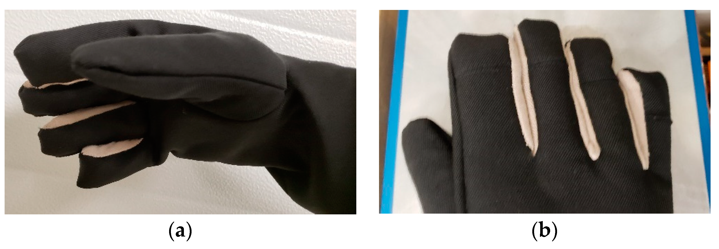
This paper [11] considers CNT fabric material that, unlike conventional materials, is a thermal insulator through its thickness but is a thermal conductor in-plane. Thermal conductivity in-plane can be used to distribute heat, thereby reducing hot spots on clothing, and increase sweat evaporation as heat and moisture are wicked across the surface. To investigate directional thermal conductivity, this paper relies on simulations and preliminary experiments involving the layering of conventional fabrics with CNT fabric. Additionally, particles such as granulated activated carbon (GAC) can be incorporated into the CNT fabric to improve certain properties such as thermal conductivity or breathability. Carbon hybrid materials (CHM) are defined here as conventional fabric materials constructed (layered) with CNT fabric materials that may contain enhancing particles. Essentially, CHM is a composite of CNT fabric, with optional nanoparticles inside, and conventional fabrics that can be used to design industrial personal protective equipment (PPE). Personal protective gloves made with CHM can aid in the cooling process and reduce heat stress on the FF. Simultaneously, the CHM material may prevent toxic gases and particles from penetrating through the fabric, which prevents contact with cancer-causing materials. In this paper, a glove incorporating CNT fabric is designed. The optimal design of the glove depends on specific environmental and material variables. This type of modeling is not fully developed. Thus, this paper develops a simple model of an active textile glove for personal protection to investigate the heat spreading of CHM and heat transfer through a glove. In this case, the main heat source comes from the environment. A primary cause of death for FFs is increased body stress and heart attacks caused by metabolic overheating. In terms of clothing design and FF equipment, a primary contributor to this problem is the excessively heavy and highly insulated turnout gear. Using heavy protective equipment in extreme conditions causes the FF’s body to generate additional metabolic heat. To compound the issue, the turnout fabric system’s insulating and adiabatic properties can trap significant amounts of metabolic heat, aggravating the situation for FFs. In such a scenario, the application of CHM fabric may reduce the weight of the clothing, thereby achieving the benefit of reducing the metabolic heat generated by the FF. Reduced the thickness and weight of the fabric also alleviates extra bulk, and provides added dexterity, flexibility, and range of motion for the FF while wearing the gear. This can lead to increased comfort and improved dexterity, which may reduce the risk for injury in service.
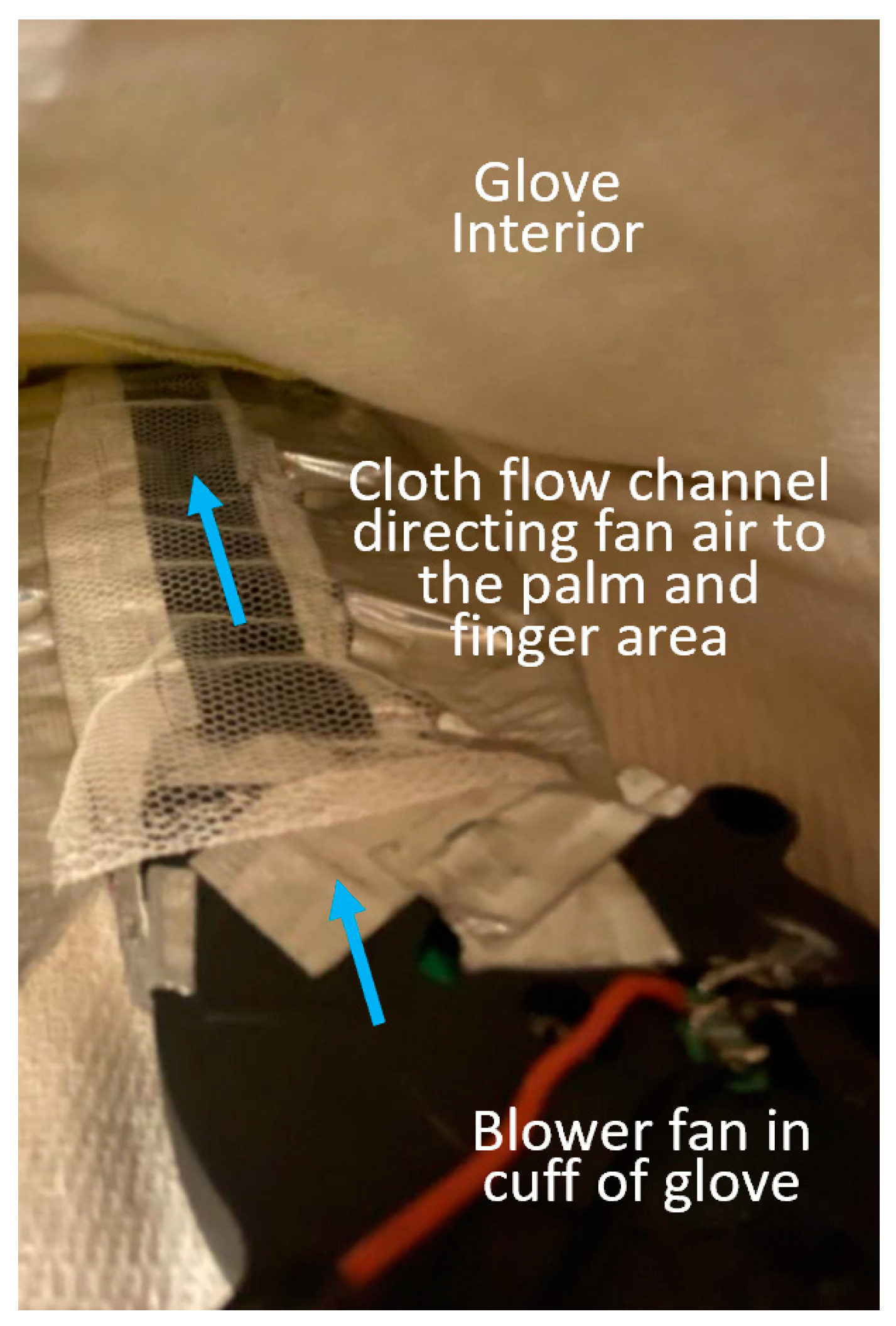
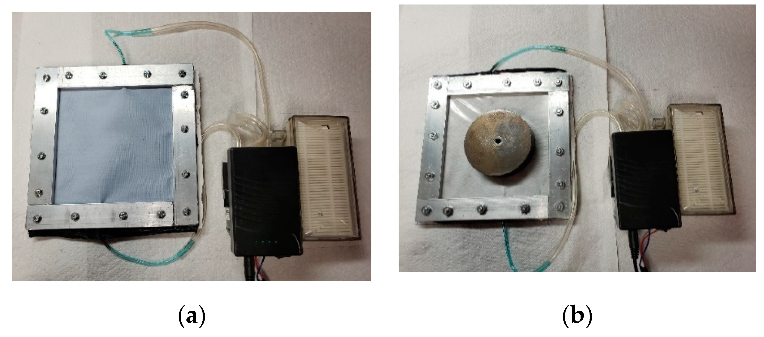
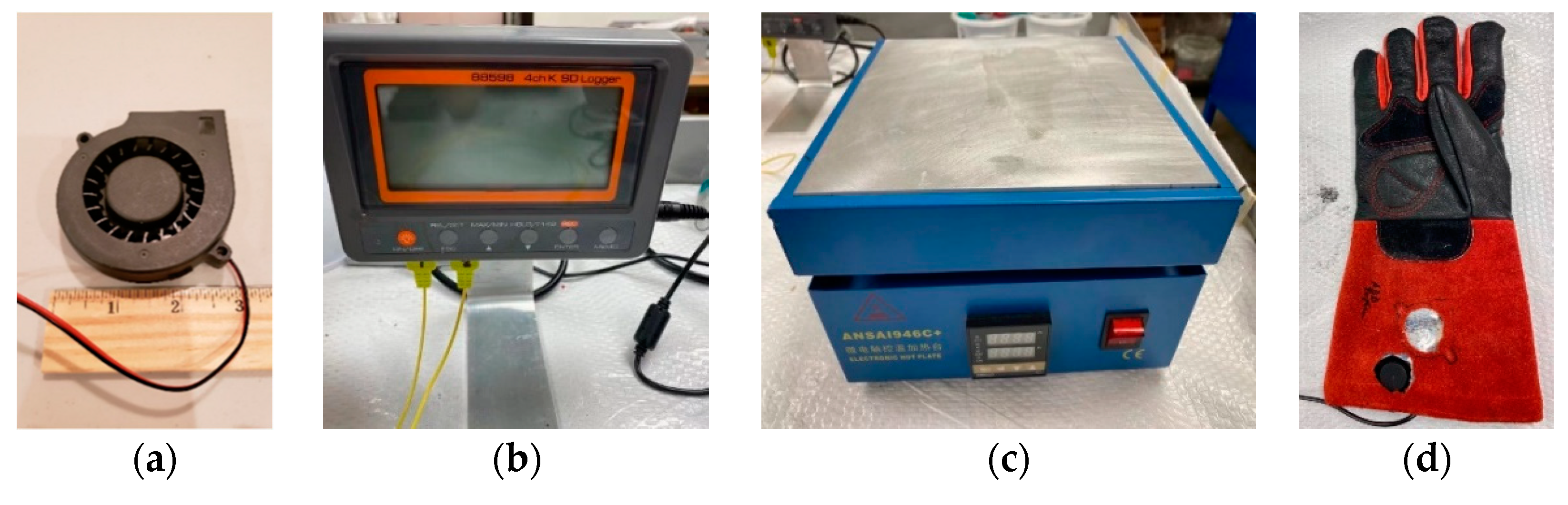
A glove was considered for this initial study because the amount of CNT fabric needed is less than in larger garments such as coats or pants. Conductive and convective heat transfer were emphasized in the construction of the FF glove simulation model. This model simulates the heat transfer process through the CHM fabric layers of an FF glove, which includes heat sources through two sides of the glove from the external working environment (the hand and glove both have two sides). Metabolic heat generated by the human body and the evaporation processes were not included in this model. The model only considers the heat from the external work environment because the metabolic heat generated by the hand is small in comparison to the external heat of the conditions simulated. Simultaneously, a prototype FF glove with CHM fabric and a cooling fan was constructed. Preliminary thermal testing was carried out to support the model simulation results and design feasibility. In this case, natural convection was compared to forced convection, indicating that air flow is very important in FF apparel design. The simulation enabled an examination of the sensitivity of design parameters and the extent to which CHM fabric can aid in the protection of FFs. Textiles with forced cooling and thermally conductive fabric provide enhanced protection compared to conventional fabric and are called active textiles.

2. Materials and Methods

2.1. Theoretical Background for Heat Transfer

The active textile gloves were designed on the basis of heat transfer theory, which includes thermal convection, thermal conduction, and thermal radiation. However, only thermal convection and thermal conduction are explicitly modeled in the simulation model. The reason for this is that thermal radiation is complicated to model in clothing design, and its effect is context dependent. The simulation model of the active textile gloves enables the basic examination of the CNT sheet’s general thermal properties and application scenarios. As a result, this model effectively simplifies the heat transfer model by specifically considering thermal convection and thermal conduction. Within the thermal conduction model, the simplification includes heat transfer via heat radiation. Thermal radiation is approximately combined with thermal conduction and enters the next layer of materials in this simplified model, which eliminates the need for thermal radiation equations to be programmed in the numerical model.
The first law of thermodynamics for a closed system can be explained in Equation (1), where Q is the heat transfer rate (Watts), W is the work rate (Watts), U is the rate of change of internal thermal energy (J) in the system, and t is time (s) [5].
Q = W + d U d t
Heat flows through a solid by a process called thermal diffusion, or simply diffusion or conduction [6] (p. 87). Fourier’s law of conduction is explained in Equation (2):
q k = k A d T d x
where q k is the rate of heat transfer by thermal conduction (Watts), k is the thermal conductivity (W/mK), T ( x ) is the local temperature (K), x is the distance in the direction of the heat flow (m), and A is the area through which heat is transferred (m2) [6] (p. 10). In Equation (2), heat flows from higher to lower temperature areas by the second law of thermodynamics. The rate of heat transfer by convection between a surface and a fluid is given by Equation (3):
q c = h c ¯ A Δ T
where q c represents the rate of heat transfer by convection (W), A represents the area of heat transfer (m2), ΔT represents the temperature difference between the surface temperature and temperature of the fluid (K), and h c ¯   represents the average convection heat transfer coefficient over the area, A (W/m2K) [6] (p. 21). At the same time, there are several significant parameters in thermal convection theory. First, the boundary layer should be considered. The viscous force is dependent on the shear stress, τ, as shown in Equation (4) [6] (p. 288).
τ = μ d u d y
Here, μ is the dynamic viscosity (Ns/m2), and du/dy is the velocity gradient. The unit for the velocity gradient is s−1. Thus, based on this definition, the boundary layer is the area where the velocity of the fluid decreases due to the viscous forces. The dimensionless Reynolds number (Rex, Equation (5)) determines if the fluid flow is laminar flow or turbulent.
R e x = ρ U x μ = U x v
In Equation (5), U is the free-stream velocity (m/s), x is the distance from the leading edge (m), v is the kinematic viscosity (m2/s) of the fluid flow, and ρ is the density of the fluid (kg/m3) [6] (p. 288).
The evaporation of sweat (considered to be small for a low work activity example case) and metabolic heat generated by the hand (considered to be small in comparison to the external heat in the model) have been excluded from the glove simulation model. This simulation model is concerned with thermal conduction and convection, as well as the modeling of the CNT sheet within the glove. Another critical parameter in convective heat transfer is air flow. Between the layers of the glove is an air gap that allows for air exchange while the glove is being worn. The cooled glove design incorporates a small blower fan that circulates air between the glove’s layers, generating airflow when the glove is in heavy use (when the hand temperature exceeds a set value). Forced convection heat transfer is modeled using the air flow within the fabric layers.

2.2. Carbon Nanotube Fabric

The properties of CNTs have been extensively studied over the last two decades, including their mechanical, electrical, and thermal properties. CNT yarn and sheet manufactured using the floating catalyst method exhibit acceptable mechanical properties [7]. The combined flexibility, electrical and thermal conductivity, low density, and flame resistance of CNTs are unmatched by any other fiber or sheet on the market [7]. The superior properties are due to van der Waals forces forming bundles of CNTs and the entanglement between bundles, akin to nonwoven fabric constructions. The tensile strength of this type of CNT fabric is approximately 0.4 GPa and is highly correlated with gauge length [7]. The electrical conductivity of CNT fabric produced by the floating catalyst method is about 1 × 10⁴ S cm−1 However, the electrical conductivity of CNTs can be increased by adding nanoparticles to the material during the synthesis process [7]. As a result of CNT materials’ good electrical properties (good electrical and thermal conductivity, high maximum current density, light weight, and non-corrosive behavior), a wide variety of products related to electrical conductivity and electromagnetic shielding can be designed using them.
The thermal properties of CNT fabric determined the design of the active textile glove. However, due to a dearth of research in this area, the thermal properties of CNT fabric and yarn materials synthesized via the floating catalyst method were not significantly studied or optimized [7]. The thermal properties of CNT fabric have been inconsistently reported due to a variety of measurement techniques and different processes associated with manufacturing the material. The experimental thermal conductivity of CNT yarn is 770 ± 10 W (m K)−1 according to the research done by Gspann et al. [7]. The thermal conductivity of CNT fabric in-plane is estimated to be in the order of 100 W (m K)−1 and in the order of 1 W (m K)−1 transverse to the plane. For reference, the room temperature thermal conductivity of aluminum is 237 W (m K)−1, and copper is 401 W (m K)−1. The thermal conductivity of CNT fabric also varies greatly depending on the density of the material. The anisotropy in thermal conductivity between in-plane and through the thickness directions can differ by a factor of 100. Another recent paper examined the convective heat transfer properties of CNT sheets. Jiang et al. [8] determined the natural convective heat transfer coefficient of a CNT sheet to be 69 W (m2 K)−1, which is greater than that of aluminum foil in the same measurement environment [8].
A CNT sheet with a thickness in the tens or hundreds of microns range has a high thermal conductivity in-plane and a large convective heat transfer coefficient. The horizontal and vertical heat transfer conduction coefficients of CNT sheets can be taken advantage of in garment design. CNT sheets have a high value of thermal conductivity in-plane which is appropriate for spreading heat; and a low value in the transverse direction (through the thickness), which is appropriate for insulating heat. We believe the difference between the thermal conductivity of CNT fabric in-plane versus through-the-thickness is due to the fact that the through-the-thickness direction has a greater number of nanotube–nanotube interfaces compared to the in-plane direction. CNTs produced by the floating catalyst method are approximately 1 mm in length and a few nm in diameter. A sock of CNT (microscopically a web of nanotube bundles) is formed in the synthesis process. Individual CNTs bundle together to form strands of approximately ten nanotubes. The strands agglomerate together in the synthesis process in the reactor in a random orientation. The sock or web of nanotube bundles exits the reactor tube and is wrapped layer by layer onto a rotating drum to form a planar sheet or fabric. There is a nanotube-to-nanotube end to end interface or junction about every 1 mm (106 nm) in the plane of the fabric. The junctions are a source of thermal resistance, and their total number should be kept to a minimum. Nanotube to nanotube junctions occur approximately every 3 nm in the through the thickness direction. As a result, there are significantly more junctions in the through the thickness direction than the in-plane direction. Thus, the thermal conductivity, and the electrical conductivity, in the through the thickness direction is significantly lower than in the in-plane direction. This directional thermal conductivity property can be used to design active textile garments because the CNT sheet can reduce heat transfer into the human body and assist the convection process inside the garment and glove, making it an excellent material for improving the comfort of FF on the scene of a fire and reducing the risk of injury. Thermal conduction depends on the material’s surface area and thickness, not just on its thermal conductivity coefficient. Thus, heat conduction must be determined by the specific fabric design, the coefficient of thermal conduction, the area and thickness of the fabric material, and the temperature difference across the fabric. To fully understand the behavior of CNT fabric in FF apparel, a heat transfer model is needed.

2.3. Glove Heat Transfer Model Construction

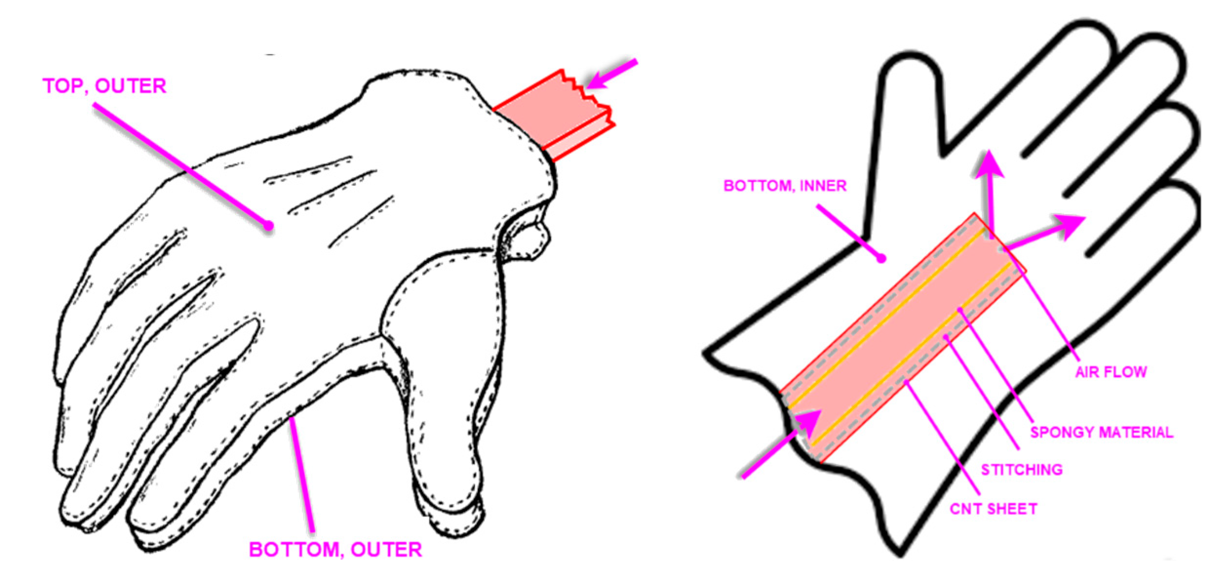
A MATLAB simulation model of the active textile protective glove that could be worn by FF and welders was built using the heat transfer equations introduced in the theoretical background. The model is focused on convective and conductive heat transfer through the glove’s various fabric layers. According to heat transfer theory, the simulation model includes an air flow component; as air flow increases, convective heat is transferred. The simulation model of the glove, based on a realistic glove design, takes into account the two-sided (top and bottom surfaces of the glove) heat input from the environment. The simulation model has two components: a heat transfer model and a glove model. In the heat transfer model, the hand is connected to the arm. The glove model, meanwhile, contains two fabric layers. The outer layer of the glove is made of thermal insulating material and the second layer is a CNT sheet layer. The CNT layer aids in convective heat transfer. The low thermal conductivity of CNT material through its thickness allows the glove to also act as a thermal insulation material, which reduces the amount of heat entering the glove from the environment. The most critical aspect of the glove design is modeling the CNT fabric. In the model, the two-layer fabric system is in contact with the surface of the hand.
In the convection and conduction model, heat from the environment is transferred into the garment and then through the CNT sheet to the hands. The temperature in a FF’s working environment may temporarily reach to 100 °C when the glove is in contact with a hot object. However, the safe operating temperature for humans is approximately 40 °C. Understanding the convective and conductive heat transfer will assist in lowering the temperature to a level that is safe for FFs. 
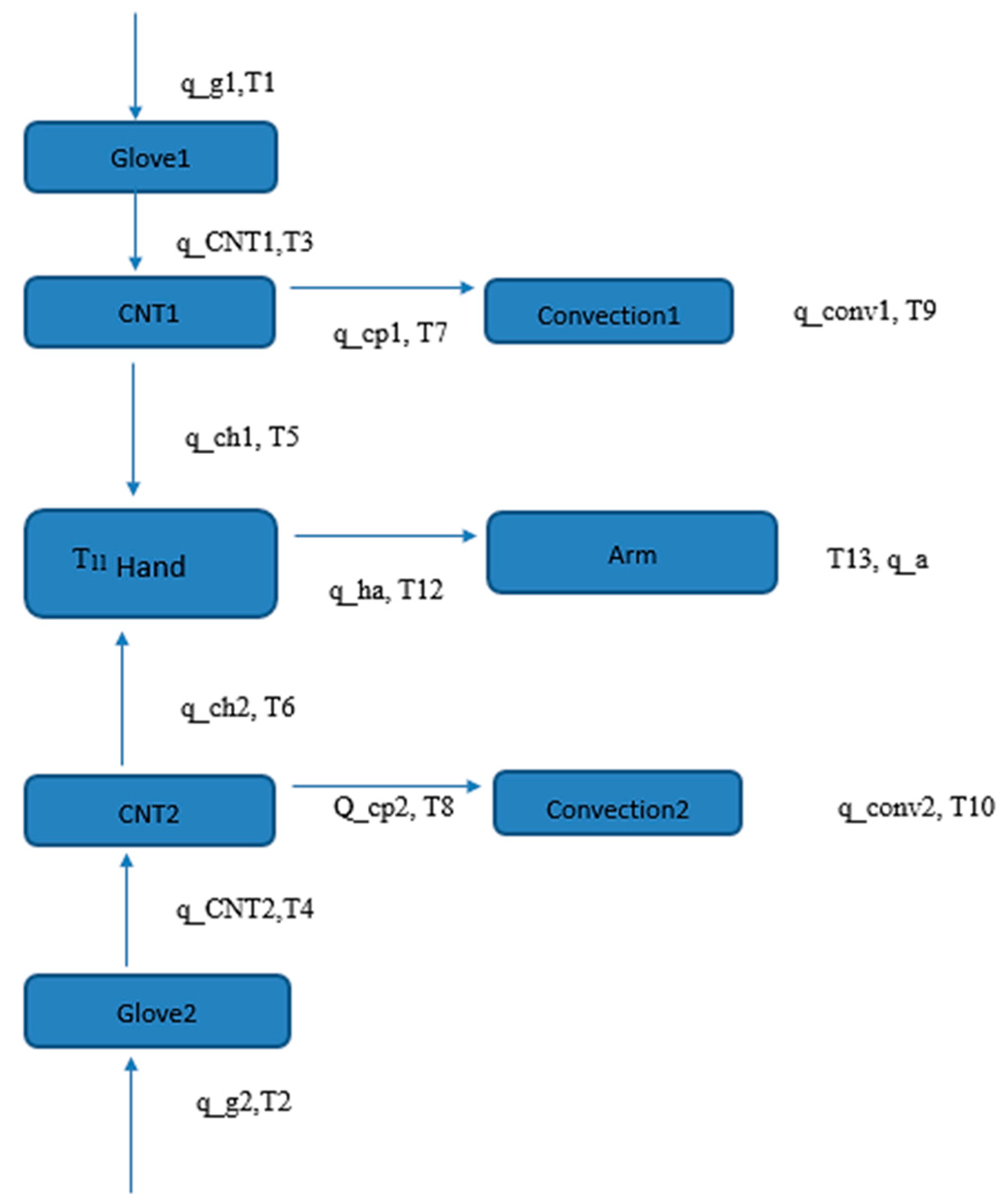
Figure 1 illustrates the theoretical model of a glove created in MATLAB.
In the glove system, the hand and arm are linked. The blue boxes here represent various components of the numerical simulation model. Glove 1 refers to the glove’s upper-side outermost layer. Glove 2 is the down-side outermost layer of the glove. CNT 1 is a CNT sheet layer that contacts the palm of the hand. CNT 2 is a CNT sheet layer that contacts the back of the hand. Convection 1 and convection 2 represent the simulation system’s two convection zones. Based on the model system, a simulation matrix with 22 equations was programmed in MATLAB. Solving the equation provides the steady-state heat flows and temperatures throughout the glove [11]. The 22 heat transfer equations for the glove model are given in the Supplementary Materials.

3. Results

3.1. Simulation Results

To determine the performance of the CNT sheet layer and fan, the model is initially simulated in MATLAB without the CNT layer and cooling system. The simulation conditions and results are described below.
(a)
When the ambient temperature at the location of the glove, including contact with a hot surface, was 100 °C, the steady-state temperature at the center of the hand without the CNT sheet layer, cold sink, or fan eventually reached 93 °C.
(b)
The CNT sheet layer was then added to the natural convection model, which means there is no air flow velocity beyond the natural convection model. The CNT layer was 0.02 mm (20 microns) thick for a nominal condition [11]. There was also a cold sink in the cuff of the glove which was not modeled explicitly. The temperature of the cold sink convection area was set to 40 °C (104 °F) in this case (this was not the ambient temperature, but the temperature of the convection area), which enabled the removal of a large amount of heat. In the natural convection model, the h c of air was 10, which represented the average convection heat transfer coefficient over the area. In these conditions, the temperature in the hand’s center dropped to 46 °C. When compared to the glove without the CNT sheet, the temperature decreased by 51%. The reason for the large drop in temperature was due to both the CNT sheet’s interaction with the glove’s natural convection and the 40 °C convection air temperature in the cold sink area in the cuff of the glove.
(c)
Next, air flow was added in the simulation system. Also, the convection area temperature was set at 29 °C in this simulation. The air temperature in the external environment, just at the glove location, was set at 60 °C. Figure 2 shows the relationship between the temperature at the center of the hand and different air flow velocities simulated in the model. From Figure 2, the results show that with increasing velocity of air flow, the temperature at the center of the hand dropped. When the velocity increased from 0.1 to 2.0 m/s, the temperature of the hand decreased from 36.1 to 33.2 °C. Thus, the velocity of the air flow should be high to increase cooling, and this depends on the design of the fan. An air flow velocity of 1 m/s reduced the temperature at the center of the hand by 2.5 °C. Increasing the velocity to 2 m/s provides another 0.5 °C reduction in temperature.
The relationship between the temperature of the convection area (air flow temperature) and temperature at center of hand is shown in Figure 3. The temperature of the convection area influenced the glove system. When the temperature of the convection area (air flow temperature) increased from 20 °C to 40 °C, the temperature of the hand increased from 28 °C to 40 °C. Thus, the temperature of the convection area should be as low as possible.
The properties of CNT fabric can be customized. One goal is to lower the thermal conductivity through the thickness so the fabric can act as a better thermal insulation material. Another goal is to improve the CNT fabric’s thermal conductivity in the in-plane direction, allowing heat to be spread laterally quickly and then to be removed from the glove by forced convection. There is currently no standard thermal conductivity value for CNT sheets. This is due, in part, to that fact that thermal conductivity is greatly affected by the processing method. The effect of the thermal conductivity of the CNT sheet on the temperature of the hand was investigated using the simulation model. The parameters used were a 2 m/s air flow velocity and a 40 °C convection area temperature. Also, note the convection area temperature is the area in the large cuff of the glove that has cooler air than the air at the hand location outside the glove. A lower temperature in the convection area would require using a cold sink in the cuff of the gloves. The design and practicality of such a cold sink was not investigated in this paper. The air temperature at the cuff of the glove should typically be lower than in the hand area. The sensitivity of transverse and in-plane thermal conductivity was investigated, and the results are described next.
(d)
According to the simulation, decreasing the thermal conductivity of a CNT sheet through the thickness does not significantly reduce the temperature at the hand’s center [11]. The steady-state temperature at the center of hand was 44.5 °C with different values of thermal conductivity through the thickness of the CNT sheet ranging from 0.5 to 2.0 W (m K)−1. Due to the transverse coefficient of thermal conductivity being small compared to the convection and in-plane conduction heat transfer coefficients, transverse thermal conductivity did not have much effect on the hand temperature for the conditions considered. When the value of through the thickness thermal conductivity was changed from 0.5 to 2 W (m K)−1, the temperature at the center of the hand dropped by only a limited amount, about 0.01 °C. The reason for this could be that the thickness of the CNT layer was small, and the thermal conductivity in the plane of the CNT layer was large and most of the heat was transferred through conduction and convection in the in-plane direction.
(e)
The temperature of the center of hand with different in-plane thermal conductivities for the CNT sheet is shown in Figure 4. As can be seen in the graph, the thermal conductivity of the CNT sheet has a significant effect in the in-plane direction. However, there is a thermal conductivity maximum value that is optimized. In this case, 200 W (m K)−1 is an appropriate value for the CNT fabric design. This is because, based on the glove materials used, the heat transferred to the glove from the environment can be conducted to the cold sink area with an in-plane thermal conductivity of CNT fabric of 200 W (m K)−1 [11]. Also, all the materials in the glove have low thermal conductivity through the thickness. However, the CNT layer was very thin, so the thermal conductivity effect in the through the thickness direction was small in the simulation compared to the other modes of heat transfer in the glove.

3.2. Experimental Results for Prototype Glove Cooling

A commercial glove was modified by adding a narrow CNT channel to flow air into the glove and a fan for cooling. The construction of the modified glove is shown in Figure 5. A small fan (not shown) in the cuff of the glove or worn on the arm would provide air flow into the glove. No cold sink was used.
However, in the actual prototype glove that was constructed (Figure 6), a thin inner layer of material was used against the skin. The inner layer prevented the CNT from contacting the skin, which was a safety precaution. In the initial stages of testing the concept of placing CNT channels in a glove, the inner lining of a welding glove was used. This inner lining was made of wool and stitched with cotton. The inner side of the glove lining used was fitted with a CNT sheet that was sewn with a sponge material inside of the CNT and wall of the lining, making a duct that was somewhat resistant to being closed during the normal range of motion from the wrist and fingers.
In the actual prototype glove that was constructed, a thin inner layer of modacrylic material was used so that the CNT sheet did not come into direct contact with the skin surface. The construction of the prototype glove, combining an outer layer, a CNT fabric center layer, and modacrylic inner layer, is shown in Figure 6. In this prototype, the CNT layer was narrow and was designed as a fabric layer beneath the glove’s outer layer to improve convective heat transfer. A fan was attached to the cuff of the FF glove to provide airflow through the fabric layers. The performance of the prototype glove was qualitatively comparable to the simulation, due to differences in construction.
The prototype glove was tested in air, using a hot plate. The glove prototype could not be modeled exactly and thus the experimental result can only be compared to the simulation results in a qualitative way. Numerous instruments were required to conduct the experiments, including a cooling fan used in the glove’s inner layer, thermocouples, and a hot plate to maintain a constant temperature. Figure 7a is the cooling blower fan that was used in the design of the glove prototype. The thermocouple reader with two thermocouples is shown in Figure 7b. The hot plate used, which was capable of providing a constant temperature on the surface that was in contact with the glove, is shown in Figure 7c. Note the heat input to the glove was not constant for different cooling conditions. The heat input depends on the cooling provided by the glove. The prototype glove assembled with the fan is shown in Figure 7d.
In the thermal testing of the prototype glove, the hot plate was set to 50 °C. The glove was worn by a person to provide a realistic test. The glove with the hand inside made contact with the hot plate surface, recording a 50 °C temperature input from the glove surface touching the hot plate. The steady-state temperature at the center of the hand inside the glove (the side facing the hot plate) reached 35.6 °C, while the other side (the back of the hand) reached 35.3 °C. When the fan inside the FF glove was turned on, air flowed over the CNT sheet layer, which caused the steady-state temperature at the center of the hand facing the hot plate to reach 34.2 °C, while the opposite side (the back of the hand) reached 35.1 °C. (Table 1 shows a compilation of the data). The temperature of the hand was taken from the thermocouple that came into contact with the skin’s surface.
There is only a slight difference in temperature between the back of the hand cases. The reason for this is that air does not flow over the back of the hand. The CNT sheet layer was present only on the side of the hand that contacts the hot plate. Also, the CNT sheet’s convection area is limited. That is the primary reason for the small percentage difference in this case. By running the simulation model at a temperature of 50 °C (heat input), with natural convection, and an air flow temperature of 25 °C (room temperature), the simulation showed that the temperature at the palm’s center was 30.4 °C. In the experiment, the temperature at the center of the hand was 35.6 °C in the absence of air flow. The percentage difference between the simulation and experimental results was 14.6%, which is a qualitative comparison. The reason for this discrepancy could be due to the fact that the natural convection air temperature was not precisely at 25 °C in the experiment, which may be due to the heat generated by the hand and arm. Additionally, the size and model of the CNT fabric differed between the prototype glove and simulations. With 2 m/s airflow, the temperature at the center of the hand was 29.9 °C (simulation model) compared to 34.2 °C (experimental), which is a difference of 12.6%. The explanation for this could be that the temperature of the forced convection air flow was not exactly 25 °C during the experiment, due to heat generated by the hand and arm. Also, the velocity of the air flow from the fan was not able to be measured and was likely not the same as in the simulation. The experimental results, however, serve as a partial validation of the simulation predictions.
In another experiment, the hand/glove was in open air (no hot plate was used as a heat source), and the thermocouple was placed in the air space between the palm and glove materials (the thermocouple did not contact the skin surface in this case). In these conditions, the temperature at the center of the hand was 33.3 °C with the fan off and 30.4 °C with the fan on. The difference was 8.8%. (Table 2 contains the experimental data.) This test verified that the fan was able to reduce the air temperature in the glove. No cold sink was used.
A final test was performed using this glove with the hot plate at a higher temperature of 70 °C. The glove was tested on the hot plate for cases with a hand in the glove and not, and with and without the cooling fan. The results are given in Table 3. The testing showed the hand in the glove restricted air flow. The fan cooling was effective at cooling the palm area, but adding special air flow channels to the glove would be necessary to cool the fingers and top of the hand.
The hand in the glove blocked air flow which caused the temperature of the air in the palm area of the glove to be greater than without the hand in the glove, thus showing that improved air channeling must be built into the glove. Also, higher pressure air flow would overcome some of the blocking by the hand and improve cooling.

3.3. NanoGlove Design and Cooling Testing

A glove with a CNT fabric center layer, Figure 8a, was fabricated and tested for cooling on a hot plate, Figure 8b. This nanoglove had a synthetic material polyester-type outer layer, center CNT layer, and cotton inner layer. The glove was tested on a hot plate to determine the temperature distribution inside the glove. Two K-type thermocouples were used and moved to different locations in the glove to measure the temperatures throughout the glove. The purpose of the testing was to gain an understanding of heating in gloves when contacting a hot object. Fan cooling was not used. The room temperature for the testing was 14 °C. The hot plate surface temperature with no glove was 77 °C. With the glove on the hot plate and a hand in the glove, the temperature of the first finger glove material, at the tip of the finger, was 61 °C. The temperature of the air in the glove near the palm of the hand was 31 °C. The temperature of the third finger away from the thumb of the glove was 36 °C on the top and 42 °C on the bottom. This testing shows that temperature varied greatly in the glove and depended on how the glove contacted the hot object. The CNT layer was expected to spread heat in the glove material but specific testing of the glove with and without the CNT layer was not performed.
A concept-improved composited nanofabric for use in the nanoglove is shown in Figure 9. The four-layer composited fabric was tested on a hot plate to understand the effect of fan cooling. Ambient room temperature was 15 °C. Two K-type thermocouples, Figure 9b, were used to make the measurements and the two temperatures were averaged. Two blower fans were used (Figure 9b). The temperature of the hot plate with no fabric was 63 °C. The temperature of the top of the fabric (which would be against the skin) was 42 °C for the case with no fan, and 22 °C for the fan-cooled case. The CNT fabric provided heat spreading and also shielding from air contaminants and electromagnetic waves. The fans provided forced convection cooling. Air cooling is the most effective method for cooling. Note the ambient temperature in this testing was 63 °C − 15 °C = 48 °C below the hot plate temperature. If the ambient temperature had been closer to the hot temperature, the cooling effect would have been significantly less. It should be noted there were some sources of error in the testing. The contact pressure of the thermocouple affects the temperature reading. Thus, the two thermocouples were attached to cantilever beams and the beams provided a more uniform contact force to hold the thermocouple tips against the fabric. Also, the hot plate temperature has a variation over the surface due to the location of the heater elements on the inside of the hot plate. The temperature of the hot plate also varies as it heats and cools to maintain the set temperature. Two thermocouples were used, and their average temperature was reported to account for the variation in temperature over the surface of the hot plate. Also, the maximum and minimum temperatures were recorded while the hot plate was holding its set temperature. The measurements were repeated twice. The results reported are thus qualitative. The temperatures measured on the fabric may be in error by roughly ±2 °C. This testing overall indicates that the four-layer composite nanofabric with forced convection cooling may be a new active textile design for construction of protective gloves. A proprietary method was used to join the four fabric layers together. Different fabrics are being investigated to find the optimal composition of the carbon hybrid material or nanofabric for FF applications.

3.4. Radio Frequency Shielding

CNT fabric has multi-functional properties for use in textiles, not just cooling. The design and testing of gloves require a cross-disciplinary effort. The radio frequency (RF) shielding of a prototype glove using a full coverage CNT fabric liner was investigated using a simple setup (Figure 10). The measurement of RF shielding effectiveness of the CNT pristine fabric lined glove was performed using an Agilent system analyzer. The CNT fabric was manufactured at the University of Cincinnati (UC) College of Engineering and Applied Sciences. The prototype glove with the CNT liner inside was fabricated at the UC College of Design, Architecture, Art and Planning. The glove was tested at the UC College of Physics. RF signals were sent back and forth between an Archimedes spiral and global positioning system (GPS) patch antennae shown in Figure 10. The transmitted and received signal strengths were measured, both with and without the CNT lined glove placed over the GPS patch antenna. The CNT layer in the glove was about 50 microns thick and added insignificant weight or stiffness to the glove.
The measured signal levels are shown in Figure 11. The difference in the transmitted and received RF signals, with and without the CNT lined glove placed over GPS Patch antenna, are plotted as a function of frequency modes of the GPS patch antenna. This difference is given in terms of dB. The RF transmitted/received power with the CNT glove placed around the GPS patch antenna was −6.5 to −7.85 dB less than the transmitted/received power without the CNT glove. A glove without a CNT liner was not available for testing but would not provide significant shielding (i.e., would not affect the current test results). A decrease of transmitted/received power of −6.0 dB meant that about ¼ of the RF power permeated through the CNT lined glove. Increasing the CNT fabric thickness would increase the shielding performance. Thus, a thin CNT layer may shield the hand against RF signals received from many sources, such as mobile phones, cordless phones, local wireless networks, radio transmission towers, medical scanners, radar systems, microwave ovens, battery chargers, and military weapons. Shielding the body against RF signals may have positive health benefits.

3.5. Shielding Environmental Contaminants from Entering the Glove

CNT fabric that is pristine and thicker than about 15 microns was shown experimentally to be impermeable to air and water. Solvents such as acetone will seep through the CNT fabric. CNT fabric thus can be used to shield smoke particles and toxic chemicals from penetrating a garment with CNT fabric inside. CNT pristine fabric is hydrophobic. However, CNT fabric can be made hydrophilic and breathable by integrating certain types of nanoparticles or microparticles into the fabric. For example, GAC can be added to CNT fabric to increase hydrophilicity and breathability (Figure 12). Hydrophobic pristine CNT fabric was used in the gloves in this paper.

3.6. Actuating Textile

Pristine CNT fabric, about 20 microns thick, is impermeable to air and has moderate strength. To increase the composite fabric strength, pristine CNT fabric was sandwiched between layers of woven fabric. The three-layer fabric, outer woven layer, center CNT layer, and outer woven layer thus form an impermeable fabric that can sustain air pressure. A frame fixture was built to hold the fabric and apply air pressure from a filter and pump. The experimental set-up is shown in Figure 13a. At 1 psi pressure, the 6-inch square fabric can support 36 lbs of force. Cycling the pressure can lift and lower a weight (Figure 13b). The fabric can be inflated to protect the wearer against impacts.

3.7. Flame Resistant Textile

Pristine CNT fabric can also resist flames. A flame was applied to thin pristine CNT fabric. An orange spot showed an iron oxide ceramic secondary phase that formed from testing (Figure 14). Thermal gravimetric analysis indicated CNT fabric decomposed in air at 1200 °F. Thus, CNT fabric is multi-functional, shielding against air contaminants, water, and flame.

4. Discussion

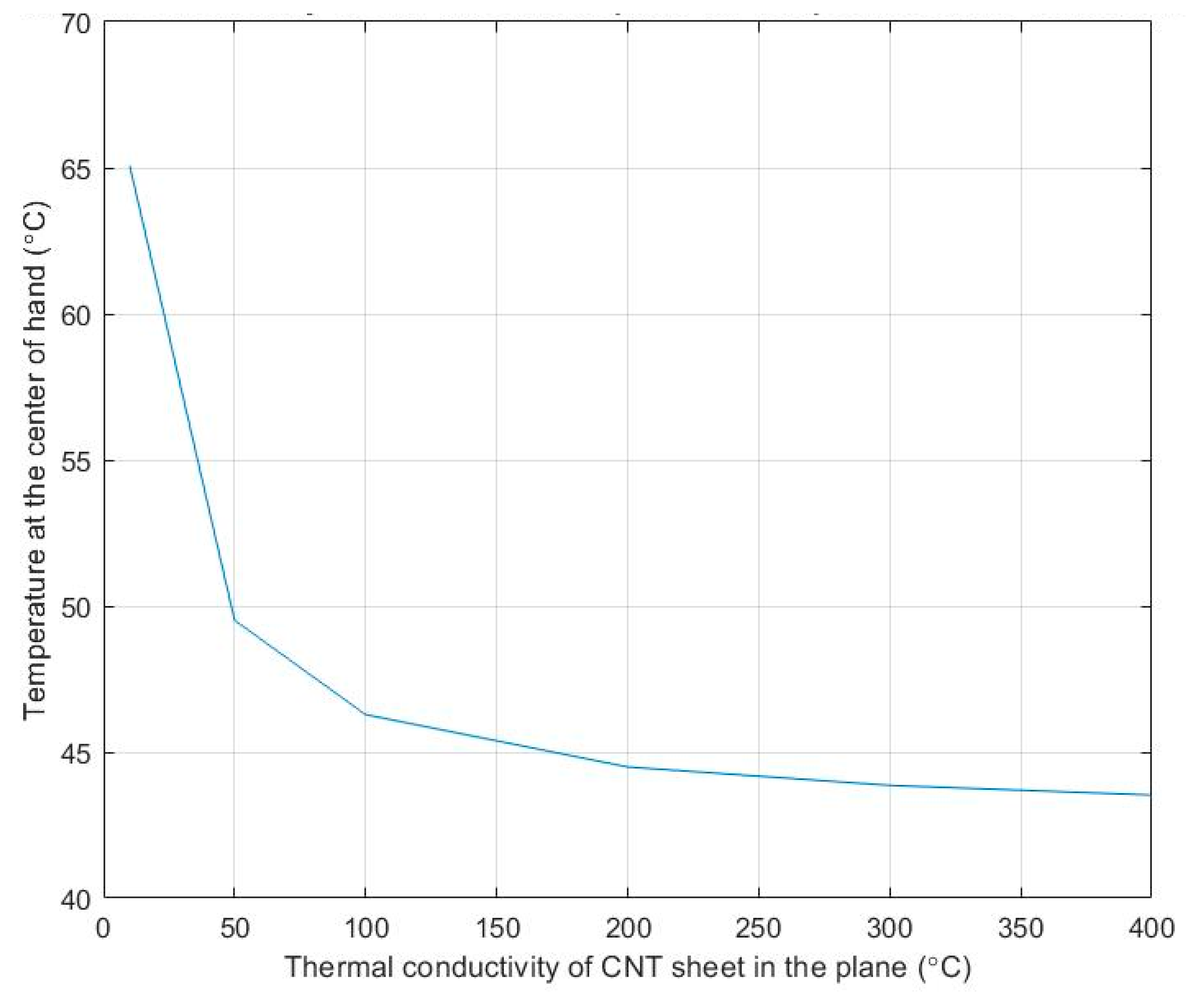
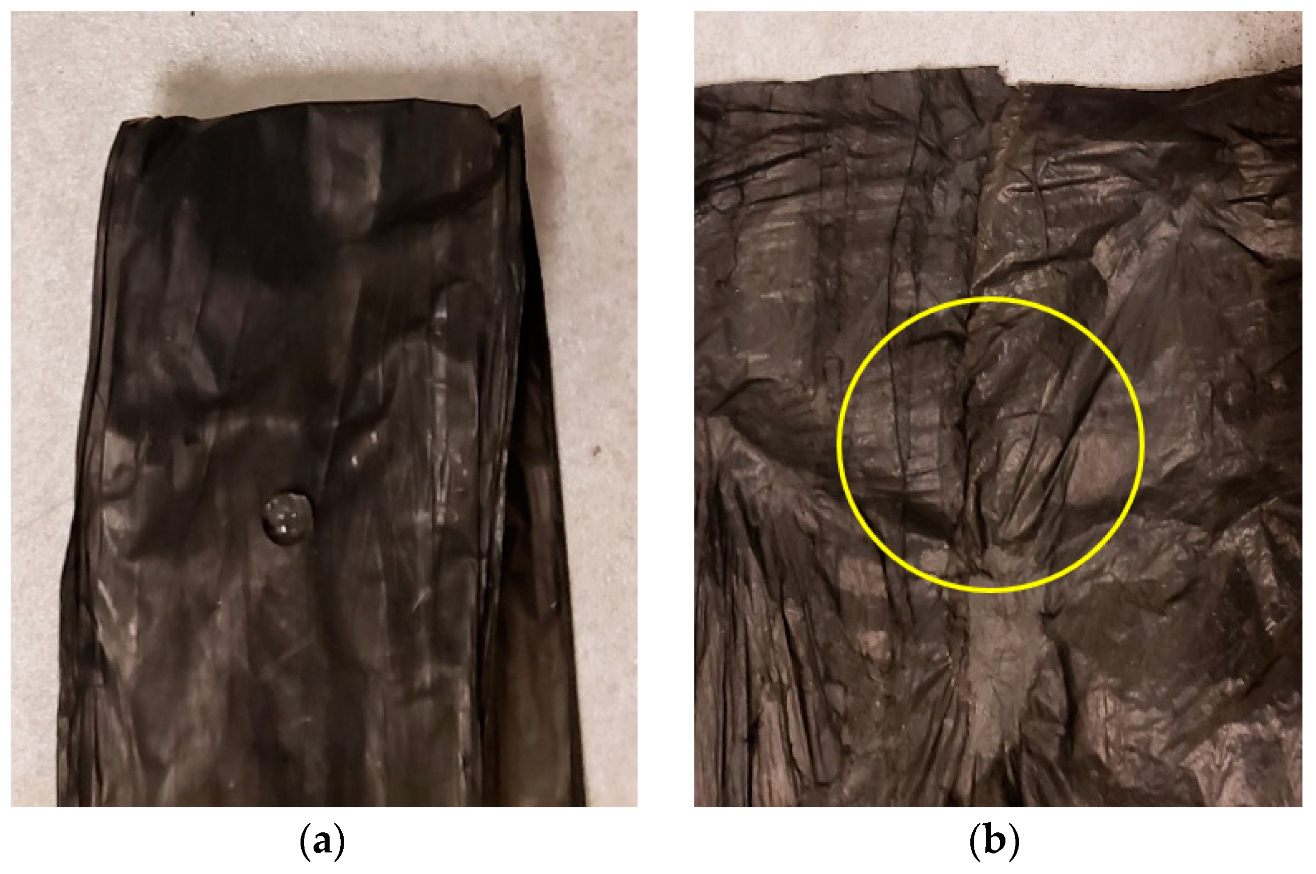
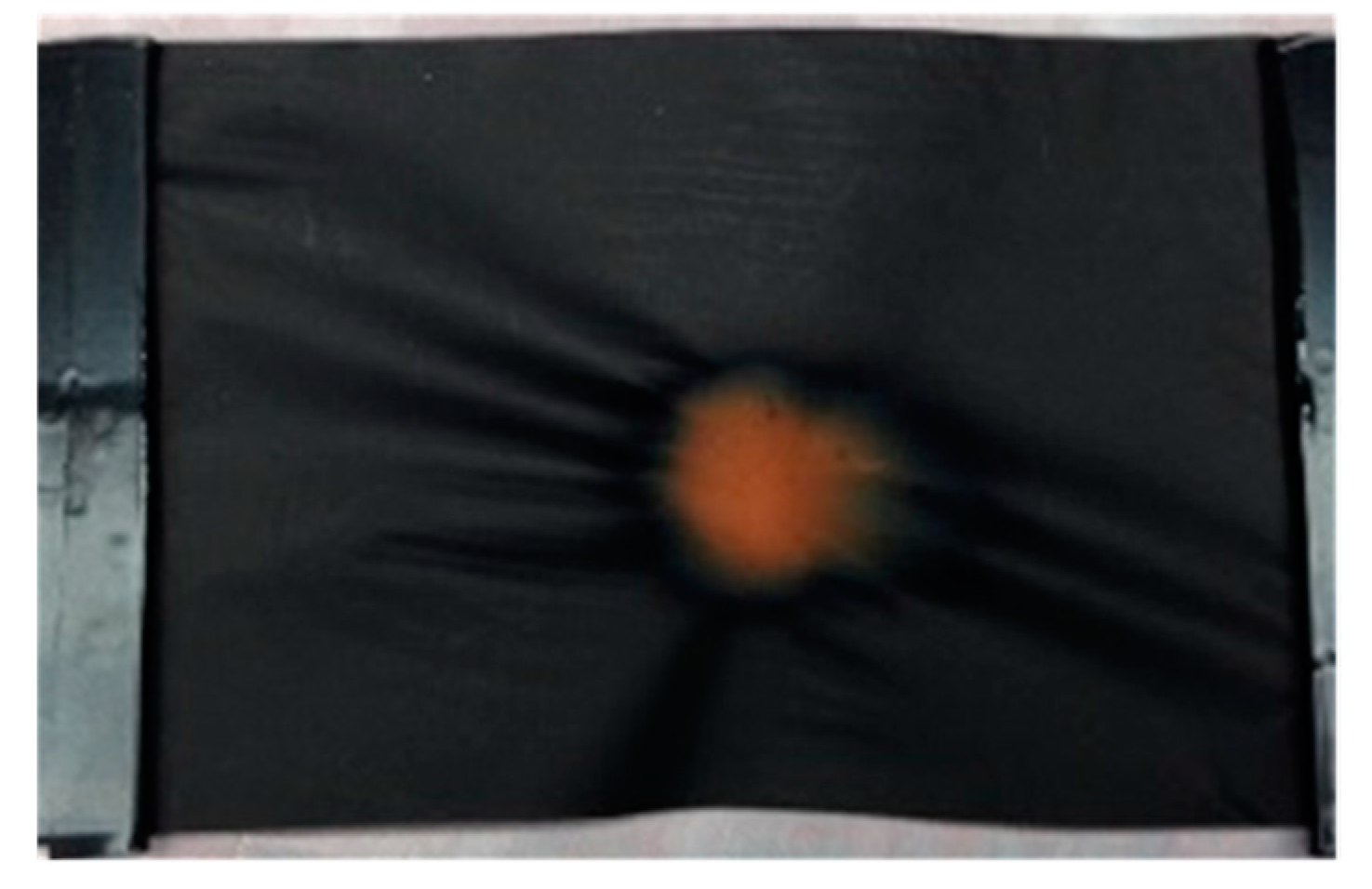
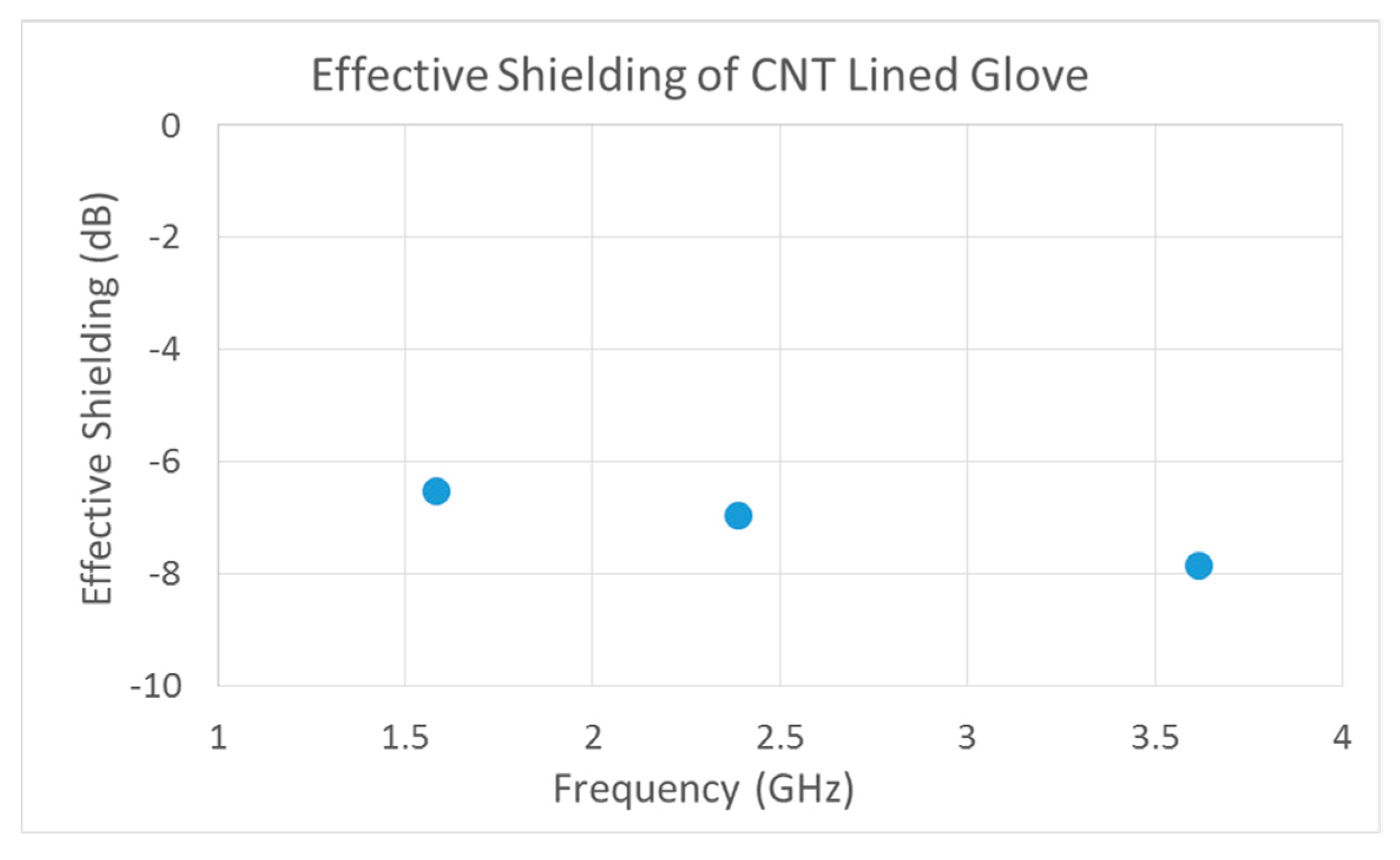
A problem with current types of gloves is that, on the one hand, they insulate or guard against heat input from a hot external environment. On the other hand, they prevent metabolic heat generated by the human body from escaping. Considering a hot external environment, and a high level of physical exertion, heat stress in workers can accumulate over time partially due to heat input to the body from the hands due to the insulating gloves. Heat stress can lead to hyperthermia (abnormally high body temperature) with symptoms of fatigue, sudden dizziness, cramps, exhaustion, and stroke. Firefighters—both structural and wildland-first responders—soldiers, industrial workers, and other front-line essential workers are at risk for hyperthermia. Therefore, apparel that can reduce heat stress can have safety and performance advantages. An active textile glove uses a carbon nanotube (CNT) fabric liner and forced convection to cool the hands. CNT fabric has high thermal conductivity in the plane of the fabric, but low thermal conductivity in the through the thickness direction of the fabric. Due to the high thermal conductivity in the plane of the fabric, and the heat transfer from the CNT fabric due to forced convection, a significant amount of heat can be transferred from the hand to the surrounding environment. Due to the low thermal conductivity through the thickness, CNT fabric can insulate the hands and forearms from heat generated by a high-temperature local environment. Thus, the directionality of the thermal conductivity of CNT fabric can be exploited in the design of safer gloves. The performance of a CNT cooled glove was simulated using simple theoretical heat transfer models programmed using MATLAB. The developed heat transfer algorithm incorporates conduction, convection, and an approximate model of radiation. The thermal performance of gloves with integrated CNT fabric and forced convection cooling was then predicted using this simulation model. Cooling using external air and using a cold sink was considered. Modeling enabled the optimal thickness and design of the glove fabric to be determined. The modeling showed that heat transfer in plane is limited by the small cross-sectional area of the thin CNT fabric, while heat transfer through the thickness of CNT fabric is significant due to the large surface area and the thin fabric. Heat transfer through the thickness also occurred by convection in the air space and radiation. Testing using a hot plate demonstrated the cooling of the glove. The greatest cooling was provided by forced convection. The CNT fabric aided in convection cooling. CNT fabric also has shielding properties, including flame resistance and the attenuating of radio frequency waves, and prevents environmental contaminants such as smoke particles and toxic chemicals from entering the glove. Testing demonstrated the shielding properties of the CNT fabric.
Usually, protective textiles are used when the wearer needs extra protection from external hazards [15]. When it comes to protective textiles, the wearer expects and assumes the textile will provide some form of thermal protection. In this paper, we report on CNT fabric having anisotropic or directional thermal conductivity properties. An example of the possible behavior of a fabric with directional thermal conductivity is given. Consider that a glove (textile containing CNT fabric) contacts a hot object. We expect, due to the directional thermal conductivity of the CNT layer, the heat will eventually spread across the area containing CNT fabric. As a result, this will possibly assist in regulating the wearer’s metabolic heat and the heat will not be localized to a single area (as in traditional flame retardant/resistant textiles). Thus, reporting the thermal performance of CNT fabric in active textiles is important because it may provide prolonged functional performance and protection against hot environment occupational hazards. Also, since the CNT fabric is thin, heat is transferred by conduction over short distances, but the heat is mainly transferred by convection owing to the surface area for convection being much larger than the cross-sectional area available for conduction.

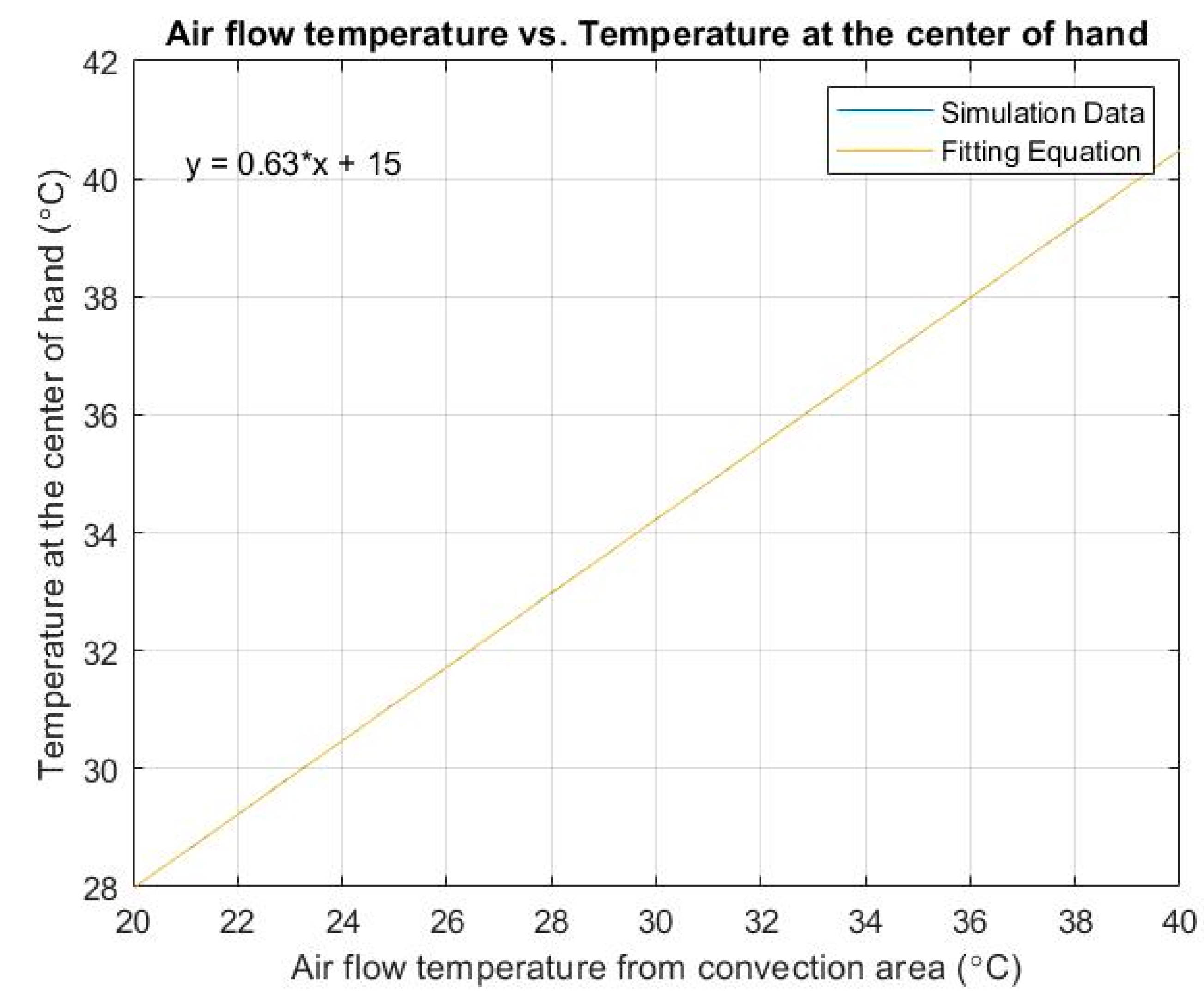
5. Summary and Conclusions

In the design of this cooled glove, the simulation model produced a similar trend in cooling to the prototype glove when air flow was allowed to circulate between the fabric layers in the glove. The temperature at the center of the hand decreased as the air flow velocity increased. The simulation results indicated that an air flow velocity of 1–2 m/s was appropriate for this model. The temperature of the convection area (i.e., the air used for cooling the glove) had a significant effect on the temperature at the center of the hand. As a result, the provision of a convection area at a low temperature is critical in the design of such gloves. Therefore, in hot conditions, a cold sink is needed in the design of gloves for FFs. Adding ice or a phase change material to the convection area in the cuff or the glove can provide the cool air needed for a limited time. The design of the FF glove was complicated and further optimization and study is needed. The purpose of the simulation model was to validate the feasibility of the application of CNT fabric in the FF glove. Therefore, a basic one-dimensional steady state model was useful for a preliminary understanding of the glove design. For the model to simulate the transient heat transfer, the simulation would have to be more complicated, and this will be considered for future work. If the glove design concept is successful in the future, it may increase safety for FFs, first responders, and other high-risk occupations by preventing a significant amount of heat generated by the high-temperature environment being transferred by reaching the hand. The glove can also spread metabolic heat. The added weight from the CNT fabric and cooling system is a trade-off in the design. Overall, the active textile glove with a micro CNT fabric layer and forced convection can reduce heat stress in FFs and first responders, which is a health benefit. The thin CNT fabric can protect against flame, potentially improve dexterity, and enable FFs to perform precise motions. The thermal insulation materials currently used are thick, impeding first responders’ work, thus decreasing operation accuracy. The shielding properties of CNT fabric are additional advantages and protect the FFs against toxic chemicals and smoke particles. A composited nanofabric with four layers was proposed for use in FF gloves. Looking ahead, the cost of CNT fabric must be reduced to make active textiles more practical.

Supplementary Materials

The following supporting information can be downloaded at: https://www.mdpi.com/article/10.3390/micro2010004/s1, Supplementary Description of The Analysis Equations

Author Contributions

Conceptualization, X.H., A.K., M.S.; methodology, all; software, X.H.; validation, X.H., T.N., D.M., V.N., M.S.; formal analysis, X.H., D.M.; investigation, all; writing, all. All authors have read and agreed to the published version of the manuscript.

Funding

This research was partially supported by the National Institute for Occupational Safety and Health Pilot Research Project Training Program of the University of Cincinnati Education and Research Center Grant No. #T42/OH008432. This research was also supported by UCTAC Seed Grant under ESP TECH Grant No. 15-0160.

Conflicts of Interest

The authors declare no conflict of interest. The funders had no role in the design of the study; in the collection, analyses, or interpretation of data; in the writing of the manuscript, or in the decision to publish the results.

References

  1. Das, A.; Alagirusamy, R.; Kumar, P. Study of heat transfer through multilayer clothing assemblies: A theoretical prediction. Department of Textile Technology, Indian Institute of Technology, New Delhi, India. AUTEX Res. J. 2011, 11, 54–60. [Google Scholar]
  2. Guan, M.; Annaheim, S.; Camenzind, M.; Li, J.; Mandal, S.; Psikuta, A.; Rossi, R.M. Moisture transfer of the clothing-human body system during continuous sweating under radiant heat. Text. Res. J. 2019, 89, 4537–4553. [Google Scholar] [CrossRef]
  3. Prasad, K.; Twilley, W.; Lawson, J.R. Thermal Performance of Firefighters’ Protective Clothing. Numerical Study of Transient Heat and Water Vapor Transfer; Fire Research Division, Building and Fire Research Laboratory; National Institute of Standards and Technology,; U.S. Department of Commerce: Gaithersburg, MD, USA, 2002.
  4. Sullivan, J.; Schulz, M.; Vemaganti, K.; Bhattacharya, A.; Jetter, B.J.; Shanov, V.; Alvarez, N.; Kim, J. Carbon Nanotube Fabric Cooling System for Firefighters and First Responders: Modeling and Simulation. J. Fiber Bioeng. Inform. 2015, 8, 1–12. [Google Scholar] [CrossRef]
  5. John, H.; Lienhard, I.V. A Heat Transfer Textbook, 5th ed.; Version 5.10 Dated 14 August 2020; Phlogiston Press: Cambridge, MA, USA, 2020. [Google Scholar]
  6. Kreith, F.; Manglik, R.M. Principles of Heat Transfer, 8th ed.; Library of Congress Control Number: 2016952399; Cengage Learning: Independence, KY, USA, 2017; ISBN 978-1-305-38710-2. [Google Scholar]
  7. Schulz, M.J.; Shanov, V.; Yin, Z.; Cahey, M. Nanotube Superfiber Materials: Science, Manufacturing, Commercialization; Elsevier: Amsterdam, The Netherlands, 2019; ISBN 978-0-12-812667-7. [Google Scholar]
  8. Jiang, S.; Liu, C.; Fan, S. Efficient natural-convective heat transfer properties of carbon nanotube sheets and their roles on the thermal dissipation. ACS Appl. Mater. Interfaces 2014, 6, 3075–3080. [Google Scholar] [CrossRef] [PubMed]
  9. Fahy, R.F.; Petrillo, J.T.; Verzoni, A. Report: On-Duty Firefighter Fatalities in 2020. NFPA Journal. 29 September 2021. Available online: https://www.nfpa.org/News-and-Research/Publications-and-media/NFPA-Journal/2021/Winter-2021/Reports/FF-Deaths-2020 (accessed on 1 September 2021).
  10. U.S. Fire Administration. Emmitsburg, MD 21727. Firefighter Fatalities Data. Available online: https://apps.usfa.fema.gov/firefighter-fatalities/fatalityData/list (accessed on 1 September 2021).
  11. Hou, X. Modeling Firefighter Apparel with Integrated Carbon Nanotube Fabric Layers for Cooling. Master’s Thesis, University of Cincinnati, College of Engineering and Applied Science, Cincinnati, OH, USA, July 2021. [Google Scholar]
  12. Sajjad, U.; Hamid, K.; Tauseef-ur-Rehman; Sultan, M.; Abbas, N.; Ali, H.M.; Imran, M.; Muneeshwaran, M.; Chang, J.; Wang, C.-C. Personal thermal management—A review on strategies, progress, and prospects. Int. Commun. Heat Mass Transf. 2022, 130, 105739. [Google Scholar] [CrossRef]
  13. Elgafy, A.; Mishra, S. A heat transfer model for incorporating carbon foam fabrics in firefighter’s garment. Heat Mass Transf. 2014, 50, 545–557. [Google Scholar] [CrossRef]
  14. Onofrei, E.; Petrusic, S.; Bedek, G.; Dupont, D.; Soulat, D.; Codau, T.C. Study of heat transfer through multilayer protective clothing at low-level thermal radiation. J. Ind. Text. 2015, 45, 222–238. [Google Scholar] [CrossRef]
  15. Paul, R. (Ed.) High Performance Technical Textiles; John Wiley & Sons: Hoboken, NJ, USA, 2019; ISBN 978-1-119-32503-1. [Google Scholar]
Figure 1. Theoretical heat transfer model of a glove system [11].
Micro 02 00004 g001
Figure 2. Temperature at the center of the hand versus air flow velocity. Note the temperature axis shows only the upper range temperature starting at 33 °C.
Micro 02 00004 g002
Figure 3. Temperature at the center of hand for different convection area air flow temperatures. The graph shows that a lower air flow temperature from the convection area reduces the temperature at the center of the hand. Simulation and fitting data overlay.
Micro 02 00004 g003
Figure 4. Temperature at the center of the hand versus in-plane thermal conductivity of CNT sheet. The CNT layer is conducting heat to a cold sink (not explicitly modeled) in the glove.
Micro 02 00004 g004
Figure 5. Schematic of modified commercial glove for cooling testing.
Micro 02 00004 g005
Figure 6. Interior of prototype glove constructed with fan, fabric flow tube, and CNT sheet strip located in the cuff of the glove. Arrows show air flow. No cold sink was used to cool the convection air in this prototype.
Micro 02 00004 g006
Figure 7. Testing equipment and glove prototype: (a) Cooling blower fan used in the designed prototype glove (WINSINN Blower Fan 12 V 50 mm 50 × 15 mm 5015 DC Brushless Cooling Dual Ball Bearing 0.28 A 3.36 W 6000 ± 5% RPM); (b) gain express four channel thermocouple data logger attached to two k-type thermocouples; (c) ANSA electronic hot plate to act as an external heat source; (d) prototype glove used in the thermal testing. The black hole area is the fan inlet. The silver area is a closed hole used to test the effect of the fan location. The glove was constructed by Mr. Travis Neuendorf.
Micro 02 00004 g007
Figure 8. Nanoglove fabricated with a CNT inner layer that covers the full area of the glove. (a) Glove being worn. (b) Glove on hot plate for qualitative thermal testing. Thermocouples are moved to different locations in the glove. This glove has three fabric layers.
Micro 02 00004 g008
Figure 9. Glove composited nanofabric with four layers. (a) edge view of fabric, from top, 1-inner comfort layer to go against the skin, 2-spacer knit air insulation layer, 3-CNT heat spreading and shielding layer, and 4-outer waterproof layer. (b) Glove fabric on hot plate with two blower fans and two thermocouples. The inside surface layer of the fabric is in contact with the thermocouples. The outside surface layer of the fabric is in contact with the hot plate.
Micro 02 00004 g009
Figure 10. Experimental setup for measuring the radio frequency shielding effectiveness of a CNT fabric lined glove. The thin CNT center fabric covers the full area of the glove.
Micro 02 00004 g010
Figure 11. Difference in the transmitted and received radio frequency signal with and without the CNT Lined Glove placed over GPS Patch antenna, plotted as a function of the frequency modes of the GPS Patch Antenna.
Micro 02 00004 g011
Figure 12. Water drop showing impermeability of CNT fabric. (a) CNT fabric with Ag-Cu nanoparticles inside is hydrophobic. (b) CNT fabric with granulated activated carbon (GAC) micro particles inside the fabric becomes hydrophilic (the water drop slowly seeped inside the fabric within the circle area).
Micro 02 00004 g012
Figure 13. Actuation testing of active textile fabric. (a) CNT fabric is impermeable to air and water and can be pressurized. The following are fabricated: a CNT composite or hybrid fabric with a woven outer layer to add strength; a CNT center layer that is impermeable; and a woven and plastic outer layer. (b) The composite fabric is held in a frame and pressurized using a small air pump and lifts a steel disk. The air filter, battery, and pump underneath the battery are shown in the figures.
Micro 02 00004 g013
Figure 14. Shielding testing of CNT fabric. CNT pristine fabric also resists flame. A flame is applied to thin CNT pristine fabric. The orange spot shows an iron oxide ceramic secondary phase refractory material that forms due to the flame. The CNT fabric spreads heat from the flame and the orange area resists burning.
Micro 02 00004 g014
Table 1. Temperature of the two sides of the hand with hot plate-with and without fan.
Hot Plate-50 °CTemperature at Center of Hand (°C)Temperature at Back of Hand (°C)
Without fan/air flow35.635.3
With fan/air flow34.235.1
Percentage Difference3.9%0.6%
Table 2. Temperature of air space on two sides of hand, no hot plate, with/without fan.
Condition of No Hot PlateWithout FanWith FanPercent Decrease
Temperature at center of hand (℃)33.330.48.8%
Table 3. Temperature of air space around the palm of the glove, glove on the hot plate, with/without fan, with/without hand inside glove. Hot plate is 70 °C, ambient air is 18 °C.
ConditionWithout FanWith FanPercent Decrease with Fan
Without hand in glove (no air flow restriction)37 °C22 °C40%
With hand in glove (air flow restriction)51 °C42 °C18%
Publisher’s Note: MDPI stays neutral with regard to jurisdictional claims in published maps and institutional affiliations.

