Article

Buckling Electrothermal NEMS Actuators: Analytic Design for Very Slender Beams

Department of Electrical and Electronic Engineering, Imperial College London, Exhibition Road, London SW7 2AZ, UK
*
Author to whom correspondence should be addressed.
Micro 2022, 2(1), 54-67; https://doi.org/10.3390/micro2010003
Submission received: 20 December 2021 / Revised: 5 January 2022 / Accepted: 10 January 2022 / Published: 13 January 2022
(This article belongs to the Section Microscale Engineering)

Abstract

:
Analytic approximations are presented for the response of buckling-mode electrothermal actuators with very slender beams with a width-to-length ratio of W / L 0.001 of the type found in nanoelectromechanical systems (NEMS). The results are found as closed-form solutions to the Euler beam bending theory rather than by an iterative numerical solution or a time-consuming finite element analysis. Expressions for transverse deflections and stiffness are presented for actuators with the common raised cosine and chevron pre-buckled shapes. The approximations are valid when the effects of bending dominate over those of axial compression. A few higher-order approximations are also presented for less slender beams with 0.001 W / L 0.01 .

1. Introduction

Electrothermal actuators are widely used in microelectromechanical systems (MEMS) because a device with in-plane motion may be constructed simply by etching and undercutting a mechanical layer to form a suspended structure that is heated by passing a current between the anchors [1]. The most common arrangements are shape bimorph [2,3] and buckling [4,5,6] actuators. Here, we focus on the latter, which have the general arrangement as shown in Figure 1a. Here, an array of beams is supported on anchors at either end. The beams are pre-buckled to force motion in the direction shown, tied together with a crossbeam at their midpoint to ensure collective motion, and driven by constrained thermal expansion.
If the beams are initially shaped into a chevron layout, the device is known as a V-beam actuator. The basis of actuation has been investigated using the Euler buckling theory and a finite element analysis [7,8], typically using the simplified single-beam model in Figure 1b. More recently, geometry effects [9], non-linearity [10], and dynamics [11,12] have been investigated, and there have been continuing attempts to improve the FEM analysis [13,14,15,16]. An alternative layout is the raised cosine pre-buckle in Figure 1c, which has been extensively analysed under the conditions leading to snap-through and bistability [17,18,19]. The thermal aspects of buckling actuators have also been modelled [20,21], and a new design—the Z-shaped actuator, which uses a stepped beam layout—has been developed [22,23,24]. More complex arrangements have been developed, including cascaded [7,25,26,27,28,29] and out-of-plane [30] actuators as well as actuators with a variable beam width [31,32], built-in strain gauges [33], and feedback control [34,35]. V-beam actuators have been used as the basis of linear [36,37,38] and rotary [36,39] stepping motors. Applications include electrical switches [40,41], optical alignment systems [42,43,44,45], tunable or scanning micro-optical devices [46,47,48], devices for cell manipulation [49,50,51], and movable neural microelectrode arrays [52,53]. The devices and applications are reviewed in [54].
Despite approximately twenty years of research, a few difficulties remain. Neither the analytic nor the finite element models of elastic deformation are very satisfactory. The former does not yield closed-form expressions and the latter requires excessive computation when the beams are very long and narrow and the number of elements is large. Apart from an analytic approximation for the deflection in [6], derived from purely geometric arguments, there are no closed-form design formulas so layouts are often chosen on an ad hoc basis. The aim of this paper is to remedy this deficiency by developing approximations to buckling theory that provide closed-form solutions. The solutions are valid for very slender beams with a width-to-length ratio in the approximate range of W / L 0.001 when bending dominates over axial compression; nanoelectromechanical systems (NEMS) actuators of this type capable of micron-scale deflections have been demonstrated by sidewall transfer lithography [55]. Raised cosine actuators and actuators with a chevron pre-buckle are analysed and discussed in Section 2. Additional results including alternative approximations, intrinsic stress, the relation between deflection and power, and transverse stiffness are considered in Section 3. Conclusions are drawn in Section 4.

2. Methods

We started by considering the raised cosine pre-buckle but followed the general approach used for V-beam actuators in [7]. We assumed a single beam with the shape shown in Figure 1c; the performance of the beam arrays could be estimated by scaling. The beam had a length L and central offset H , a rectangular cross-section with an in-plane width W and depth D , and was built-in at both ends. Its initial shape was:
y 0 ( x ) = H sin 2 ( π x L ) .
Forces F and moments M A modelled the effects of the anchors and the shape y ( x ) of the loaded beam could be found by solving the Euler buckling equation [56]:
E I d 2 ( y y 0 ) d x 2 = M ( x ) .
Here, M ( x ) = M A F y is the bending moment, I = W 3 D / 12 is the second moment of the area of the beam, and E is the Young’s modulus for the material used. An approximation implicit in the above was the replacement of the change in the beam curvature by the second derivative, which could clearly render the result inaccurate for a large pre-buckle or deflection. The analysis was best carried out by substituting y = y 0 + u , which yielded:
d 2 u d x 2 + ( F E I ) u = ( M A E I ) ( F E I ) y 0 .
Equation (3) may be solved in terms of a particular integral and a complementary function. Applying the boundary conditions u = d u d x = 0 at x = 0 and x = L , the result was:
u ( x ) = H { k 2 L 2 4 π 2 k 2 L 2 } sin 2 ( π x L ) .
Here, k = F / E I . This result demonstrated a special quality of the raised cosine pre-buckle: the deflected shape did not change. The midpoint deflection U = u ( L / 2 ) was:
U = H { k 2 L 2 4 π 2 k 2 L 2 } .
Equation (5) implies that U would be infinite when k L = 2 π , the Euler buckling condition. Integrating the deflected beam shape allowed the change in length L due to bending to be found as L = δ L δ L 0 , where we made the standard approximation δ L = 1 / 2 0 L ( d y d x ) 2 d x ; δ L 0 was the integral in the unloaded case (see, e.g., [9]). Integration gave:
L L = ( π 2 H 2 4 L 2 ) { k 2 L 2 ( 8 π 2 k 2 L 2 ) ( 4 π 2 k 2 L 2 ) 2 } .
The force F was derived from the constrained thermal expansion. Assuming an average temperature rise T a v g , the beam must satisfy a compatibility condition [7]:
F E W D = α T a v g L L .
Here, α is the linear thermal expansion coefficient of the beam material. The three terms in Equation (7) describe the changes in the length due to the axial compression, thermal expansion, and bending, respectively. This equation can also be written in the form:
α T a v g = L L + ( W L ) 2 ( k 2 L 2 12 ) .
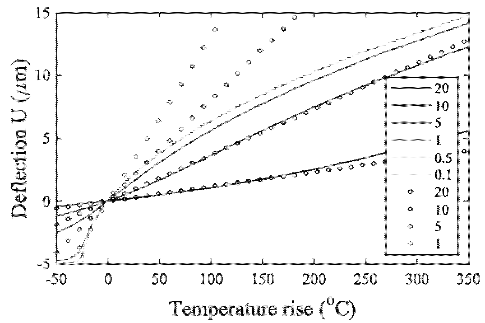
Equations (6) and (8) allowed T a v g to be found as a function of k L . As U is also a function of k L , it could be plotted as a function of T a v g . Alternatively, these coupled equations could be solved iteratively. For example, Figure 2 shows the variation of U with T a v g for a silicon beam with the following parameters: E = 170 × 10 9   Nm 2 , α = 2.6 × 10 6   K 1 , L = 1   mm , H = 5   μ m , D = 5   μ m , and values of W ranging from 20   μ m (MEMS domain) to 0.1   μ m (NEMS). In each case, the variation was similar. When the temperature rise T a v g was negative (so the beam was artificially cooled and under tension), U was negative and tended to H , straightening the beam. When T a v g was positive (so the beam was under compression), the deflection rose monotonically as the beam buckled. For values of W > 1   μ m , the variations differed; however, for W 1   μ m , the analytic solutions all tended to one another. Note, however, that for very large deflections, the approximation of the curvature changes by a second derivative in Equation (2) would no longer be valid.
Similar calculations were carried out using the commercial FEA solver, COMSOL® Multiphysics 4.4. A 2D model of a beam with a raised cosine pre-buckle and the dimensions above was built in the xy plane. The heat transfer module was used to apply a temperature change and the solid mechanics module to apply boundary constraints. Structural and thermal physics were coupled by thermal expansion in the multiphysics modelling interface. The plane stress approximation was used to eliminate the out-of-plane components of the stress tensor, and a stationary study was carried out using a geometrically non-linear analysis. The number of iterations was set to 50, with the solver automatically determining the damping factor for Newton’s method. In addition to the previous parameters, a Poisson’s ratio of ν = 0.28 was assumed. The discrete points in Figure 2 show the results for the four largest beam widths. The results were in good agreement with the analytic model for W = 20   μ m   and   W = 10   μ m but diverged for W = 5   μ m   and   W = 1   μ m ; for smaller values of W , convergence was not reached after 50 iterations.
A further difficulty was the increase in memory and run time as the W / L decreased. Table 1 shows the requirements for 37 temperature values using an Intel® CoreTM i7-2600 processor with a 3.4 GHz clock speed and 16 Gb RAM. The increase in the computation resource implied that the problem would rapidly become intractable, and these problems would worsen in 3D.
Although complete, the analytic solution above was still unsatisfactory because it required a numerical evaluation. A closed-form solution for U in terms of T a v g could allow the performance to be estimated directly from the geometric parameters. We obtained such a solution by first comparing Equations (5) and (6). It is simple to show that:
U 2 + 2 H U = ( 4 L 2 π 2 ) L L .
For slender beams with W / L 1 , we neglected the second term on the right-hand side of Equation (8), effectively neglecting the effects of axial compression. In this case, L / L = α T a v g , and Equation (9) approximated to the quadratic:
U 2 + 2 H U 4 α T a v g L 2 π 2 = 0 .
Equation (10) had two solutions. Retaining only the positive solution, the following expression for the deflection could be obtained:
U = H { 1 + 4 α T a v g L 2 π 2 H 2 1 } .
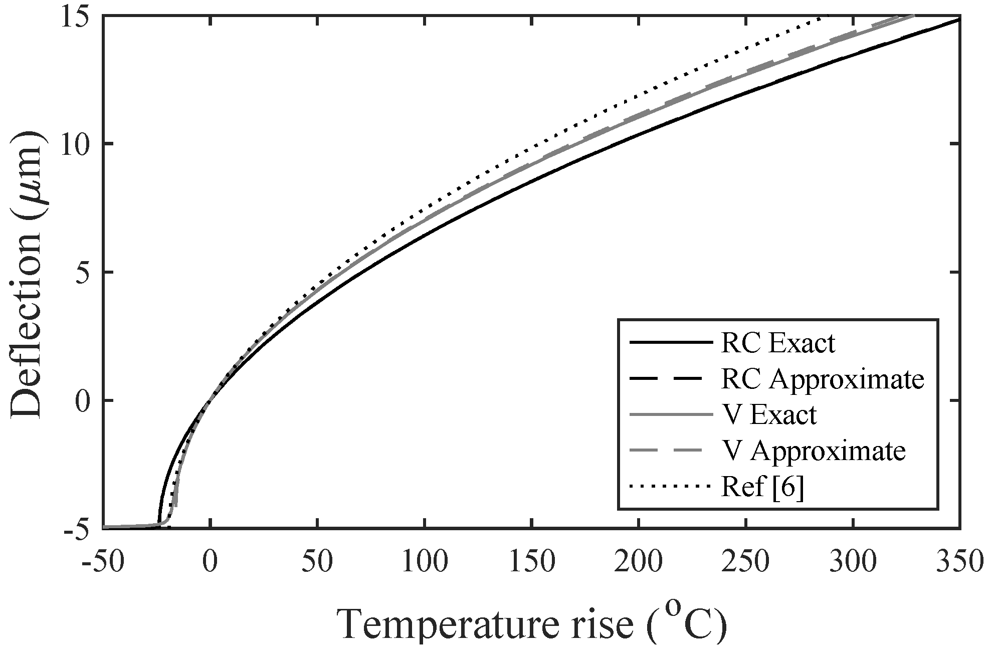
Equation (11) was the desired closed-form solution. It yielded a real result even when T a v g was negative until T a v g = π 2 H 2 / 4 α L 2 . Figure 3 compares the exact (axial stress included) and approximate (axial stress ignored) variation of the deflection with the average temperature rise for the same parameters as Figure 2 but with only the smallest beam width ( W = 0.1   μ m , for which W / L = 10 4 ). The agreement was excellent and the closed-form analytic formula tracked the exact solution closely, even when the deflection was large. Other curves are superimposed on this figure; these are discussed later.
We repeated the analysis for the V-beam actuator shown in Figure 1b. The beam had a length L and tilt angle θ so the central offset was H = ( L 2 ) tan ( θ ) . As y 0 is a linear function of x for 0 x L / 2 , Equation (2) could be written as d 2 y d x 2 + ( F E I ) y = M A E I in this range. The boundary conditions were y = 0 at x = 0 and d y d x = tan ( θ ) at x = 0 and x = L / 2 . The solution was [7]:
y ( x ) = tan ( θ ) k { sin ( k x ) + tan ( k L 4 ) { 1 cos ( k x ) } } .
This result implied that the beam changed shape significantly as it deflected, in contrast to the raised cosine actuator. The maximum deflection was U = ( y y 0 ) | L / 2 or:
U = 2 tan ( θ ) k { tan ( k L 4 ) k L 4 } .
Integrating the deflected beam shape again allowed the change in the length L due to bending to be found. The result was [7]:
L L = tan 2 ( θ ) 4 k L { 2 G [ 1 cos ( k L ) ] + ( 1 G 2 ) [ sin ( k L ) k L ] } .
Here, G = tan ( k L 4 ) . The compatibility equation was as before, and Equations (14) and (8) then allowed T a v g to be found as a function of k L . As Equation (13) was also a function of k L , U could again be plotted in terms of T a v g . The results are superimposed on Figure 3 for the same parameters as before. The deflections were very similar to the variations obtained for the raised cosine actuator, suggesting that the deflection in the V-beam actuator was dominated by the excitation of the lowest-order buckling-mode. The results obtained using COMSOL (not shown) again agreed well but suffered from an even worse scaling of run times with W / L .
The use of the very slender beam approach—relating U to L / L and then solving an approximate compatibility equation—could yield again an analytic approximation. This time, there were difficulties caused by the trigonometric functions in Equations (13) and (14). However, these could be circumvented using power series approximations. For example, substituting λ = k L / 4 allowed Equation (13) to be written as U L = tan ( θ ) f ( λ ) , where:
f ( λ ) = tan ( λ ) λ 2 λ .
As tan ( x ) = x + x 3 3 + 2 x 5 15 , we could approximate f to order λ 4 as:
f 4 ( λ ) = λ 2 6 + 2 λ 4 30 .
In a similar way, Equation (14) could be written as L L = tan 2 ( θ ) g ( λ ) , where:
g ( λ ) = 2   tan ( λ ) [ 1 cos ( 4 λ ) ] + [ 1 tan 2 ( λ ) ] [ sin ( 4 λ ) 4 λ ] 16 λ .
To simplify the above, we first noted that:
2   tan ( λ ) [ 1 cos ( 4 λ ) ] + [ 1 tan 2 ( λ ) ] sin ( 4 λ ) = 4   tan ( λ ) .
g ( λ ) could then be written as:
g ( λ ) = tan ( λ ) λ [ 1 tan 2 ( λ ) ] 4 λ .
With g in this form, we obtained a power series approximation to the order λ 4 as:
g 4 ( λ ) = λ 2 3 + 3 λ 4 15 .
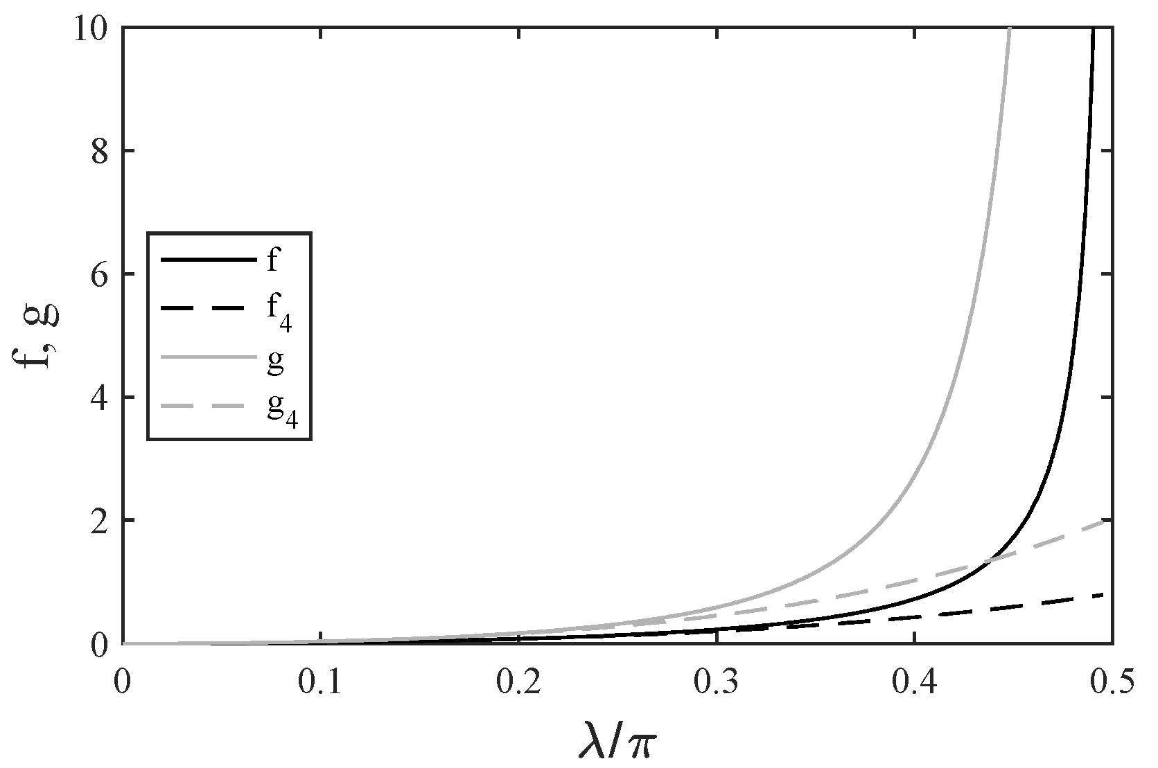
These simple approximations clearly had limited validity. Figure 4 compares the variations of f , f 4 , g , and g 4 with λ ; both approximations were accurate only up to λ 0.3   π , well below the buckling condition (when f and g both became infinite).
Despite this, they allowed useful closed-form solutions. For example, combining Equations (16) and (20), we obtained:
g 4 2 f 4 + 12 f 4 2 5 .
Rearranging, we obtained the quadratic equation:
12 f 4 2 5 + 2 f 4 g 4 = 0 .
Retaining only the positive root, we obtained:
f 4 = 5 12 { 1 + 12 g 4 5 1 } .
Noting the original definitions of f and g , we then obtained the midpoint deflection U as:
U = 5 L   tan ( θ ) 12 { 1 + 12 L 5 L   tan 2 ( θ ) 1 } .
Neglecting the second term in the RHS of Equation (8) as before, we then obtained:
U = 5 L   tan ( θ ) 12 { 1 + 12 α T a v g 5   tan 2 ( θ ) 1 } .
This result can, of course, be written in the alternative form:
U = 5 H 6 { 1 + 3 α T a v g L 2 5 H 2 1 } .
Equation (26) was analogous to Equation (11) for the raised cosine pre-buckle. The predictions of this closed-form solution are superimposed on Figure 3 for the same parameters. Once again, there was a good agreement with the full model despite the apparent errors in f 4 and g 4 . We constructed higher-order expansions of both functions and found that the expressions above gave good results despite their simplicity.
The performances of the two designs were clearly similar; however, the V-beam actuator gave a slightly larger deflection for a given temperature rise. Equations (11) and (26) could both be written in the form U = A { 1 + B T a v g 1 } . Consequently, the initial sensitivity S = d U / d T a v g | 0 of the deflection to temperature was S = A B / 2 . For the two actuator types, the sensitivities S R C and S V were:
S R C = 2 α L 2 π 2 H                                                                                                                         S V = α L 2 4 H         .
Thus, the sensitivity was always proportional to L 2 and inversely proportional to H . For a common geometry, S V / S R C = π 2 / 8 , so the V-beam design was slightly more sensitive.

3. Results

In this section, we discuss several alternative results, power scaling laws and the related question of transverse stiffness. We started by considering the well-known formula for the deflection of a V-beam actuator derived in [6] by considering that the two beam sections remained straight and simply increased in length by an amount L h due to thermal expansion. Using a first-order approximation we obtained:
U = L h 2 + 2 L h L h L h 2 cos ( θ ) L h sin ( θ ) .
Here, L h = L / 2 . Rearranging and substituting H for L h sin ( θ ) and α T a v g for L h / L h we obtained:
U = H { 1 + α T a v g L 2 2 H 2 1 } .
Equation (28) may also be written in the form U = A { 1 + B T a v g 1 } . Its predictions are also shown superimposed on Figure 3. It was clearly less accurate than Equation (26); however, the prediction was remarkable given that bending was entirely ignored.
We then considered alternative approximations for a raised cosine actuator that could be viable for less slender beams when the axial compression term in Equation (8) could not be neglected. Retaining this term, it was simple to show that Equation (10) becomes:
U 2 + 2 H U ( 4 L 2 π 2 ) α T a v g = 4 W 3 U 3 U ( H + U ) .
Thus, a more exact relation between U and T a v g was a cubic equation. Clearly, Equation (30) had a numerical solution. However, in the spirit of the present MS, where the focus is on solutions that yielded an insight, we derived an analytic approximation. We assumed that U = U 0 + U 1 , where U 0 was the solution to Equation (10) and U 1 was an additional perturbation. Substituting and neglecting the higher-order terms, it was simple to obtain:
U 1 = 2 W 2 U 0 3 ( H + U 0 ) 2 .
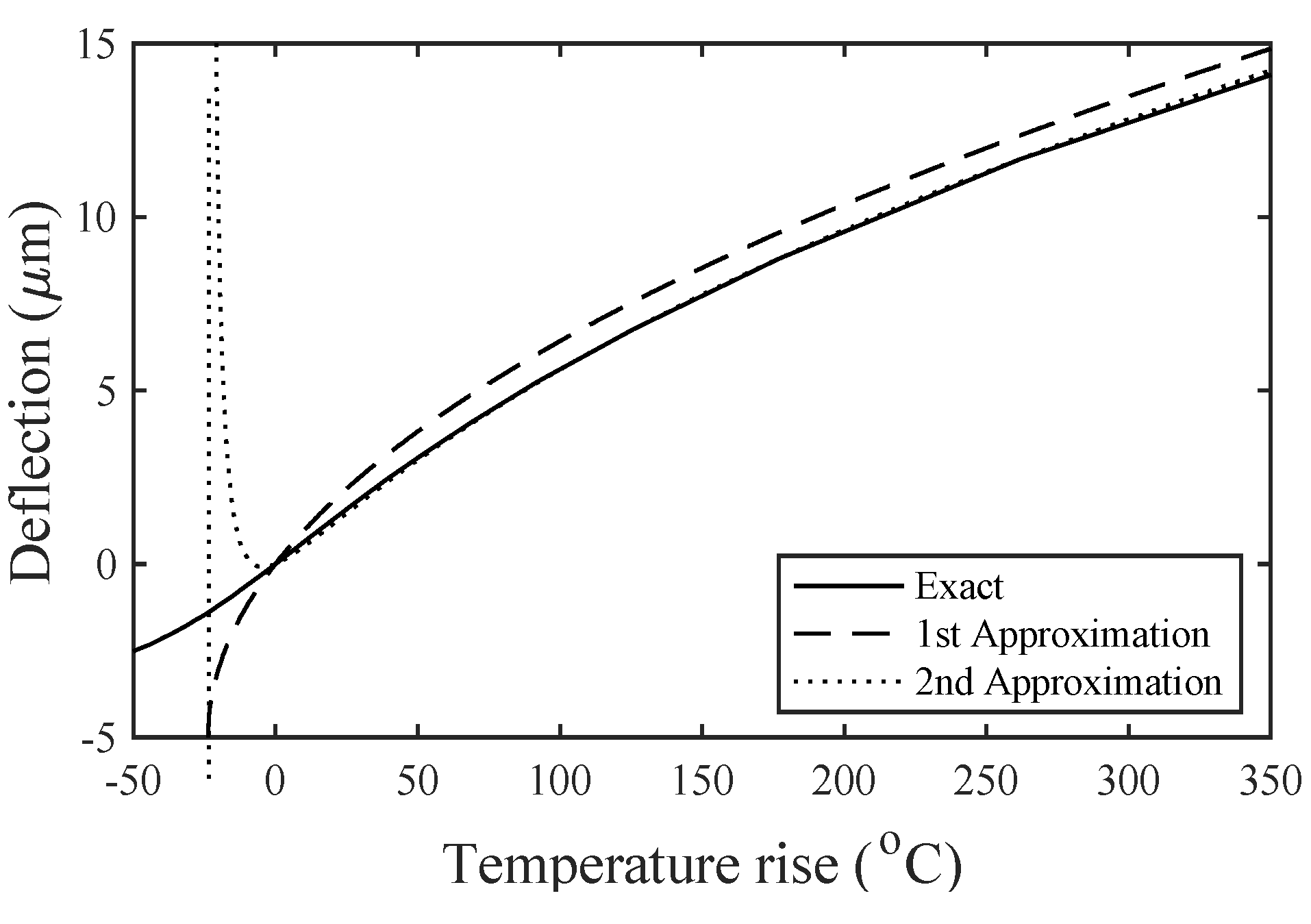
Thus, the effect of axial compression was to reduce the deflection by an amount that depended on W and (for small deflections) was linearly proportional to U 0 . Consequently, the initial slope of the deflection characteristic must reduce for wider beams. To illustrate this, Figure 5 compares the exact solution, the first approximation (11), and the second approximation (31). The parameters were as before, but the beam width W was increased to 5   μ m (so that W / L = 5 × 10 3 ). This width was sufficiently large that the first approximation was no longer valid. However, the second approximation was a good match to the exact solution except when U 0 tended to H . This behaviour was to be expected from Equation (31); it is unimportant for practical applications when positive temperature rises are the norm.
We noted that the addition of a tensile stress σ (which could arise during processing) inserted an axial strain term σ / E into Equation (8). The intrinsic stress could, therefore, be included by replacing T a v g with T a v g σ / E in the preceding expressions. The effect of stress was, therefore, to shift the deflection characteristics to the right. If measurements were made from the rest, the effect was to reduce the apparent deflection.
Finally, we considered the well-known relation between temperature and power (see, e.g., [9,10]). If the beam was heated by a power P and cooled only by thermal conduction to the anchors, the steady-state temperature rise T ( x ) was the solution to the heat conduction equation:
k t h W D d 2 T d x 2 + P L = 0 .
Here, k t h was the thermal conductivity of the beam material. The solution subject to the boundary conditions T = 0 at x = 0 and x = L was:
T ( x ) = T m a x 4 ( x L x 2 ) L 2 .
Here, T m a x was the temperature at x = L / 2 . The average temperature could then be found by the integration of the temperature profile along the beam length as:
T a v g = P L 12 k t h W D .
The previous expressions for deflection could be converted into variations with power by making this substitution; for an N -beam array, P was simply divided by N . Similarly, for a device that was also cooled by gas conduction to the substrate, P was multiplied by an efficiency term, η .
We then considered the transverse stiffness of a buckling actuator and showed how the slender beam approximation could be used to evaluate this quantity for the raised cosine type. Following previous authors [7], we assumed that the stiffness was found from the transverse force F T needed to return the midpoint deflection to zero. Unfortunately, the application of F T altered the axial force to a new value, F , and altered the end moment to M A . At a certain point, the rising transverse force will lead to snap-through [9], so the analysis was carried out with caution. To find the deflection u ( x ) , we solved:
d 2 u d x 2 + ( F E I ) u = M A E I ( F E I ) y 0 + ( F T 2 E I ) x                                                   0 x L 2
d 2 u d x 2 + ( F E I ) u = M A E I ( F E I ) y 0 ( F T 2 E I ) ( L x )                     L / 2 x L .
The variation of u was symmetric about the midpoint. For 0 x L / 2 , it could be found by standard methods as:
u ( x ) = C 1 { k x sin ( k x ) + tan ( k L 4 ) [ cos ( k x ) 1 ] } + C 0 sin 2 ( π x L ) .
Here:
C 0 = H { k 2 L 2 4 π 2 k 2 L 2 }                                                           C 1 = F T 2 k 3 E I                                                   k = F / E I .
The midpoint deflection U = u ( L / 2 ) was then:
U = C 1 { k L 2 2   tan ( k L 4 ) } + C 0 .
Now, to return U to zero, we required a transverse force such that:
C 1 = C 0 2   tan ( k L 4 ) k L 2 .
As k was unknown, a further condition was required to determine F T . This could be obtained from the compatibility. As the temperature was unchanged by the transverse force, we had L / L = L / L , where L / L = 1 / L 0 L / 2 ( d y d x ) 2 d x . To proceed, we started with the deflected shape:
d y d x = C 1 k { 1 cos ( k x ) tan ( k L 4 ) sin ( k x ) } + ( C 2 π L ) sin ( 2 π x L ) .
Here, C 2 = H { 4 π 2 4 π 2 k 2 L 2 } . Consequently:
d y d x = C 1 k { 1 cos ( k x ) tan ( k L 4 ) sin ( k x ) } + ( C 2 π L ) sin ( 2 π x L ) .
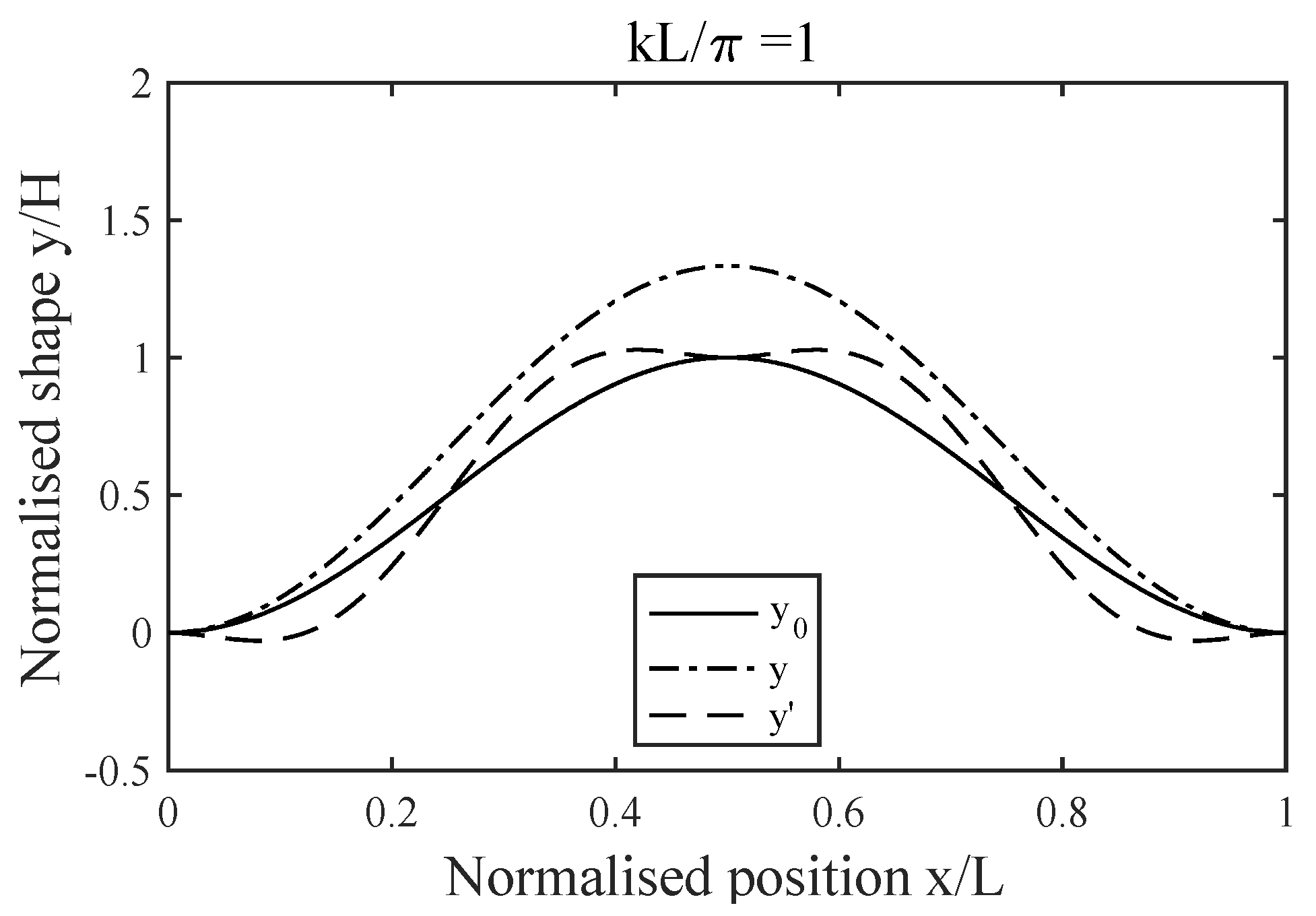
Using the above, the integral determining L / L could be evaluated, numerically or analytically. However, the expressions obtained in the latter case were non-linear in k . In each case, the values of F T and F were, therefore, generally found by iteration to satisfy the conditions above for a given F . Figure 6 shows a typical result, where the initial shape y 0 ( x ) , the actuated shape y ( x ) , and the centrally loaded shape y ( x ) were plotted together for k L = π . The overall deflection increased as the actuator was driven, retaining a raised cosine shape; the midpoint deflection correctly returned to zero as the actuator was loaded.
A simple analytic solution for the transverse stiffness could be obtained by assuming that k L was small and by making power series approximations to Equation (40). This process yielded:
d y d x C 1 k 3 { x 2 2 L x 4 } + ( C 2 π L ) sin ( 2 π x L ) .
Squaring and integrating, we then obtained:
L / L C 1 C 2 k 3 L 2 π 2 + C 2 2 π 2 4 L 2 .
At a similar level of approximation, we had:
C 0 = H k 2 L 2 4 π 2                                                                                                                             C 1 = 24 H π 2 k L
C 2 = H { 1 + k 2 L 2 4 π 2 }                                                                                                     L L = { 1 + k 2 L 2 2 π 2 } ( π 2 H 2 4 L 2 ) .
A substitution into the compatibility condition then yielded an approximation for k as:
k 2 k 2 = 1 1 96 π 4 69 .
Thus, the action of forcing the actuator back to its starting point increased k significantly from the original value k due to electrothermal actuation alone. To find the transverse stiffness, we noted that F T and U could be approximated as:
F T 48 k 2 E I H π 2 L                                                                                                                                       U H k 2 L 2 4 π 2 .
Consequently, the transverse stiffness k T = F T / U could be extracted as:
k T = ( k 2 k 2 ) ( 192 E I L 3 ) .
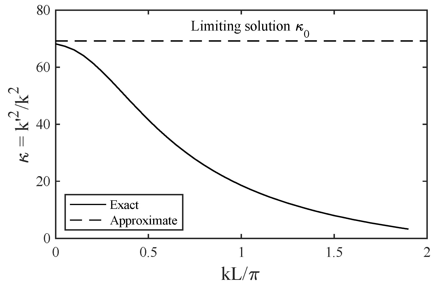
The term k T 0 = 192 E I / L 3 was then the transverse stiffness of a straight, centrally loaded built-in beam. Shaping the beam and adding restraints at either end raised the stiffness by a factor of 69, as shown above. More generally, the transverse stiffness could always be written in the form k T = κ k T 0 , where κ was a coefficient that depended on the initial value of k . Figure 7 shows the numerically calculated variation of κ with k L . This fell monotonically from an initial value of 69, implying that the actuator became weaker and weaker as it deflected.

4. Conclusions

We presented analytic approximations to the results of the Euler theory that allowed the response of buckling-mode electrothermal actuators to be obtained in a closed-form, avoiding the need for an iterative solution of coupled analytic equations or a lengthy finite element analysis. The approximations were valid for actuators with very slender beams (such as NEMS designs) when the effects of bending dominated over those of axial compression. We compared the expressions with numerical solutions and showed them to be extremely accurate. We also presented higher-order corrections for less slender beams as found in MEMS actuators.
The analysis focused on two specific actuator layouts based on V-beam and raised cosine beam shapes. Each had the same set of material parameters ( E ,   α ,   and   k t h ) and geometric design parameters ( W ,   L ,   D ,   and   H ). The careful choice of the latter allowed well-known trade-offs between drive power, frequency response, and mechanical stiffness but the closed form Equations (11) and (26) and the results in Figure 3 showed that there was little to choose between the two layouts for a fixed set of parameters. However, the approximation used (neglect of axial stress) may open the door to analytic design optimisation in more general cases; for example, when the beam width or other properties vary locally.

Author Contributions

Conceptualization, R.S. and D.L.; methodology, R.S.; formal analysis, R.S.; investigation, R.S. and D.L.; writing—original draft preparation, R.S.; writing—review and editing, D.L.; supervision, R.S.; All authors have read and agreed to the published version of the manuscript.

Funding

This research received no external funding.

Conflicts of Interest

The authors declare no conflict of interest.

References

  1. Noworolski, J.M.; Klaassen, E.H.; Logan, J.R.; Petersen, K.E.; Maluf, N.I. Process for in-plane and out-of-plane single-crystal-silicon thermal microactuators. Sens. Actuators A 1996, 55, 65–69. [Google Scholar] [CrossRef]
  2. Pan, C.S.; Hsu, W. An electro-thermally and laterally driven polysilicon microactuator. J. Micromech. Microeng. 1997, 7, 7–13. [Google Scholar] [CrossRef]
  3. Comtois, J.H.; Michalecik, M.A.; Barron, C.C. Electrothermal actuators fabricated in four-level planarized surface micromachined polycrystalline silicon. Sens. Actuators A 1998, 70, 23–31. [Google Scholar] [CrossRef]
  4. Cragun, R.; Howell, L.L. Linear thermomechanical actuators. In ASME International Mechanical Engineering Congress and Exposition; American Society of Mechanical Engineers: New York, NY, USA, 1999; Volume 16387, pp. 181–188. [Google Scholar] [CrossRef]
  5. Que, L.; Park, J.; Gianchandani, Y. Bent-beam electrothermal actuators for high force applications. In Proceedings of the Technical Digest. In Proceedings of the IEEE International MEMS 99 Conference. Twelfth IEEE International Conference on Micro Electro Mechanical Systems, Orlando, FL, USA, 21 January 1999; pp. 31–36. [Google Scholar] [CrossRef]
  6. Sinclair, M.J. A high force low area MEMS thermal actuator. In Proceedings of the ITHERM 2000. The Seventh Intersociety Conference on Thermal and Thermomechanical Phenomena in Electronic Systems, Las Vegas, NV, USA, 23–26 May 2000; pp. 127–132. [Google Scholar] [CrossRef]
  7. Que, L.; Park, J.-S.; Gianchandani, Y.B. Bent-beam electrothermal actuators—Part I: Single-beam and cascaded devices. J. Microelectromech. Syst. 2001, 10, 247–254. [Google Scholar] [CrossRef] [Green Version]
  8. Enikov, E.T.; Kedar, S.S.; Lazarov, K.V. Analytical model for analysis and design of V-shaped thermal microactuators. J. Microelectromech. Syst. 2005, 14, 788–798. [Google Scholar] [CrossRef]
  9. Hoang, K.T.; Nguyen, D.T.; Pham, P.H. Impact of design parameters on working stability of the electrothermal V-shaped actuator. Microsyst. Technol. 2020, 26, 1479–1487. [Google Scholar] [CrossRef]
  10. Hussein, H.; Fariborzi, H.; Younis, M.I. Modeling of beam electrothermal actuators. J. Microelectromech. Syst. 2020, 29, 1570–1581. [Google Scholar] [CrossRef]
  11. Chen, H.; Wang, X.-J.; Wang, J.; Xi, Z.-W. Analysis of the dynamic behaviour of a V-shaped electrothermal microactuator. J. Micromech. Microeng. 2020, 30, 085005. [Google Scholar] [CrossRef]
  12. Alcheikh, N.; Ouakad, H.M.; Younis, M.I. Dynamics of V-shaped electrothermal MEMS-based resonators. J. Microelectromech. Syst. 2020, 29, 1372–1381. [Google Scholar] [CrossRef]
  13. Baracu, A.; Voicu, R.; Müller, R.; Avram, A.; Pustan, M.; Chiorean, R.; Birleanu, C.; Dodescu, C. Design and fabrication of a MEMS Chevron-type thermal actuator. AIP Conf. Proc. 2015, 25, 25–30. [Google Scholar] [CrossRef] [Green Version]
  14. Shan, T.; Qi, X.; Cui, L.; Zhou, X. Thermal behaviour modelling and characteristics analysis of electrothermal microactuators. Microsyst. Technol. 2017, 23, 2629–2640. [Google Scholar] [CrossRef]
  15. Thangavel, A.; Rengaswamy, R.; Sukumar, P.K.; Sekar, R. Modelling chevron electrothermal actuator and its performance analysis. Microsyst. Technol. 2018, 24, 1767–1774. [Google Scholar] [CrossRef]
  16. Sciberras, T.; Demicoli, M.; Grech, I.; Mallia, B.; Mollicone, P.; Sammut, N. Coupled finite element-finite volume multi-physics analysis of MEMS electrothermal actuators. Micromachines 2022, 13, 8. [Google Scholar] [CrossRef]
  17. Vangbo, M. An analytical analysis of a compressed bistable buckled beam. Sens. Actuators A 1998, 69, 212–216. [Google Scholar] [CrossRef]
  18. Qiu, J.; Lang, H.; Slocum, A.H. A curved-beam bistable mechanism. J. Microelectromech. Syst. 2004, 13, 137–146. [Google Scholar] [CrossRef]
  19. Park, S.; Hah, D. Pre-shaped buckled beam actuators: Theory and experiments. Sens. Actuators A 2008, 148, 186–192. [Google Scholar] [CrossRef]
  20. Lott, C.D.; McLain, T.W.; Harb, J.N.; Howell, L.L. Modeling the thermal behaviour of a surface micromachined linear-displacement thermomechanical microactuator. Sens. Actuators A 2002, 101, 239–250. [Google Scholar] [CrossRef] [Green Version]
  21. Hickey, R.; Sameoto, D.; Hubbard, T.; Kujath, M. Time and frequency response of two-arm micromachined thermal actuators. J. Micromech. Microeng. 2003, 13, 40. [Google Scholar] [CrossRef]
  22. Zhu, Y.; Reza Moheimani, S.O.; Yuce, M.R. Bidirectional electrothermal actuator with Z-shaped beams. IEEE Sens. J. 2012, 12, 2508–2509. [Google Scholar] [CrossRef] [Green Version]
  23. Zhang, Z.; Zhang, W.; Wu, Q.; Yu, Y.; Liu, X.; Zhang, X. Closed-form modelling and design analysis of V- and Z-shaped electrothermal microactuators. J. Micromech. Microeng. 2017, 27, 015023. [Google Scholar] [CrossRef]
  24. Zhang, Z.; Yu, Y.; Liu, X.; Zhang, X. Dynamic modelling and analysis of V- and Z-shaped electrothermal microactuators. Microsyst. Technol. 2017, 23, 3775–3789. [Google Scholar] [CrossRef]
  25. Chu, L.L.; Hetrick, J.A.; Gianchandani, Y.B. High amplification compliant micro-transmissions for rectilinear electrothermal actuators. Sens. Actuators A 2002, 97–98, 776–783. [Google Scholar] [CrossRef]
  26. Zhang, Y.; Huang, Q.-A.; Li, R.-G.; Li, W. Macro-modeling for polysilicon cascaded bent beam electrothermal microactuators. Sens. Actuators A 2006, 128, 165–175. [Google Scholar] [CrossRef]
  27. Hubbard, N.B.; Howell, L.L. Design and characterization of a dual-stage, thermally actuated nanopositioner. J. Micromech. Microeng. 2005, 15, 1482–1493. [Google Scholar] [CrossRef]
  28. Shen, X.; Chen, X. Mechanical performance of a cascaded V-shaped electrothermal actuator. J. Adv. Robot. Syst. 2013, 10, 379. [Google Scholar] [CrossRef]
  29. Alcheikh, N.; Hajjaj, A.Z.; Jaber, N.; Younis, M.I. Electrothermally actuated tunable clamped-guided resonant microbeams. Mech. Syst. Signal Process. 2018, 98, 1069–1076. [Google Scholar] [CrossRef]
  30. Varona, J.; Tecpoyotl-Torres, M. Design of MEMS vertical-horizontal chevron thermal actuators. Sens. Actuators A 2009, 153, 127–130. [Google Scholar] [CrossRef]
  31. Sassen, W.P.; Henneken, V.A.; Tichem, M.; Sarro, P.M. Contoured V-beam actuator with improved temperature uniformity. Sens. Actuators A 2008, 144, 341–347. [Google Scholar] [CrossRef]
  32. Kwan, A.M.H.; Song, S.; Lu, X.; Lu, L.; Teh, Y.K.; Teh, Y.F.; Chong, E.W.C.; Gao, Y.; Hau, W.; Zeng, F.; et al. Improved designs for an electrothermal in-plane microactuator. J. Microelectromech. Syst. 2012, 21, 587–595. [Google Scholar] [CrossRef]
  33. Wittwer, J.W.; Baker, M.S.; Howell, L.L. Simulation, measurement, and asymmetric buckling of thermal microactuators. Sens. Actuators A 2006, 128, 395–401. [Google Scholar] [CrossRef]
  34. Chu, L.L.; Gianchandani, Y.B. A micromachined 2D positioner with electrothermal actuation and sub-nanometer capacitive sensing. J. Micromech. Microeng. 2003, 13, 279–285. [Google Scholar] [CrossRef] [Green Version]
  35. Messenger, R.K.; Aten, Q.T.; McLain, T.W.; Howell, L.L. Piezoresistive feedback control of a MEMS thermal actuator. J. Microelectromech. Syst. 2009, 18, 1267–1278. [Google Scholar] [CrossRef] [Green Version]
  36. Park, J.; Chu, L.L.; Oliver, A.D.; Gianchandani, Y.B. Bent-beam electrothermal actuators—Part II: Linear and rotary microengines. J. Microelectromech. Syst. 2001, 10, 255–262. [Google Scholar] [CrossRef]
  37. Maloney, J.M.; Schreiber, D.S.; DeVoe, D.L. Large force electrothermal linear micromotors. J. Micromech. Microeng. 2004, 14, 226–234. [Google Scholar] [CrossRef] [Green Version]
  38. Brown, M.; Hubbard, T.; Kujath, M. Development of a long-range untethered frictional microcrawler. J. Micromech. Microeng. 2007, 17, 1025–1033. [Google Scholar] [CrossRef]
  39. Geisberger, A.; Kadylak, D.; Ellis, M. A silicon electrothermal rotational micro motor measuring one cubic millimeter. J. Micromech. Microeng. 2006, 16, 1943–1950. [Google Scholar] [CrossRef]
  40. Wang, Y.; Li, Z.; McCormick, D.T.; Tien, N.C. A micromachined RF microrelay with electrothermal actuation. Sens. Actuators A 2003, 103, 231–236. [Google Scholar] [CrossRef]
  41. Wang, Y.; McCormick, D.T.; Tien, N.C. A low-voltage lateral MEMS switch with high RF performance. J. Microelectromech. Syst. 2004, 13, 902–911. [Google Scholar] [CrossRef]
  42. Syms, R.R.A.; Zou, H.; Stagg, J. Robust latching MEMS translation stages for micro-optical systems. J. Micromech. Microeng. 2004, 14, 667–674. [Google Scholar] [CrossRef] [Green Version]
  43. Unamuno, A.; Yao, J.; Uttamchandani, D. Alignment and fixing of fiber optics based on electrothermal MEMS actuators. IEEE Photon. Tech. Lett. 2005, 17, 816–818. [Google Scholar] [CrossRef]
  44. Syms, R.R.A.; Zou, H.; Stagg, J. MOEMS alignment stages with Vernier latch mechanisms. J. Opt. A: Pure Appl. Opt. 2006, 8, S305–S312. [Google Scholar] [CrossRef]
  45. Henneken, V.A.; Tichem, M.; Sarro, P.M. In-package MEMS-based thermal actuators for micro-assembly. J. Micromech. Microeng. 2006, 16, S107–S115. [Google Scholar] [CrossRef] [Green Version]
  46. Sinclair, M. 1D and 2D scanning mirrors using thermal buckle-beam actuation. Proc. SPIE 2001, 4592, 307–314. [Google Scholar] [CrossRef]
  47. Syms, R.R.A.; Zou, H.; Stagg, J.; Veladi, H. Sliding-blade MEMS iris and variable optical attenuator. J. Micromech. Microeng. 2004, 14, 1700–1710. [Google Scholar] [CrossRef]
  48. Unamuno, A.; Uttamchandani, D. MEMS variable optical attenuator with vernier latching mechanism. IEEE Photon. Tech. Lett. 2006, 18, 88–90. [Google Scholar] [CrossRef]
  49. Sameoto, D.; Hubbard, T.; Kujath, M. Operation of electrothermal and electrostatic MUMPS microactuators underwater. J. Micromech. Microeng. 2004, 14, 1359–1366. [Google Scholar] [CrossRef]
  50. Zhang, W.; Gnerlich, M.; Paly, J.J.; Sun, Y.; Jing, G.; Voloshin, A.; Tatic-Lucic, S. A polymer V-shaped electrothermal actuator array for biological applications. J. Micromech. Microeng. 2008, 18, 075020. [Google Scholar] [CrossRef]
  51. Holst, G.L.; Jensen, B.D. A silicon thermomechanical in-plane microactuation system for large displacements in aqueous environments. In ASME International Mechanical Engineering Congress and Exposition; American Society of Mechanical Engineers: New York, NY, USA, 2011; Volume 54976, pp. 491–502. [Google Scholar] [CrossRef]
  52. Muthuswamy, J.; Okandon, M.; Giletti, A.; Baker, M.S.; Jain, T. An array of microactuated electrodes for monitoring of single-neuronal activity in rodents. IEEE Trans. Biomed. Eng. 2005, 52, 1470–1477. [Google Scholar] [CrossRef]
  53. Jackson, N.; Sridharan, A.; Anand, S.; Baker, M.; Okandan, M.; Muthuswamy, J. Long-term neural recordings using MEMS-based movable microelectrodes in the brain. Front. Neuroeng. 2010, 3, 10. [Google Scholar] [CrossRef] [PubMed] [Green Version]
  54. Potekhina, A.; Wang, C. Review of electrothermal actuators and applications. Actuators 2019, 8, 69. [Google Scholar] [CrossRef] [Green Version]
  55. Liu, D.; Syms, R.R.A. NEMS by sidewall transfer lithography. IEEE J. Microelectromech. Syst. 2014, 23, 1366–1373. [Google Scholar] [CrossRef]
  56. Allen, H.G.; Bulson, P.S. Background to Buckling; McGraw-Hill Book Company (UK) Ltd.: Maidenhead, UK, 1980; Available online: http://worldcat.org/isbn/0070841004 (accessed on 9 January 2022).
Figure 1. (a) Buckling electrothermal actuator; (b,c) chevron and raised cosine pre-buckle.
Micro 02 00003 g001
Figure 2. Variation of deflection with average temperature rise for a raised cosine actuator, with E = 170 × 10 9   Nm 2 , α = 2.6 × 10 6   K 1 , L = 1   mm , H = 5   μ m , D = 5   μ m , and different values of W in microns. Full lines show the analytic theory; points show the results from the FEA.
Micro 02 00003 g002
Figure 3. Comparison of the exact and approximate variations of deflection with the average temperature rise for raised cosine (RC) and V-beam actuators (V), with E = 170 × 10 9   Nm 2 , α = 2.6 × 10 6   K 1 , L = 1   mm , H = 5   μ m , D = 5   μ m , and W = 0.1   μ m . Also shown are the predictions of [6].
Micro 02 00003 g003
Figure 4. Comparison of the variations of the functions f and f 4 and g and g 4 with λ .
Micro 02 00003 g004
Figure 5. Comparison of the exact and two approximate variations of deflection with the average temperature rise for a raised cosine actuator with E = 170 × 10 9   Nm 2 , α = 2.6 × 10 6   K 1 , L = 1   mm , H = 5   μ m , D = 5   μ m , and W = 5   μ m .
Micro 02 00003 g005
Figure 6. Initial, deflected, and centrally loaded beam shapes y 0 ,   y ,   and   y of a raised cosine actuator for k L / π = 1 .
Micro 02 00003 g006
Figure 7. Variation of κ = k 2 / k 2 with k L for a centrally loaded raised cosine actuator.
Micro 02 00003 g007
Table 1. Memory requirements and solution time for the finite element analysis models.
Beam Width (μm)Physical Memory (Gb)Virtual Memory (Gb)Run Time (s)
201.231.32155
101.371.49342
51.721.86816
14.374.695955
Publisher’s Note: MDPI stays neutral with regard to jurisdictional claims in published maps and institutional affiliations.