1. Introduction
Work-related musculoskeletal disorders (WRMSDs) encompass injuries or dysfunctions within the locomotor system, impacting muscles, tendons, bones, joints, intervertebral disks, ligaments, and nerves [
1]. These multifactorial disorders originate and persist due to biomechanical, psychosocial, and individual factors. In developed countries, WRMSDs constitute a major cause of work-related disability and diminished productivity. Their prevalence is notably high in Europe, affecting various occupational sectors [
2] and exerting detrimental effects on businesses, national economies, and individual workers, leading to economic losses and a significant decline in quality of life [
3,
4,
5].
Ergonomic and biomechanical risks associated with WRMSDs resulting from recurring tasks are regulated by ISO 11228. Specifically, ISO 11228-3:2026, in which risk due to repetitive exertion of the upper limbs is assessed. For example, in the Occupational Repetitive Action (OCRA) method, vibration and mechanical shocks are considered as an additional factor only if the user is exposed for a certain fraction of time (50% of the task time for vibrations, 33.3% of the task time for vibrations with mechanical shocks). However, there is widespread acknowledgment of the significant health risks posed by hand–arm vibrations (HAV), which encompass vascular, osteoarticular, and neurological complications [
6].
HAV refers to mechanical vibrations transmitted to the hand–arm complex (HAC). HAV action and exposure limit thresholds are defined in the relevant ISO standards (ISO 5349:2001), along with the necessary preventive measures, health surveillance, and worker training when exceeded. The gold standard for assessing HAV exposure involves direct measurement at the power tool handle, with specific equipment and methodology [
7], although the methodology employed in formulating the thresholds remains a topic of debate regarding their evidence-based approach [
8,
9], with authors suggesting the adoption of reaction load exposure as a metric [
10]. Other methods to investigate transmitted vibrations to the fingers and hand have also been employed [
11], as well as psychophysical approaches [
12].
In addition to HAV, mechanical shocks delivered to the hand, such as the recoil of power tools, pose additional health risks [
13,
14], especially during high torque operations. ISO 11148-6:2012 specifies torque threshold values requiring power tools to be equipped with shock-absorbing accessories, such as support handles, reaction bars, or suspension arms [
15], although mechanical shocks are not currently assessed independently from HAV, which could lead to underestimation of their detrimental effects [
14].
The detrimental effect of torque reactions from power tools was studied from a subjective perspective: In a study by Kihlberg et al. [
16], workers were asked to rate their discomfort, which was found to have a near-perfect correlation with handle displacement and reaction forces (r = 0.952 and 0.981, respectively). One of the earliest studies addressing the effects of torque reaction forces imposed on the HAC by handheld power tools was the work of Radwin et al. [
17], who used surface electromyography and grip strength to estimate forces of the hand and flexor muscles, estimated in the 300–500 N range. They also concluded that the action of the HAC muscles was reflexive in nature. Another early study [
18] investigating mechanical shocks due to reaction torques during powered tools use (both in-line and with pistol grips) concluded that pulse-type shut-off systems led to lower mechanical shocks. In a similar work [
19], specifically focused on in-line electric screwdrivers, greater stress was found with higher set torques and higher operating distances; interestingly, the study found increasing activation and force contribution from the small finger of the hand. In 2003, Lin et al. [
20] used a dynamic model to describe the HAC reaction to torque build-up during screwdriving operations, evaluated at the handle level, that is, only the forces produced by the tool are calculated, not the forces experienced by the hand–arm musculoskeletal system. This was later partially addressed in a work by the same first author [
21], in which subjective discomfort and acceptability (of the kickback received) were assessed during powered nutrunner use, which was then correlated with the grip force exerted by the user during the trial. Increased grip force was associated with higher perceived discomfort and lower acceptability. More recently, complex power tool simulated models have also been proposed, which include models of the HAC as well [
22]. It appears then, to the best of our knowledge, that existing methodologies for measuring vibrations and mechanical shocks rarely contemplate measurements at the operator’s HAC. One such study [
23], conducted on cadaver arms, measured wrist flexor tendons’ strain and median nerve pressure while gripping the handle of a power tool; the study found 1.5–2% strain of the involved tendons and higher nerve pressure with a flexed wrist. Furthermore, there is a dearth of reference methodologies for evaluating the reduction in effects on the operator’s HAC through the adoption of mechanical means to mitigate mechanical vibrations and shocks [
7,
15].
In order to tighten a threaded fastener, a couple of forces must be transferred to the fastener head. This couple of forces, when using a power screwdriver, is provided by the torque generated by the screwdriving system, which reacts with a torque equal and opposite to the one needed for the fastening operation. The operator’s hand, holding the screwdriving system, generates the torque required to keep it in a non-rotating state. During the fastening, the torque builds up to reach the target torque required. To counteract the torque generated by the system, the operator will also tighten their grip, which has been found to increase transmission of vibrations to the hand [
24].
At this moment, the screwdriving system suddenly stops. Because of the delay of the neuromuscular system in shutting off the muscular contraction, and the potential energy stored in the elastic components of the muscular and tendinous tissues, the operator experiences a kinematic overshoot [
17]. This phenomenon results in a recoil force delivered to the operator’s HAC.
When a support arm is included within the screwdriving system, the screwdriver reaction torque is primarily absorbed by the support arm, aiming to nullify the recoil transmitted to the operator’s HAC. Nevertheless, support arms differ in terms of geometry and construction materials, thus exhibiting different elastic properties. While absorbing the screwdriver reaction torque, elastic potential energy is stored in the support arm and delivered back to the screwdriver when its engine stops, generating a recoil event nonetheless. As the operator’s hand holds the screwdriver firmly during the fastening, the recoil torque is transferred not only to the screwdriver but also to the operator; however, the magnitude of recoil torque impacting the operator’s hand is also affected by the damping effect of the soft tissues in the palm of the hand. Directly measuring this torque at the operator’s hand would be very challenging.
Although the recoil in the presence or absence of a support arm originates from different mechanisms, the torque transmitted to the hand will, in both cases, produce an impulsive wrist extension. This perturbation is instantaneously counterbalanced by a sudden activation of wrist flexors, which undergo a rapid eccentric contraction to arrest the wrist motion. Eccentric contractions can induce minor muscle damage [
25], and a study by Sesto et al. [
26] investigated the effect of submaximal eccentric contractions simulating the conditions of power tool use and delivery of countershocks: the authors found a decrease in joint stiffness (53%) and effective mass (58%) of the forearm, following exposure to eccentric work. While the intensity adopted in the study is unlikely to be present in real work conditions, the results of this study further stress the importance of choosing and providing the correct torque reaction arms to absorb the torque transmitted by the power tool during shut-off.
In this study, we present a computational methodology aimed at objectively comparing the ergonomic efficacy of different reaction support systems in mitigating biomechanical shocks transmitted to the hand–arm complex. Specifically, this methodology determines the ratio of torque transmitted to the HAC between two distinct setups, along with the ratio of wrist joint power involved in counterbalancing the tool recoil. It is crucial to highlight that these two parameters are calculated independently of the evaluation of the tool’s moment of inertia and, by extension, its geometry. Significantly, these computations do not necessitate the collection of torque data; instead, they rely solely on two inertial measurement units (IMUs) attached to the hand and to the distal forearm of the worker. This approach not only simplifies the process of data acquisition but also enables the assessment of tools and workstations directly within the working environment.
2. Materials and Methods
2.1. Computational Method
For the purposes of this study, standardized postural conditions are assumed when operating in-line power screwdrivers. Crucially, the biomechanical model considers the screwdriver to be constrained to its vertical axis (screwing axis) in all experimental conditions. This implies that the Instantaneous Center of Rotation (ICR) of the hand-tool system is always coincident with the screwing axis. Since the operator maintains a standardized posture across all trials and the rotation occurs around this fixed axis, the distribution of the hand–forearm mass relative to the ICR remains unchanged. Therefore, the moment of inertia of the hand–forearm system is assumed to be constant across experimental conditions.
Consequently, in accordance with Newton’s second law for rotation, the torque transmitted to the hand is defined as directly proportional to the angular acceleration measured along the screwdriver’s long axis:
where
is the torque transmitted to the hand in Nm;
is the angular acceleration;
is the moment of inertia of the hand.
Intending to compare the peaks of torque transmitted to the hand under two different experimental conditions, we have defined the ratio between the peaks of angular acceleration detected at the hand about the screwdriver’s long axis during the use of different screwdriving workstation setups, defined as the integrated physical system consisting of the power screwdriver, its specific support arm, and the standardized work surface:
where
is the peak of angular acceleration around the screwdriver’s long axis under the condition where the peak is lower;
is the peak of angular acceleration around the screwdriver’s long axis under the condition where the peak is higher.
The effectiveness of the
in quantifying the ratio between the torque peaks transmitted to the hand is valid only if the moment of inertia of the hand–forearm system remains constant across experimental conditions, meaning that the same hand should perform the screwdriving task in the same posture. Under these circumstances, establishing the fixed ICR at the screwing axis and the standardized posture, from the identity equation of the torque in the condition where the peak is lower:
In which we can substitute
using Equation (2) to obtain:
where
is the torque
under the condition where the peak is higher. As a result, the torque transmitted to the hand in the condition with the lower peak of angular acceleration is reduced by a factor of
when compared to the condition with the higher peak of angular acceleration:
where
is the hand torque around the screwdriver’s long axis under the condition where the angular acceleration peak is lower;
is the hand torque around the screwdriver’s long axis under the condition where the angular acceleration peak is higher.
To enhance data readability,
might also be expressed as a percentage:
Additionally, to show the hand torque reduction, it can be expressed as:
However, the parameters
and
cannot be strictly classified as net joint torques. According to standard inverse dynamics [
27], computing the true net joint moment necessitates accounting for all linear forces, their respective moment arms, inertial properties, and linear accelerations referenced to the segment’s Center of Mass. Since our setup relies solely on kinematic data from IMUs, a full inverse dynamics approach is not feasible. Nevertheless, the power ratio (
, where j is the joint of reference, wrist or hand) between experimental conditions remains computable, as it relies on the previously established moment ratio and the measured angular velocity. Joint power is used as a comprehensive parameter for measuring musculoskeletal load at the wrist joint and comparing it across conditions.
This metric shifts the focus from the external load at the hand to the functional response at the wrist articulation. It is crucial to clarify that this parameter represents the recoil-induced contribution to joint power, rather than the total net joint power—which would encompass all acting forces. Although this parameter does not fully describe the absolute biomechanical load, it serves as a robust generalized indicator of the relative variation in power that the wrist joint must sustain to specifically counteract the recoil perturbation.
Ideally, joint power is defined by the instantaneous product of torque and angular velocity:
where
is the power at the joint;
is the torque at the joint;
is the joint angular velocity.
In impulsive recoil events, a natural phase lag exists between the peak mechanical stimulus (moment/acceleration) and the peak kinematic response (velocity). Consequently, calculating power at a single time instant (e.g., at the moment of maximum acceleration) would yield unrepresentative values, as the angular velocity might be negligible. While accurately reconstructing the full power time-series to capture the true instantaneous peak would resolve this issue, it necessitates high-end sensors with extremely high acquisition rates to avoid aliasing and synchronization errors. Since this work aims to present an accessible alternative computational method suitable for in-field industrial applications—where such instrumentation is rarely available—we addressed this trade-off by adopting a Maximum Potential Load Index approach. This method prevents the underestimation of the biomechanical load by considering the worst-case combination of kinematic parameters. Instead of calculating instantaneous power, we define a worst-case power index (
) by multiplying the scalar maximums of the hand torque and the wrist angular velocity:
where
is the Maximum Potential Load Index, representing the conservative upper bound of the power required to counterbalance the tool recoil in the condition with the lower angular acceleration peak;
is the Maximum Potential Load Index, representing the conservative upper bound of the power required to counterbalance the tool recoil in the condition with the higher angular acceleration peak;
is the peak hand torque in the condition with the lower angular acceleration peak;
is the peak hand torque in the condition with the higher angular acceleration peak;
is the peak angular velocity of the wrist joint () in the condition with the lower angular acceleration peak;
is the peak angular velocity of the wrist joint () in the condition with the higher angular acceleration peak.
If we use the definition of
from Equation (5) (including the already computed
) and substitute it into Equation (9), we have:
By assuming this worst-case scenario where maximum load and maximum velocity theoretically coincide, this method prevents the underestimation of the biomechanical load. This ensures alignment with the precautionary risk assessment protocols [
28], providing a safety-oriented evaluation of the workstation.
Equation (10) defines the ratio of Maximum Potential Load Index at the wrist joint between the same two experimental conditions for which was previously defined.
Again, in order to enhance data readability,
might be expressed as a percentage:
To report on the decrease in power at the wrist joint:
Since
is intrinsically linked to the torque transmitted to the hand, the values for
and
were derived from the IMU secured to the dorsal aspect of the hand. Conversely, as
pertains to the biomechanics of the wrist joint during flexion-extension, the corresponding joint angular velocity
is computed as the relative velocity between the two segments:
where
is the peak angular velocity of the wrist joint around its medio-lateral axis (positive for extension);
is the angular velocity of the hand;
is the angular velocity of the distal radial epiphysis.
value is to be assigned to or for calculation (Equation (9)) relying on previous and definition in the same trial.
To validate the proposed computational framework, 30 participants performed standardized screwdriving tasks across five workstation configurations. Kinematic data were acquired via wearable inertial measurement units (IMUs) to derive mechanical shock and potential load index metrics at the operator’s upper limb.
2.2. Participants
Thirty participants were recruited for the study. Prior to testing, all individuals were fully informed about the experimental purpose and procedures and provided written informed consent for their participation. The testing protocol was approved by the local ethics committee.
Inclusion criteria:
Exclusion criteria:
Prior to commencing the test, participants underwent anthropometric measurements (
Table 1).
2.3. Experimental Setup and Protocol
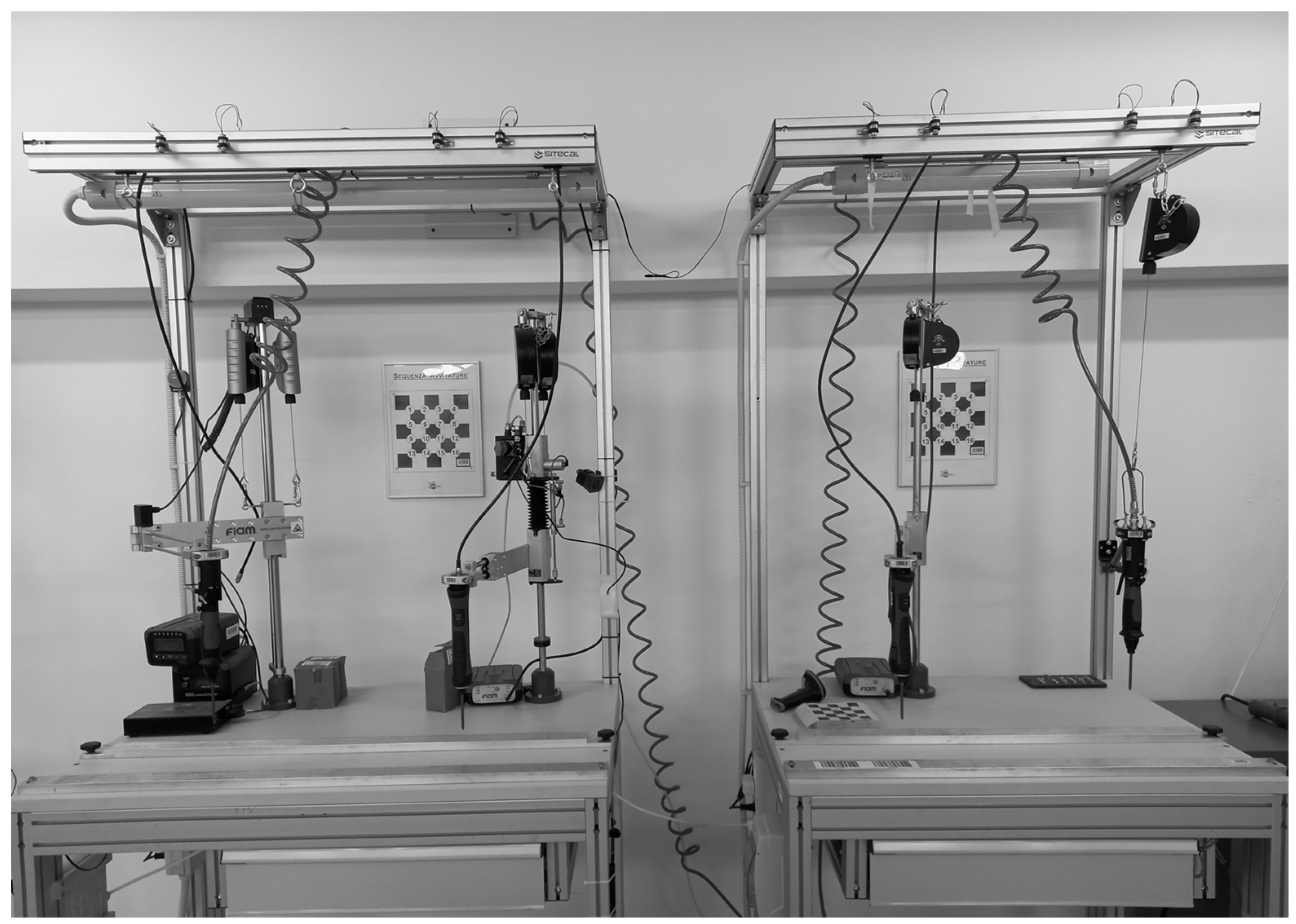
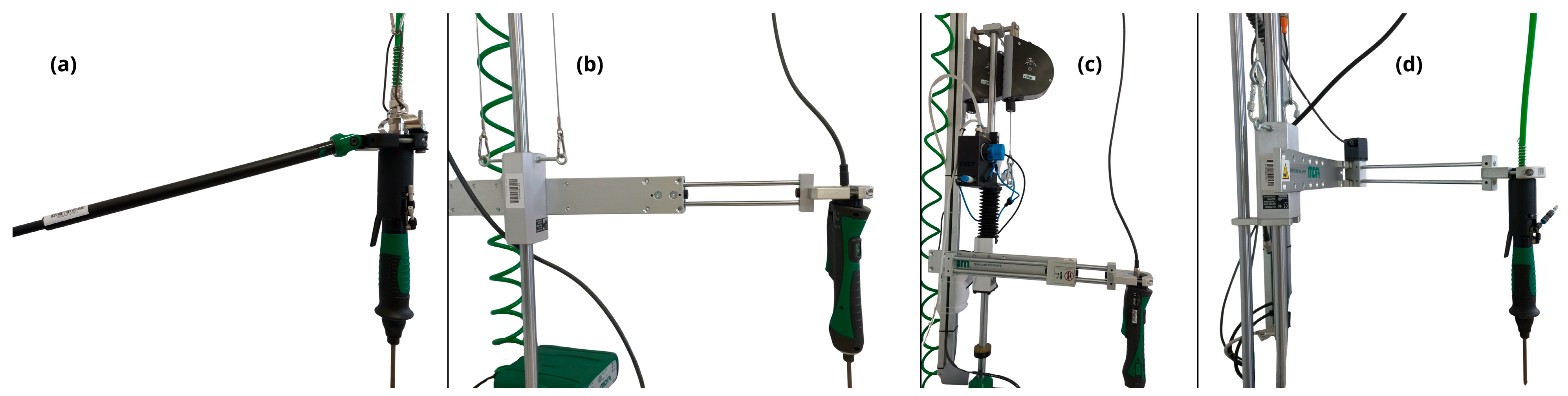
The experimental conditions were defined by the type of support arm used to equip the in-line power screwdrivers (
Figure 1 and
Figure 2):
Balanced electric/pneumatic drive screwdriver without support arm (NB);
Balanced electric/pneumatic drive screwdriver with telescopic support arm (BT);
Balanced electric/pneumatic drive screwdriver with Cartesian support arm (BC);
Balanced electric/pneumatic drive screwdriver with push-off assisted Cartesian support arm (BCP);
Balanced electric/pneumatic drive screwdriver with articulated Cartesian support arm (BCA).
All screwdrivers, workstations, and support arms were manufactured by FIAM Utensili Pneumatici S.p.A. (Vicenza, Italy).
Figure 1.
Experimental workstations, left to right: BCA, BCP, BC, BT. Uncoupling the support arm from the screwdriver in the BT workstation would provide the balance screwdriver with no support arm for the NB condition.
Figure 1.
Experimental workstations, left to right: BCA, BCP, BC, BT. Uncoupling the support arm from the screwdriver in the BT workstation would provide the balance screwdriver with no support arm for the NB condition.
Figure 2.
Support arms: BT (a), BC (b), BCP (c), BCA (d).
Figure 2.
Support arms: BT (a), BC (b), BCP (c), BCA (d).
To ensure consistency, all workstations featured a work surface set at a height of 90 cm. The initial resting position of the power tools and the location of the screw dispenser were kept identical across all setups. Furthermore, the fastening targets and the tightening sequence remained strictly constant. To minimize potential confounding factors, the order in which participants tested the five workstations was randomized.
Following an introduction and a familiarization phase with each workstation configuration, participants performed 16 fastening operations using a pneumatic drive in-line screwdriver and 16 using an electric drive in-line screwdriver for each workstation. Between conditions, the participants rested only for the time required to set up the next condition (1–3 min). This resulted in a total of 32 screwdriving tasks acquired per experimental condition. Fastening was performed using 3.5 × 20 mm cylindrical head screws driven into a 15 × 15 cm square wooden support featuring a checkerboard pattern, strictly adhering to a pre-set tightening sequence (
Figure 3). The target torque for both screwdrivers was preset to 4 Nm.
2.4. Data Acquisition
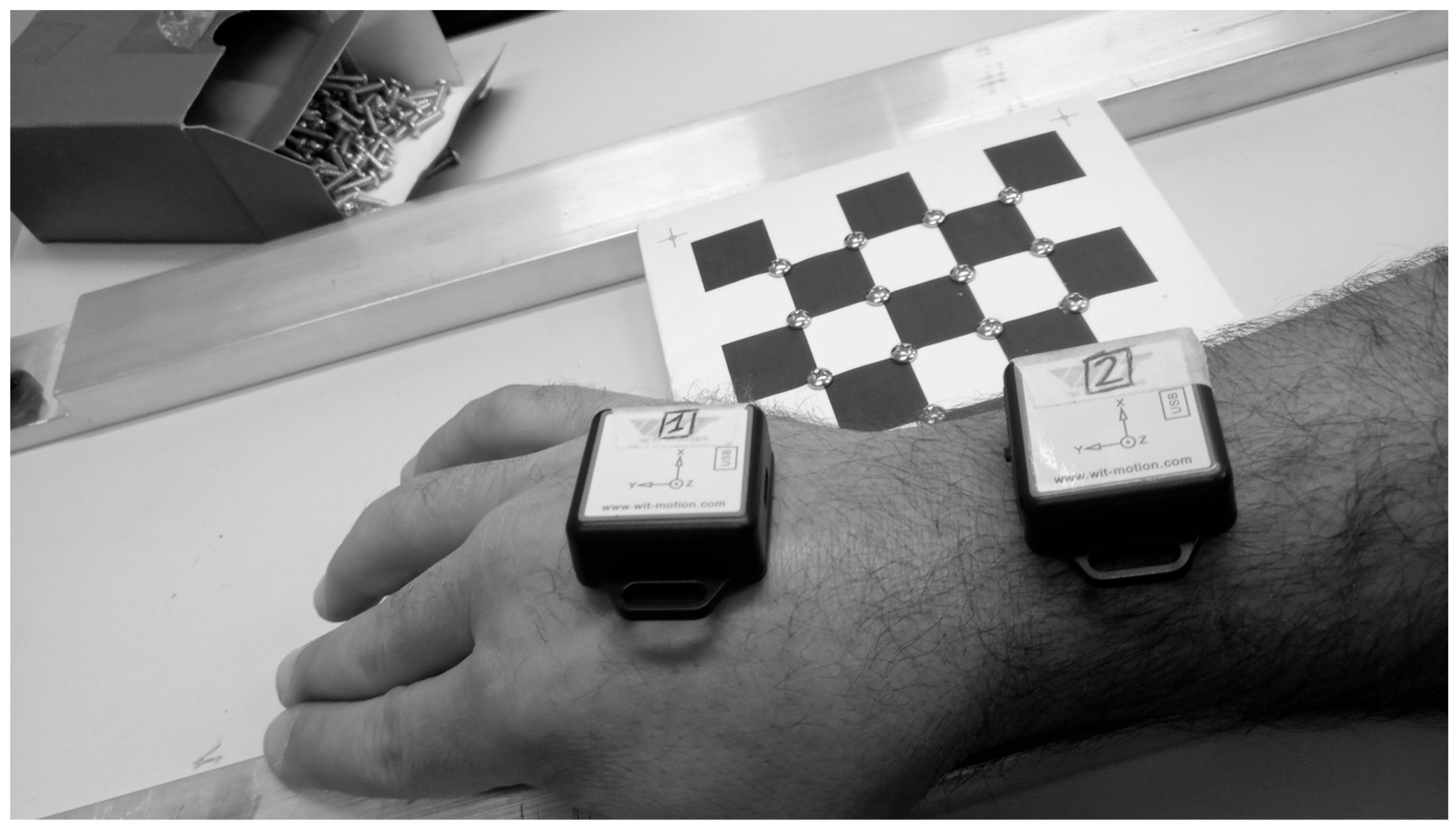
Following the calibration of the sensors’ accelerometers and gyroscopes, two IMUs (BWT901CL—WitMotion Co., Ltd., Shenzhen, China; 200 Hz) were securely placed on the participant’s right upper limb. One sensor was attached to the dorsal aspect of the hand, while the other was affixed to the posterior side of the distal radial epiphysis (
Figure 4).
Participants were then instructed to maintain a stationary, horizontal forearm while performing multiple wrist flexion-extension movements. This procedure served a dual purpose: to differentiate between the hand-mounted and forearm-mounted IMUs, and to calibrate the relative rotation of the two sensor reference frames, enabling subsequent geometrical alignment with the wrist joint’s medio-lateral axis [
29].
2.5. Data Processing
Data handling and computational procedures were performed using MATLAB R2024a (The MathWorks Inc., Natick, MA, USA). Prior to any computation or peak extraction, the temporal alignment of the kinematic signals was verified. This synchronization relied on timestamps embedded within the sensors’ internal clocks by the global clock of the acquisition PC. Ensuring precise temporal alignment was crucial for accurately computing the wrist angular velocity () as the instantaneous difference between the angular velocities recorded by the hand and forearm sensors.
Notably, no offline signal filtering was applied to the acquired kinematic data. This methodological choice was driven by two main factors: first, the IMU sensors utilize a proprietary onboard Kalman filter that intrinsically mitigates raw sensor noise; second, the tool recoil is a highly impulsive, high-frequency dynamic event. Applying a standard offline low-pass filter would risk artificially attenuating the true signal peaks, thereby underestimating the actual mechanical shock and the resulting potential load experienced by the operator.
To ensure the accurate identification of the recoil events and avoid false triggers from incidental movements, the peak values of and were manually extracted. A trained researcher visually inspected the synchronized kinematic traces for each experimental trial on-screen and hand-selected the 16 distinct peaks corresponding to the sudden tool shut-offs for each fastening operation.
2.6. Statistical Analysis
Because and represent relative variations (ratios), their interpretation relies on the statistical significance of the underlying kinematic variables. Consequently, the following interpretative constraints were applied:
is considered valid only if a statistically significant difference in is detected between the two compared workstations.
is considered valid only if statistically significant differences are observed in both and
If these significance thresholds are not met, the respective ratios are deemed non-informative.
For comparisons meeting these criteria, and were computed using the mean values of the relevant variables across all fastening operations performed by the 30 participants, effectively quantifying the magnitude of the difference between the paired workstations.
Statistical analyses were performed using STATA software (v. 16.1; StataCorp LLC, College Station, TX, USA). The dataset featured a multilevel nested structure comprising the subjects (1–30), the measured kinematic variables, the workstations (1–5), the screwdrivers (1–2), and the individual fastening operations (1–32) as the primary unit of observation.
A multilevel mixed-effects linear regression model was employed to assess whether there were statistically significant differences in each variable across the five workstation configurations. To isolate the main effect, the model was adjusted for five covariates (age, weight, height, BMI, and forearm length). These were selected as potential confounders from the subjects’ collected anthropometric data to account for inter-individual variability during the screwdriving task.
Finally, a pairwise comparison of linear marginal predictions with Sidák’s p-value adjustment was performed across the levels of the factor variable “workstation” to assess whether, and specifically which, pairs of workstations were significantly different from each other. Cohen’s d for paired data was used to calculate effect sizes for differences between workstations. The level of statistical significance was set at p < 0.05 for all tests.
3. Results
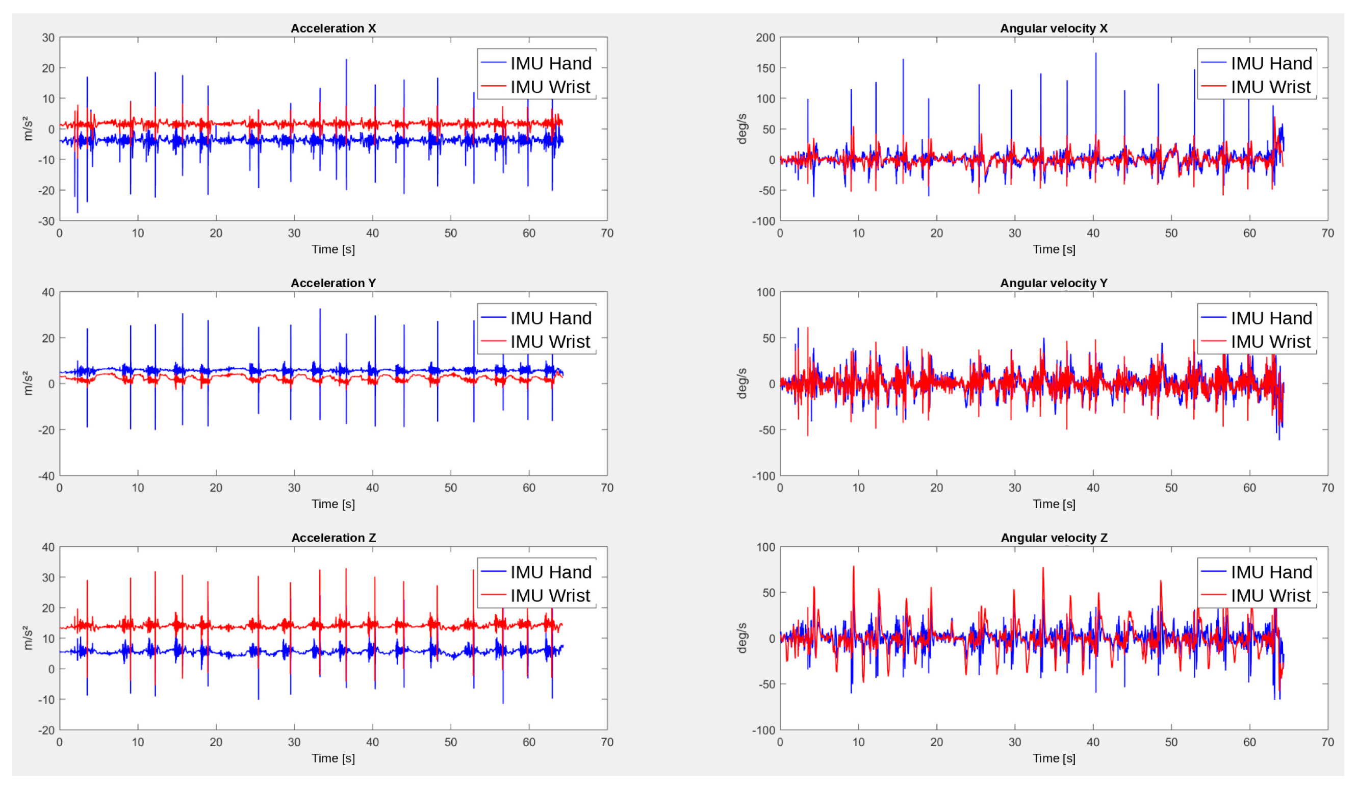
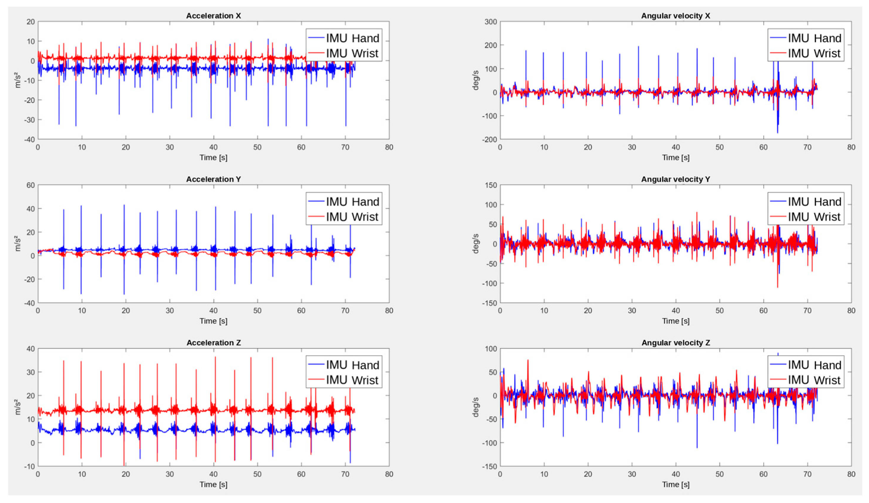
The experimental setup was able to clearly detect the peaks in angular acceleration and velocity during the screwdriving task.
Figure 5 and
Figure 6 show an example of the raw data from the condition without a support arm for the pneumatic and electric screwdrivers, respectively.
In line with previous data [
30], a pattern of torque build-up and peak appears in the extracted data, with both positive and negative accelerations, consistent with a reflexive flexion-extension movement of the hand.
3.1. Main Effects and Covariates
The multilevel mixed-effects linear regression model revealed that the workstation configuration had a strong, significant main effect on both the peak angular acceleration and the peak wrist angular velocity ( for both variables). Screwdriver type showed a significant effect for peak hand angular acceleration (). Interaction between workstation and screwdriver revealed a significant difference in the unsupported condition, favoring the pneumatic drive screwdriver ().
Regarding the included covariates, age demonstrated a statistically significant effect on the hand peak angular acceleration (), but not on the wrist peak angular velocity (). All other anthropometric covariates, including weight, height, BMI, and forearm length, yielded no statistically significant effects on either kinematic variable.
3.2. Kinematic Variables
Descriptive statistics for the kinematic variables across the five experimental workstations are summarized in
Table 2.
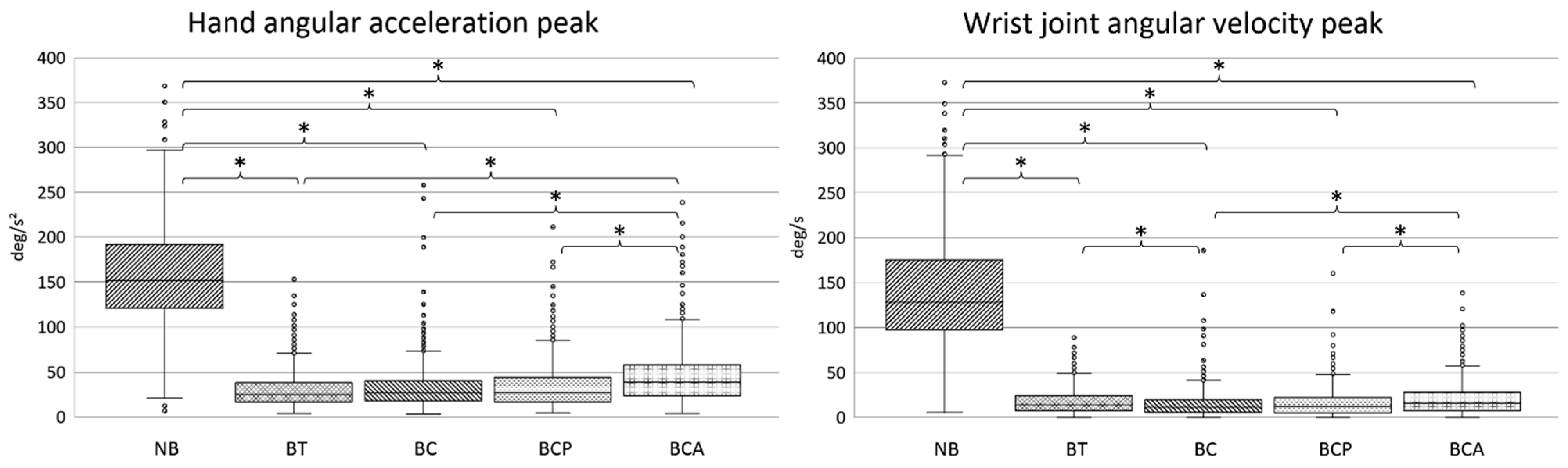
The distribution of these data, along with the statistically significant pairwise differences between configurations, is visually represented in the boxplots in
Figure 7. Notably, the workstation with no support arm exhibited the highest kinematic responses across all measured parameters.
3.3. Pairwise Comparisons and Ergonomic Efficacy
In accordance with the defined methodology, and were computed solely for workstation pairings that demonstrated statistically significant differences in their respective underlying kinematic variables.
All support arm configurations significantly reduced both and compared to the baseline workstation with no support arm (). Consequently, both and were valid and computable for these comparisons:
BT vs. NB: Reduced transmitted torque by 80.8% (), with an effect size d = −2.52, and maximum potential joint power by 97.6% () with an effect size of −2.22.
BC vs. NB: Reduced transmitted torque by 79.8% (), with an effect size d = −2.42, and maximum potential joint power by 97.8% (), with an effect size d = −2.19.
BCP vs. NB: Reduced transmitted torque by 79.2% (), with an effect size d = −2.33, and maximum potential joint power by 97.6% (), with an effect size d = −2.22.
BCA vs. NB: Reduced transmitted torque by 71.5% (), with an effect size d = −2.15, and maximum potential joint power by 95.7% (), with an effect size d = −2.13.
When comparing the performance of the different support arms against each other, distinct performance clusters emerged:
BT, BC, and BCP configurations: Pairwise comparisons among BT, BC, and BCP yielded no statistically significant differences in peak angular acceleration (). While the BC vs. BT comparison showed a significant difference in
(), the lack of significance in renders both the torque and power ratios non-informative according to the methodological constraints. These three support arms can therefore be considered equivalent in their shock mitigation efficacy. This is also supported by their respective effect sizes, ranging between −0.15 and 0.09, denoting a negligible effect.
BCA vs. BT: BCA induced significantly higher angular acceleration than the BT (), making valid: compared to the BCA, the BT configuration reduced transmitted torque by 32.6% (), with an effect size of d = 0.45. However, the difference in was not significant (); thus, the is deemed non-informative.
BCA vs. BC and BCP: The BCA configuration induced significantly higher angular acceleration and significantly higher wrist angular velocity than both the BC ( and d = 0.38 for ; and d = 0.27 for ) and the BCP ( and d = 0.37 for ; and d = 0.27 for ). Therefore, all ratios were assumed to be valid:
Compared to BCA, the BC configuration reduced transmitted torque by 29.1% () and potential joint power by 49.3% ().
Compared to BCA, the BCP configuration reduced transmitted torque by 27.0% () and potential joint power by 44.7% ().
4. Discussion
The primary aim of this study was to propose an accessible, field-ready computational methodology to quantify the reduction in mechanical shock and potential biomechanical load when comparing different screwdriving workstations. The primary aim of this pilot study was to develop and test an accessible computational methodology for the comparative characterization of recoil-induced biomechanical responses across screwdriving workstation configurations. The computational method proposed showed the potential capacity to evaluate relative reductions in both the torque transmitted to the HAC, quantified via
, and the worst-case joint power developed at the wrist, quantified via
. Crucially, this method circumvents the need for complex inverse dynamics or torque transducers, relying entirely on easily available wearable IMUs to calculate safety-oriented indices directly at the operator level. The use of wearable IMUs in this study is part of a larger push to recognize the validity of these sensors for occupational applications, including joint angle estimation, with the goal of preventing WRMSDs [
31,
32].
The methodology appears to have sufficient sensitivity to capture the significant kinematic differences between the presence and absence of a support arm in screwdriving workstations. Even without knowing the absolute values of the transmitted torque, the relative reduction is informative for decision makers who are interested in adopting torque-reducing solutions in workstations.
While not the main objective of this study, discussing differences in support arms is used to highlight a direct example and case-use of the proposed methodology. As expected, the unsupported baseline condition (NB) yielded drastically higher kinematic responses across all measured parameters. In accordance with ISO 11148-6:2012—which suggests the adoption of torque-absorbing means when exceeding the 4 Nm threshold—our data quantify the substantial benefit of such interventions. Employing any of the tested support arms (BT, BC, BCP, BCA) mitigated the transmitted torque by 71.5% to 80.8% and reduced the maximum potential wrist joint power by over 95%. These findings provide quantitative evidence for the beneficial role of support arms in relieving the operator’s wrist from the peak impacts of impulsive recoil.
Beyond the comparison of supported versus unsupported screwdriving, the methodology highlighted more subtle performance differences among the support arm designs. The workstations equipped with BT, BC, and BCP proved to be statistically equivalent in their capacity to mitigate transmitted torque and maximum potential joint power, although a marginal difference between BC and BT emerged for wrist angular velocity only. The additional push assistance given by BCP, however, is not involved in this analysis, but may be captured, for example, by the OCRA method by reducing the perceived effort in the screwing task.
Conversely, the BCA emerged as relatively less effective in mechanical shock reduction. For instance, the BC and BCP configurations reduced the transmitted torque by roughly 27–29% and nearly halved the potential joint power (44.9–49.2% reduction) compared to the BCA. This discrepancy might be attributable to the specific geometric and structural properties of the arms. The BCA features a longer, multi-jointed design having a total length fixed at 73 cm, whereas the other arms are structurally more compact and operate at shorter extensions (ranging from 36 to 69 cm). It can be hypothesized that a longer articulated geometry introduces higher structural compliance, potentially storing more elastic energy during the torque build-up phase and delivering the stored energy back into the system upon tool shut-off, resulting in a higher angular acceleration transferred to the operator’s hand. This highlights the practical usefulness of the proposed methodology, which would allow stakeholders to make an informed decision between support systems that would apparently fulfill the same function.
An important, yet often overlooked, aspect of mechanical shock transmission is the role of individual physiological differences. The multilevel mixed-effects model revealed that the operator’s age exerted a statistically significant effect on the peak angular acceleration (
) recorded at the hand. This finding is biomechanically relevant: aging can influence handgrip strength and strategy and muscular stiffness [
33], leading to differences in damping of shocks and vibrations transmitted to the HAC.
While current ISO standards primarily focus on tool-centric parameters, the previous literature has already suggested that operator-tool interaction variables play a crucial role in perceived discomfort and biomechanical load [
10,
21,
34]. The detection of an anthropometric covariate affecting shock magnitude supports the premise that evaluating mechanical perturbations directly at the operator’s HAC could be a valuable complement to traditional assessments that rely solely on the raw mechanical output measured at the tool’s handle. In this context, our operator-centric methodology would work in parallel with the tool-centric standards; if torques exceeding 4 Nm are detected and preventive measures are put in place, this methodology could potentially be used to quantify the reduction in transmitted torque and power to the operators.
While the proposed approach offers a simplified procedure for in-field ergonomic assessments, several limitations must be acknowledged. The mathematical identity allowing the estimation of torque ratios relies on the assumption of a standardized posture and a fixed Instantaneous Center of Rotation (ICR), which is necessary to guarantee a constant moment of inertia for the hand–forearm-tool system, as noted also by Lin et al. [
20]. To reduce variability in hand posture between subjects, we decided to recruit only right-handed male participants. Additionally, to ensure that the ICR remained constant between conditions, we ensured that the horizontal and vertical distance of the in-line screwdrivers was standardized with different support arms. Practitioners applying the proposed methodology must therefore ensure standardized geometry across workstations (e.g., standardized grip height, girth, and distance with different screwdrivers and support arms). Furthermore, while the Maximum Potential Load Index was adopted as a safety-oriented upper bound to prevent the underestimation of biomechanical load, it remains an upper-bound proxy rather than an absolute measure of instantaneous joint power.
Another limitation is that we manually detected the acceleration and velocity peaks. This is time-consuming and could potentially introduce bias and variability. Based on the examples in
Figure 5 and
Figure 6, however, it should be noted that the peaks are especially visible along the main axis of the countershock. A future development of the methodology here proposed could include automating the peak detection process to improve reliability. Finally, the sampling rate of the IMU used for the study was on the lower end for impulsive events, although all the recorded segments showed a full set of 16 screwdriving actions. Future studies implementing IMUs with sampling rates of 400–1000 Hz could further validate the methodology proposed. Additionally, further validation studies will be required to test whether the methodology is sound for different target torques and with different screw types and materials. Concurrent validation, employing torque transducers and/or force-measuring gloves, could also be performed.




 ,
,