Article

Nanoimprinted Polymeric Structured Surfaces for Facilitating Biofilm Formation of Beneficial Bacteria

1
DTU Nanolab, National Centre for Nano Fabrication and Characterization, Technical University of Denmark, 2800 Kongens Lyngby, Denmark
2
DTU Bioengineering, Department of Biotechnology and Biomedicine, Technical University of Denmark, 2800 Kongens Lyngby, Denmark
3
Laboratory for Nano and Quantum Technologies, Paul Scherrer Institut, 5232 Villigen, Switzerland
*
Author to whom correspondence should be addressed.
Nanomanufacturing 2024, 4(4), 202-213; https://doi.org/10.3390/nanomanufacturing4040014
Submission received: 30 September 2024 / Revised: 14 November 2024 / Accepted: 20 November 2024 / Published: 27 November 2024
(This article belongs to the Special Issue Nanoimprinting and Sustainability)

Abstract

:
Initial studies indicate that structured polymer surfaces can support the attachment and biofilm formation of bacteria and thereby provide enhanced positive effects of beneficial bacteria, for instance in biocontrol in aquacultures. In this study, we demonstrate a test platform to further explore the surface topography for bacterial attachment and biofilm growth. It is based on a cyclic olefin copolymer (COC) materials platform, and nanoimprint technology was used for the replication of microstructures. The use of nanoimprint technology ensures precise micropattern transfer, enabling easy prototyping. Further, the process parameters of the mold preparation and nanoimprinting are discussed, with the purpose of optimizing the polymer pattern profile. This study has the potential to identify promising surfaces for biofilm growth of beneficial bacteria.

1. Introduction

Biofilms are aggregates of microorganisms attached to a surface [1]. Due to the many negative effects of microbial biofilms, for instance, as the cause of persistent infections, most biofilm studies have focused on their inhibition or removal [2,3,4,5,6,7]. Researchers have investigated antibiotics, antibacterial coatings, and nano/microstructures for biofilm prevention or removal.
Beneficial properties of biofilms are less well recognized, although wastewater treatment plants largely rely on the action of biofilm-embedded microorganisms to remove or convert harmful substances [8]. Today, few industrial uses of biofilms, e.g., microbial fuel cells [9,10], fermentation [11], and biomanufacturing of chemicals, are known [12], but the inherent properties of biofilm-embedded microorganisms [13] make such systems attractive as alternatives to suspended cultures.
In the food supply system for humans, aquatic animal foods account for 15 percent of animal protein consumption [14], and aquaculture can meet the rising demand for high-quality protein foods. Aquaculture, just like any other intensive industry, is challenged by microbial infections, and sustainable infection control is a major challenge. The use of antibiotics obviously must be reduced to limit the development of antibiotic resistance [15]. Fish vaccine has been quite successful in the salmon industry; however, the vaccine cannot be administered to the fish larvae [16]. Therefore, additional ways of infection control are needed.
Bacteria from the roseobacter group, such as Phaeobacter species, have been studied as a potential probiotic in marine larval rearing, and their ability to reduce pathogens is, in part, caused by the production of an antimicrobial secondary metabolite called tropodithietic acid (TDA) [17]. In some TDA-producing roseobacters, the production of TDA is facilitated when the bacterium attaches and forms biofilm as compared to the planktonic growth [18].
A few studies describe how surfaces can facilitate biofilm formation. For example, flax fibre-reinforced biocomposites [19] were studied for marine bacterial biofilm formation, and the physicochemical properties of biocomposites for bacterial attachment were discussed. Many studies reveal the important factors relevant to biofilm formation [20,21,22], among them being substrate surface roughness, which can be either random or of a defined surface topography [23]. Surface topography with regular structure can be produced via replication from a mold into a suitable material. This production method also has the advantage that different dimensions and structures can easily be compared, and structures can readily be selected for the most effective biosynthesis of TDA by the attached bacteria.
Bacterial biofilm growth on a structured COC chip was investigated by Droumpali et al. [24], who used injection molding to replicate the micropatterns. COC is a common thermoplastic polymer with good biocompatibility and can be mass-produced. COC also stands out because of its low autofluorescence and good optical property for bacteria inspection [25]. COC has great potential for large-scale production and is known to have good demolding properties compared to polystyrene (PS). Injection molding of micropatterns requires considerable energy, and its large-scale production benefits are unnecessary for small-scale academic studies. Additionally, it is not easy to change the pattern design, as the mold is normally made of metal, requiring the sacrifice of the Si master for electroplating. Roll-to-roll extrusion coating is another large-scale fabrication method in the industry with a capacity to produce up to 60 m of replicated polymer foil per minute [26]. However, again, prototyping might be difficult in such large-scale production. Therefore, from a sustainability perspective, thermal nanoimprint lithography (NIL, also hot embossing) offers polymer micropattern replication with sufficient throughput, low energy consumption, and low cost for rapid prototyping. The hypothesis that we test in this work is that nanoimprinting can be used for the rapid prototyping of well-defined microstructured surfaces that enable biofilm formation of beneficial bacteria.

2. Materials and Methods

2.1. Structure Design

Hexagons have been favored by nature, as evidenced by structures such as honeycombs. Notably, hexagonal patterns have already been employed for studies of bacterial attachment and growth [27]. From the fabrication point of view, with hexagons, patterns are more equally distributed regarding the gaps in between, and 90° edges or corners that are often detrimental to the molding step are avoided. In this study, hexagonal pillars and pits structures were used to investigate bacterial growth and production, with reference to flat unstructured surfaces. The hexagonal pits and pillars had a side length of 5 µm, and the gap between each structure was varied for 2, 5, 10, 20, and 30 µm. The heights of the structure were either 5 or 10 µm. The patterns were designed using CleWin5 software (WieWeb software, Hengelo, The Netherlands).

2.2. Nanoimprint Master Fabrication

2.2.1. UV Lithography

Micropatterns were originated on 150 mm diameter <100> single-sided polished silicon wafers with a thickness of 675 ± 20 µm (Siegert Wafer GmbH, Aachen, Germany), see Figure 1. A layer of 1.5 µm photoresist (AZ5214E) was applied using a spin coater (Gamma 2M cluster, Süss MicroTec, Garching, Germany). The design was transferred to the photoresist using a maskless aligner (Heidelberg Instruments MLA150 Maskless Aligner, Heidelberg, Germany) through an 8W laser at a dose of 65 mJ/cm2 emitted at 375 nm. The development of samples was performed for 60 s in a tetramethylammonium hydroxide (TMAH)-based solution (AZ 726 MIF in 2.38% TMAH water solution) to develop the pattern (Süss MicroTec Gamma 2M developer, s/n GAMMA-000233).

2.2.2. Si Etching and Smoothing

Approximately 5 and 10 µm of Si was etched by deep reactive ion etching (DRIE) (SPTS Advanced Deep Reactive Ion Etching Pegasus, England). An inner coil and an outer coil with 13.56 MHz RF generators produced plasma, where the maximum power was 5 kW. A deposit–remove–etch multiple times (DREM) process, 1kW power with 55 or 110 cycles, was used. An oxygen plasma ashing process removed the remaining photoresist. For smoothing the scallops, a layer of ~600 nm of SiO2 was grown by wet oxidation in a furnace with O2 gas at 1100 °C for 70 min. Subsequently, an annealing step of 20 min in N2 gas was carried out. Before starting the furnace, a standard RCA cleaning step was used to clean the samples from any residuals. After the SiO2 growth, the silicon master was dipped in a buffered hydro-fluoric acid (BHF) bath with a wetting agent, featuring a SiO2 etch rate of 75–80 nm/min, for 5–7 min to remove the oxide.

2.2.3. Anti-Sticking Layer Coating

For better anti-sticking properties, the produced Si mold was coated with a self-assembled monolayer from the precursor perfluorodecyltrichlorosilane (FDTS) (Applied Microstructures Inc. MVD 100 Molecular Vapour Deposition System).

2.3. Nanoimprint

2.3.1. Polymer Material

250 µm thick COC foils were fabricated by the roll-to-roll extrusion method (Inmold, Nivå, Denmark).

2.3.2. Nanoimprint Parameters

A CNI v3 machine (Nil Technology ApS (NILT), Kongens Lyngby, Denmark) was used to perform the imprinting. To prevent sticking, a Teflon foil was placed on the substrate. The micropatterned Si wafer mold was positioned with the patterned side facing up. A COC foil was placed on the mold, followed by another Teflon foil. The lid of the CNI machine was closed and sealed by four screws in each corner.
The process parameters were adjusted in the CNI v3 Process Window (see Table 1). For all imprints, the process started with applying vacuum at around 200 mbar and pressure at 1 bar. Then, the substrate was heated up with a 20 min ramping-up process, and then the substrate was heated to the desired imprint temperature. When it reached the set imprint temperature, the applied pressure was increased to 6 bar and was held for 20 min. A ramped cooling process cooled down the substrate until the set demold temperature, and the pressure was released. The varied process parameters are as follows.

2.4. Characterization of Polymer Surfaces

2.4.1. Laser Confocal Microscope

The micropatterns on the COC surfaces were inspected by a 404 nm laser scanning confocal microscope (KEYENCE VK-X 3000, Mechelen, Belgium). Three-dimensional topography of the surfaces was formed, and the heights of pillars/pits were measured.

2.4.2. SEM

For characterizing the samples with different topographies, scanning electron microscope (SEM) images were obtained using a Zeiss Supra VP 40 instrument (Carl Zeiss AG, Jena, Germany). The accelerating voltage was either 3 or 5 kV. SmartSEMsoftware 6.0 (Carl Zeiss AG, Jena, Germany) on the microscope was used for imaging and analysis.

2.5. Bacterial Assays

2.5.1. Sample Preparation

The micropatterned COC foils were cut into 5 × 5 mm squares. To avoid direct contact of the tweezer used to remove the surfaces from the bacterial culture and to turn the COC surface upside down, the squares were attached to a carrier. This carrier design features a 5 × 5 mm square with a 3 × 1.5 mm handle. On the backside of the carrier, sample IDs were sculpted for easy differentiation, and additional sculpted lines were made on the handle part to prevent slipperiness when using tweezers. Flat polymethyl methacrylate (PMMA) sheets of 5 mm thickness (CRYLON 610, Polycasa, Belgium) were cut into the carrier’s shape and marked by a CO2 laser cutting machine (EpiLog 8000 laser system). The cutting speed was 100%, and cutting power was 40% and 25% for cutting and patterning. Attachment was carried out by biocompatible double-sided glue (Adhesive Research ARseal 94119).
The surfaces were sterilized by submerging them in 0.5% (vol/vol) hypochlorite solution for 2 h, followed by rinsing with deionized water and drying. The sterilized surfaces were then kept in Petri dishes.

2.5.2. Bacterial Strains and Culture Conditions

The bacterial strain Phaeobacter piscinae S26, isolated from an algae, Tetraselmis suecica, used in aquaculture [28], was used in this study. The strain was cultured in 3% (w/v) Instant Ocean (IO, Mini Zoo) with 0.3% (w/v) Casamino Acids (Bacto™), 0.3% (w/v) HEPES (Fisher Bioreagents (Pittsburgh, PA, USA)), and 0.2% (w/v) Glucose (Merck), adjusting the pH to 6.8–7. Cultures were incubated at 25 °C with shaking at 200 rpm for overnight cultures and at 140 rpm for biofilm assays. Stock cultures were kept at −80 °C in 18% (vol/vol) glycerol (VWR).

2.5.3. Biofilm Formation Assay

Stock cultures were streaked onto Marine Agar (MA, Difco 2216; 55.1 g/L), and single colonies were used to prepare precultures that were grown as mentioned above for 16 h. Outgrown cultures were diluted 1000-fold in fresh IOCG. The bacterial cultures were transferred into a Nunclon™ 96-round bottom microtiter plate containing the surfaces mentioned above and incubated for 24 h. After incubation, surfaces were rinsed with 3% sterile IO to remove any planktonic cells and transferred to a solution of 2.5% (vol/vol) glutaraldehyde (Merck) in 3% IO buffer overnight at 5 °C to start the fixation.

2.5.4. Bacterial Characterization

SEM was used to observe the bacterial growth on surfaces. After the initial fixation, the samples were rinsed twice in milliQ H2O for 5 min each time. Samples were dehydrated with an ethanol series of 50%, 70%, and 95% for 5 min each time. Samples were further dehydrated twice with 100% ethanol for 5 min each time. After dehydration, samples were placed in a critical point dryer (Leica EM CPD300, Wetzlar, Germany) and dried in supercritical CO2. Samples were placed in a sputter coater (Leica EM ACE600, Germany), and a thin layer (around 10 nm) of platinum was deposited on the bacterial samples. A SEM (FEI Quanta FEG 200, Lausanne, Switzerland) operating at 10 kV was used to observe the location and shape of the bacteria on surfaces.

3. Results

3.1. Mold Characterization

For nanoimprinting, the profile of the structure’s sidewall is crucial, especially for fabricating a perfect inverse tone of the mold relief. The sidewall angle and the roughness of the mold are key factors for a successful demolding process. Ideally, the sidewall profile should be vertical or have a draft angle (positive inclination) of 5°. This will reduce friction and facilitate air penetration within the microstructures. Surface roughness on the sidewall can introduce friction, potentially trapping the structures if the surface is excessively rough. Therefore, specific steps were incorporated into the process flow to create straight and smooth sidewalls.
By replacing the conventional deep reactive-ion etching (DRIE) process (Bosch process) with the DREM process (deposit–remove–etch multistep) [29], the surface roughness was greatly decreased. It is well known that scallops are the inherent consequences of the conventional DRIE process, and the scallops’ size was optimized through a precise control of the etching step in the DREM process. As shown in Figure 2a, the surface roughness on the side wall is reduced when compared with the samples using the conventional DRIE process. However, the roughness can be further decreased by thermal oxide growth [30]. In Figure 2b, the oxide had grown on the Si surfaces, completely oxidizing the most protruding parts of the scallops and expanding the volume compared to the pure Si surfaces. As shown in Figure 2c, the silicon oxide was removed, and a smooth surface was achieved.

3.2. Characterization of Polymer Foils

3.2.1. Fabricated Almost-Perfect Print

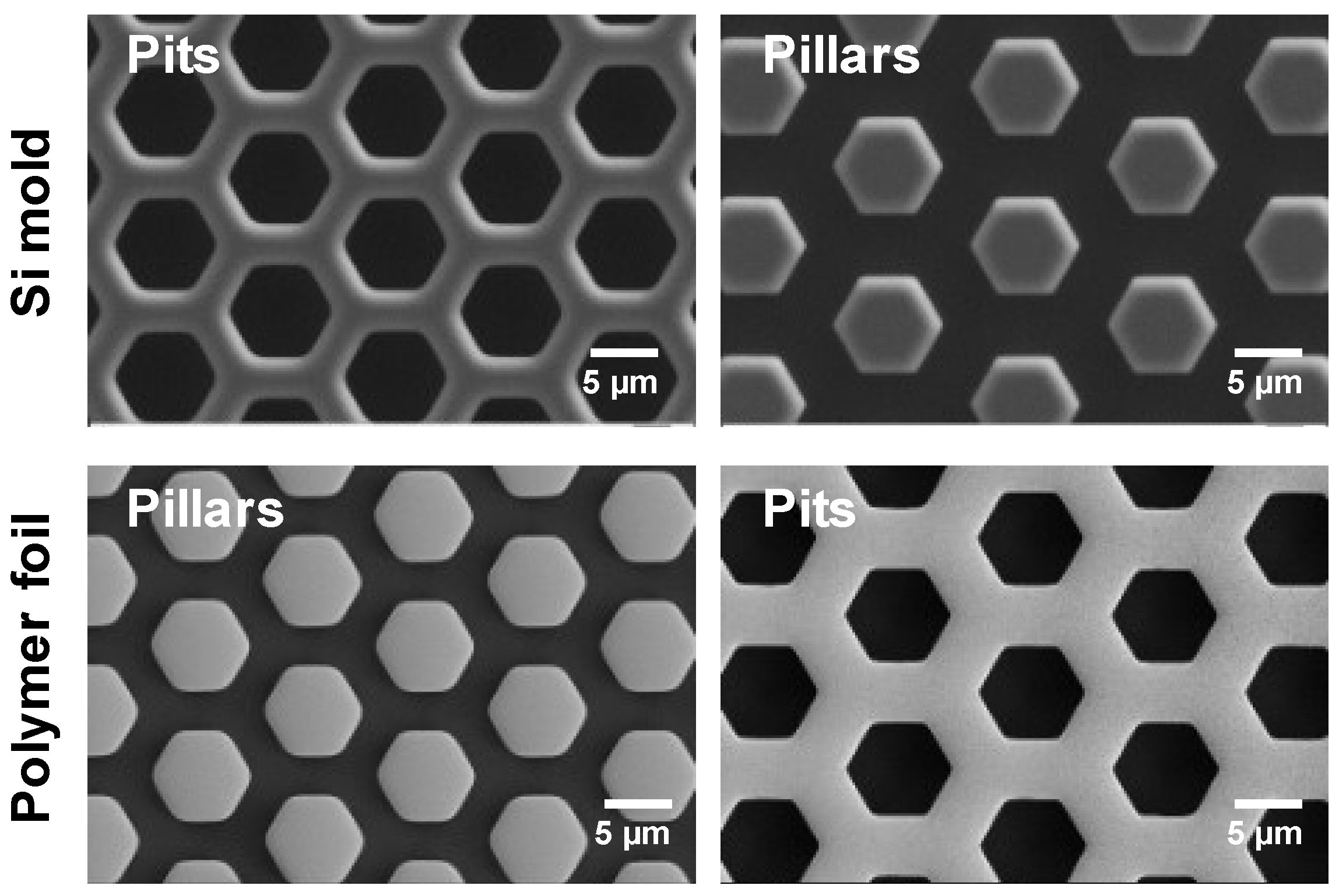
Nanoimprint technology allows us to replicate the patterns from the Si mold to polymer foils. This thermal process applies pressure and heat, causing the polymer to flow and fill in the gaps of the mold. This process can produce the shape as the reverse polarity of the mold. By tuning the parameters in the nanoimprint tool, including temperature, time, pressure, and demold method, an almost-perfect print was produced. Here in Figure 3, with a top view of the hexagonal pits and pillars, it can be seen that there is almost no difference between the structures on the Si mold and the replicated polymer foil. The shape and gaps of the structures on the polymer foil remained consistent with the original mold. This consistency indicates that the imprinting and demolding processes were optimal.
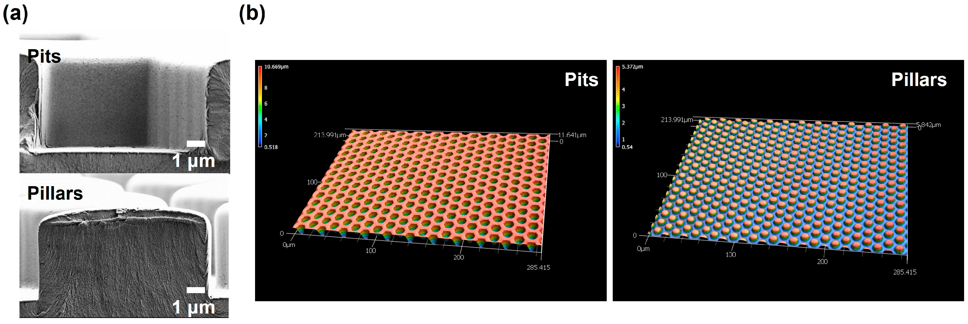
For a clearer inspection, close-up SEM micrographs were captured in the cross-sectional view (Figure 4). At higher magnification, straight and smooth side walls can be observed on COC microstructures. The measured heights revealed that the pit had a height of 5.4 µm, while the pillar was 4.9 µm deep. Different samples with varied heights were investigated by the optical profilometer. The optical profilometer image of microstructures also indicated a pit and pillar height of ~10 and ~5 µm.

3.2.2. Failure Modes

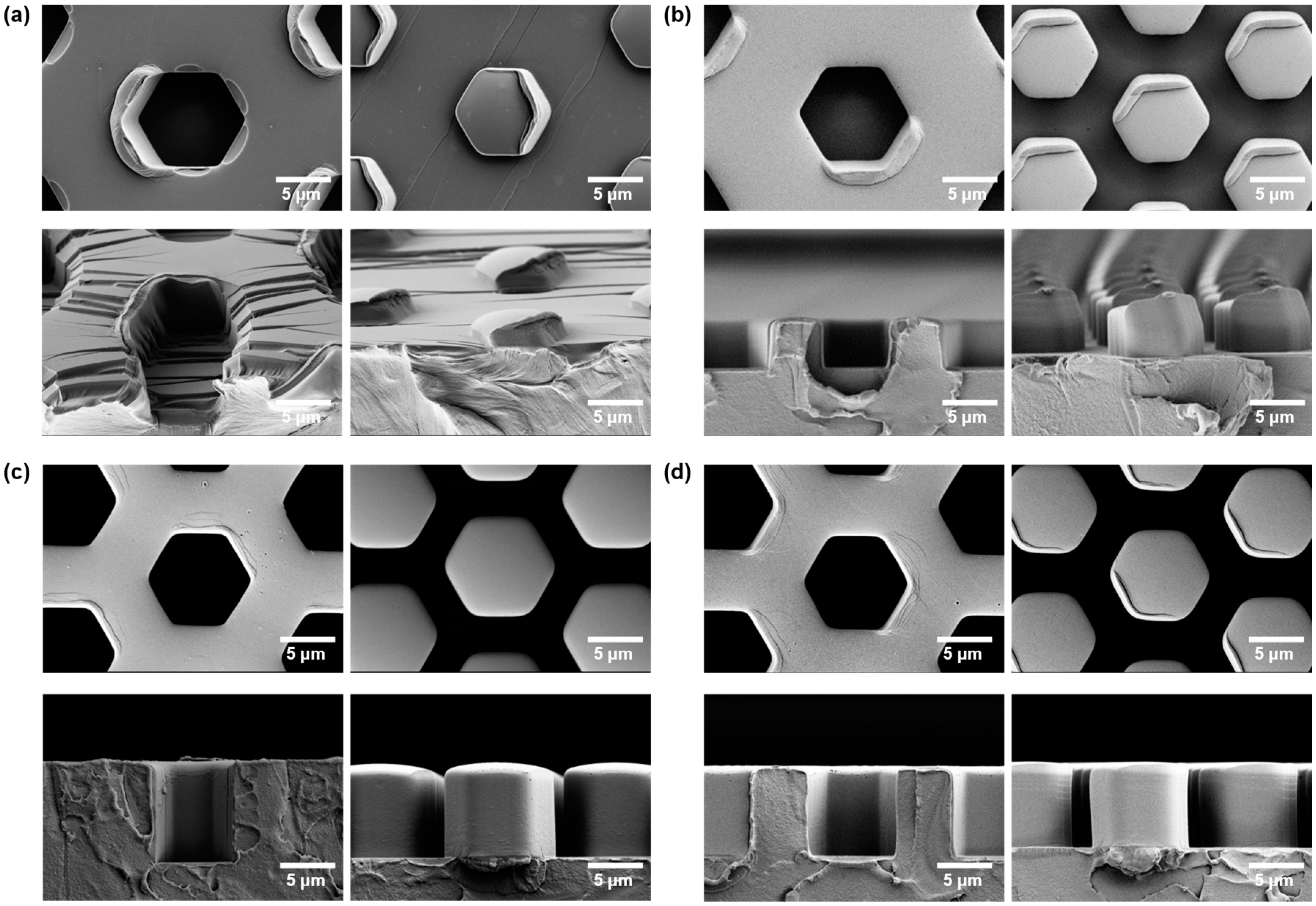
In thermal NIL, the temperature of imprinting and demolding plays a crucial role [31,32,33]. Due to the vertical sidewalls of our molds, both adhesion and friction must be considered. Low adhesion is required to separate the molded polymer from the mold. Low friction enables the sliding of the sidewalls during separation. While adhesion often causes ripping of entire structures, high friction might cause deformation and forming of rims at locations with high local strain. To select an appropriate temperature for thermoplastic materials, glass transition temperature (Tg) can be taken as a reference. Tg is determined by heating up the polymer until it reaches a viscoelastic state. When the temperature is below Tg, the polymer remains hard and glassy, and while above, it becomes viscous and able to flow. Typically, imprint temperatures are chosen to be 50–70 °C higher than Tg, and at the same time, the demolding temperatures are set to be 20 °C lower than Tg [34]. This selection range was a great help in the design of the experiment. If the imprint temperature is not sufficiently high, the polymer will not be able to flow and fill the cavity of the mold as shown in Figure 5a. Ensuring the right temperature conditions is essential for successful nanoimprint processes.
The demolding step appears to be crucial for avoiding polymer deformation [35]. Figure 5b illustrates the peel demolding at room temperature. However, during cooling below Tg, the hardened polymer undergoes shrinkage because of the mismatch in thermal expansion coefficients between the silicon mold (2.8 × 10⁻⁶/°C) and the COC polymer (0.7 × 10⁻⁴/°C) by almost a factor of ~25, resulting in a growing local strain [36,37,38]. While demolding at a temperature too close to Tg causes distortion due to the polymer’s softness, demolding at room temperature causes shrinkage of the polymer within the mold, both locally (individual structures) and globally (entire mold).
We found that demolding at different temperatures required different demolding forces, as also observed by [39,40]. An optimal range lies near the glass transition temperature (Tg), where less force is required and where less shrinkage in the polymer is expected, thus minimizing damage to the structures. In Figure 5c the structures perfectly replicated the shape of the mold, and only a few defects can be seen on the pit edges. This indicates that demolding at the appropriate temperature can effectively preserve the original structures.
Since demolding at temperatures close to Tg is a compromise that does not often result in structures without damage to the rims, demolding can be facilitated by a range of measures. Therefore, auxiliary processes were investigated to ease demolding after cooling the samples to room temperature. Two common approaches were explored to reduce adhesion, distortion, and damage to the rims, as shown in Figure 5d. Injecting a purge gas (nitrogen) into the interface between the polymer and the mold reduces adhesion and facilitates separation by cooling the interface. Another approach is soaking the samples with deionized water as a lubricant to aid separation. However, even there, defects may still be present on the top rims, and further optimization is necessary to minimize these issues. In [41], cooling below by liquid nitrogen made the polymer rigid enough so that high aspect ratio structures could be demolded.

3.3. Bacterial Growth

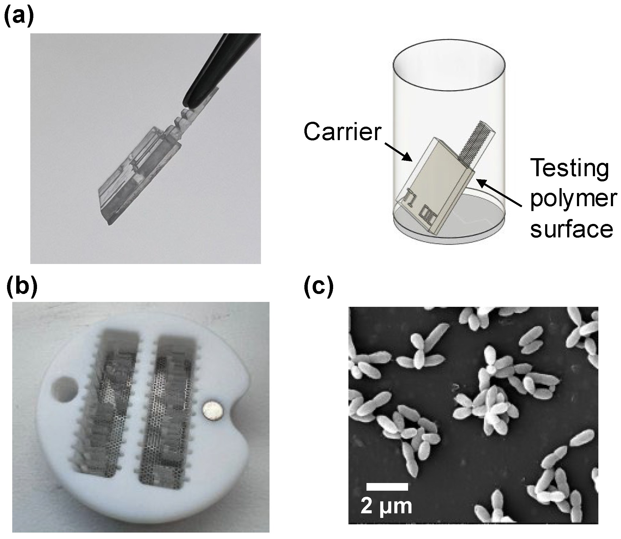
Carriers made of PMMA were created for distinguishing and manipulating polymer samples. After attaching the testing COC polymer samples to carriers, the carriers were placed into a well plate. It is crucial to make sure that bacterial settlement is not the result of gravity effects. To achieve this, the front side of the carriers—where the polymer surfaces are located—is positioned facing downward as illustrated in Figure 6a.
SEM requires the samples to be dried due to the high vacuum needed for imaging. However, conventional air-drying typically causes shape deformation and structure collapse in biological samples. To preserve the surface details of bacteria, a critical point dryer was employed. As shown in Figure 6b, a batch of samples was placed in the container for the critical point dryer, separated by cover glasses. Figure 6c shows the SEM image of bacteria. SEM micrographs enabled visualization of the bacterial growth on the flat COC surfaces as a preliminary experiment. After dehydration, the bacterial structure remained complete, and the bacterial morphology was effectively preserved.
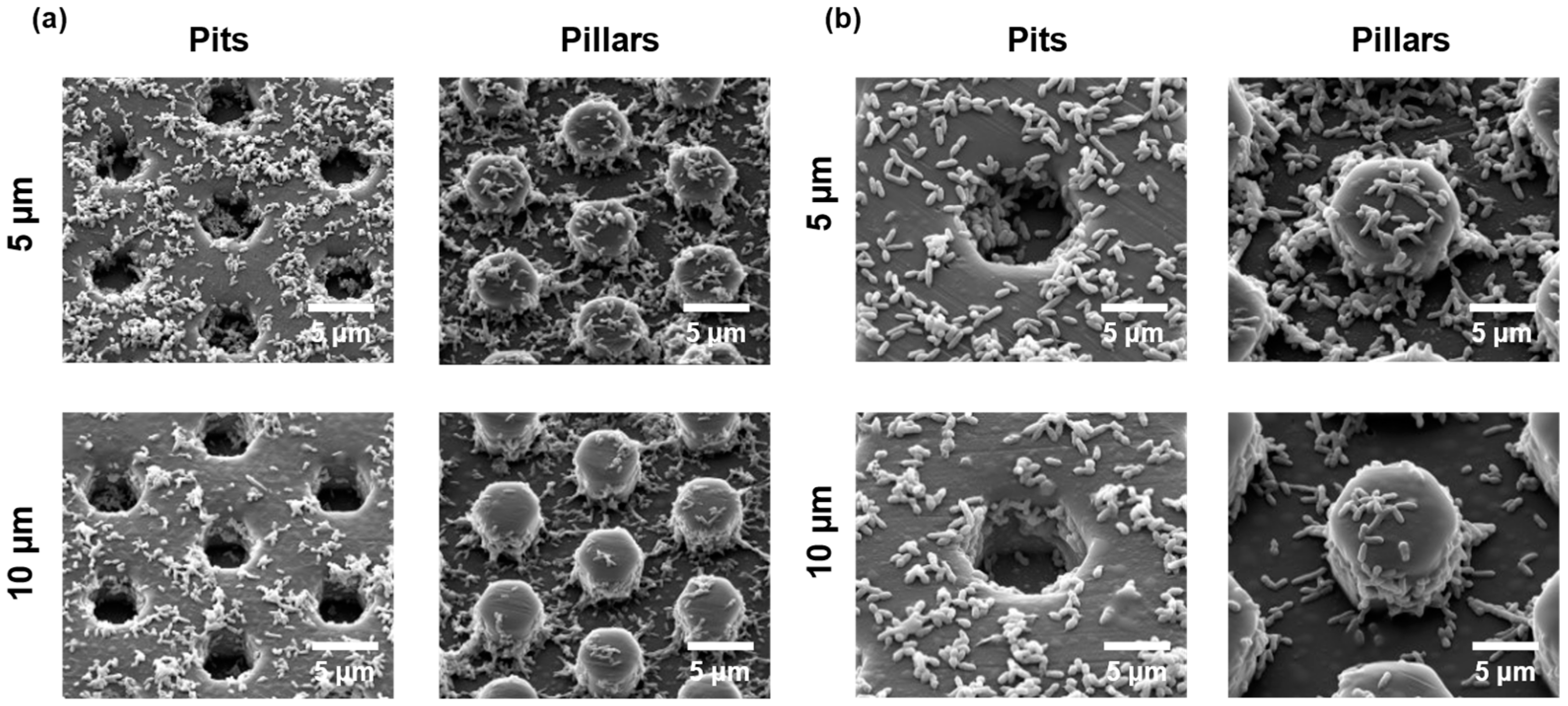
To inspect the bacterial growth on the test platform, bacteria were cultured on the microstructured COC surfaces. After culturing for 24 h, bacteria were fixed and dehydrated, and then SEM micrographs were captured. The size of a single microorganism is around 2–4 µm long and 0.5–1 µm wide, while a rosette typically spans about 5–10 µm [42]. The side length of the hexagonal structure is 5 µm and is thus comparable to the sizes of rosettes formed by bacteria. The size and gap of the structure were designed and fabricated to accommodate the rosettes. As shown in Figure 7, the carrier test platform supported bacterial growth and allowed visualization of the attached bacteria. Both single cells and rosette-forming bacteria were observed in these early-stage cultures.

4. Discussion

4.1. Nanoimprinting

For a potential large-scale production, micropatterns were fabricated on a Si wafer and subsequently replicated to polymer foil using nanoimprint techniques. While nanoimprint offers a rapid and efficient method for polymer pattern replication, precise process parameter control is crucial to achieve near-perfect replication. In this study, we explored the impact of mold conditions and imprint parameters. Key factors included mold roughness, sidewall angles, imprint temperature, and demolding methods. By fine-tuning these parameters, defects and deformations can be minimized [43]. Additionally, trade-offs such as balancing the low pressure with longer holding time, which is also a possible advantage of nanoimprinting [34]. Demolding techniques, including demolding at high temperature and the use of gas or liquid assistance, play a critical role in producing high-quality replicates. Optimal results were obtained when demolding occurred around Tg. Overall, nanoimprint technology offers a sustainable and straightforward approach for creating micropatterned polymer foils for prototyping, with a potential in further investigation of bacterial growth.

4.2. Bacterial Growth

The carrier test platform supported bacterial growth, and SEM allowed characterization of the bacterial morphology. From the SEM micrographs, it is apparent that critical point drying preserved the bacterial morphology. Droumpali et al. [24] studied the growth of Phaeobacter on the hexagonal microstructure with different polarities and also measured the production of the antimicrobial molecule, TDA. In future studies, we will employ the test platform to investigate how heights and gaps of micropatterns will influence bacterial attachment and biofilm formation of potential probiotic marine bacteria. This study already provides valuable insights for identifying promising microstructures conducive to the attachment of marine bacteria.

Author Contributions

Y.L.: investigation, formal analysis, data curation, writing original draft, writing—review and editing, visualization. X.F.-F.: investigation, writing—review and editing. C.S.: methodology, supervision, resources, writing—review and editing. P.K.: conceptualization, methodology, resources, writing—review and editing, supervision, funding acquisition. H.S.: resources, writing—review and editing. L.G.: conceptualization, methodology, validation, resources, writing—review and editing, supervision, funding acquisition. R.T.: conceptualization, methodology, resources, supervision, validation, writing—original draft preparation, writing—review and editing, visualization, project administration, funding acquisition. All authors have read and agreed to the published version of the manuscript.

Funding

This research was funded by the Novo Nordisk Foundation “Exploratory Interdisciplinary Synergy Programme 2021” with grant #: NNF21OC0070817 for the project “R2R fabrication of pro-bacterial surfaces (R2R ProBac)”. LG was also supported by a grant from the Danish National Research Foundation [DNRF137].

Data Availability Statement

All the micrographs can be found at https://figshare.com/s/2c6640c83b99e6af4e83 (accessed on 19 November 2024).

Acknowledgments

The authors acknowledge technical support from cleanroom staff members and access to the cleanroom nanofabrication facility at DTU Nanolab.

Conflicts of Interest

The authors declare no conflicts of interest.

References

  1. Vert, M.; Doi, Y.; Hellwich, K.-H.; Hess, M.; Hodge, P.; Kubisa, P.; Rinaudo, M.; Schué, F. Terminology for biorelated polymers and applications (IUPAC Recommendations 2012). Pure Appl. Chem. 2012, 84, 377–410. [Google Scholar] [CrossRef]
  2. Xu, L.-C.; Siedlecki, C.A. Submicron-textured biomaterial surface reduces staphylococcal bacterial adhesion and biofilm formation. Acta Biomater. 2012, 8, 72–81. [Google Scholar] [CrossRef] [PubMed]
  3. Cloutier, M.; Mantovani, D.; Rosei, F. Antibacterial Coatings: Challenges, Perspectives, and Opportunities. Trends Biotechnol. 2015, 33, 637–652. [Google Scholar] [CrossRef] [PubMed]
  4. Hsu, L.C.; Fang, J.; Borca-Tasciuc, D.A.; Worobo, R.W.; Moraru, C.I. Effect of Micro- and Nanoscale Topography on the Adhesion of Bacterial Cells to Solid Surfaces. Appl. Environ. Microbiol. 2013, 79, 2703–2712. [Google Scholar] [CrossRef] [PubMed]
  5. Ge, X.; Leng, Y.; Lu, X.; Ren, F.; Wang, K.; Ding, Y.; Yang, M. Bacterial Responses to Periodic Micropillar Array. J. Biomed. Mater. Res. Part A 2015, 103, 384–396. [Google Scholar] [CrossRef] [PubMed]
  6. Ghilini, F.; Pissinis, D.E.; Miñán, A.G.; Schilardi, P.L.; Diaz, C. How Functionalized Surfaces Can Inhibit Bacterial Adhesion and Viability. ACS Biomater. Sci. Eng. 2019, 5, 4920–4936. [Google Scholar] [CrossRef] [PubMed]
  7. Linklater, D.P.; Baulin, V.A.; Juodkazis, S.; Crawford, R.J.; Stoodley, P.; Ivanova, E.P. Mechano-bactericidal actions of nanostructured surfaces. Nat. Rev. Microbiol. 2021, 19, 8–22. [Google Scholar] [CrossRef]
  8. Shah, M.P. Bioremediation-Waste Water Treatment. J. Bioremediation Biodegrad. 2018, 9, 427. [Google Scholar] [CrossRef]
  9. Gude, V.G. Wastewater treatment in microbial fuel cells—An overview. J. Clean. Prod. 2016, 122, 287–307. [Google Scholar] [CrossRef]
  10. Kiran, V.; Gaur, B. Microbial fuel cell: Technology for harvesting energy from biomass. Rev. Chem. Eng. 2013, 29, 189–203. [Google Scholar] [CrossRef]
  11. Ercan, D.; Demirci, A. Current and future trends for biofilm reactors for fermentation processes. Crit. Rev. Biotechnol. 2015, 35, 1–14. [Google Scholar] [CrossRef]
  12. Jiang, Y.; Liu, Y.; Zhang, X.; Gao, H.; Mou, L.; Wu, M.; Zhang, W.; Xin, F.; Jiang, M. Biofilm application in the microbial biochemicals production process. Biotechnol. Adv. 2021, 48, 107724. [Google Scholar] [CrossRef] [PubMed]
  13. Hall-Stoodley, L.; Costerton, J.W.; Stoodley, P. Bacterial biofilms: From the Natural environment to infectious diseases. Nat. Rev. Microbiol. 2004, 2, 95–108. [Google Scholar] [CrossRef] [PubMed]
  14. Food and Agriculture Organization of the United Nations. The State of World Fisheries and Aquaculture—2006; Food and Agriculture Organization of the United Nations: Rome, Italy, 2007; Available online: https://openknowledge.fao.org/items/b4669c98-6f0c-4553-91d6-1ea6646a9b02 (accessed on 19 November 2024).
  15. Defoirdt, T.; Sorgeloos, P.; Bossier, P. Alternatives to antibiotics for the control of bacterial disease in aquaculture. Curr. Opin. Microbiol. 2011, 14, 251–258. [Google Scholar] [CrossRef] [PubMed]
  16. Sommerset, I.; Krossøy, B.; Biering, E.; Frost, P. Vaccines for fish in aquaculture. Expert Rev. Vaccines 2005, 4, 89–101. [Google Scholar] [CrossRef]
  17. Brock, N.L.; Nikolay, A.; Dickschat, J.S. Biosynthesis of the antibiotic tropodithietic acid by the marine bacterium Phaeobacter inhibens. Chem. Commun. 2014, 50, 5487–5489. [Google Scholar] [CrossRef]
  18. D’Alvise, P.W.; Magdenoska, O.; Melchiorsen, J.; Nielsen, K.F.; Gram, L. Biofilm formation and antibiotic production in Ruegeria mobilis are influenced by intracellular concentrations of cyclic dimeric guanosinmonophosphate: C-di-GMP signalling in Ruegeria mobilis. Environ. Microbiol. 2014, 16, 1252–1266. [Google Scholar] [CrossRef]
  19. Fruleux, T.; Sauleau, P.; Caudal, F.; Champion, M.; Chauvin, L.; Castro, M.; Le Duigou, A. Marine biofilm formation on flax fibre reinforced biocomposites. Biofouling 2024, 40, 415–430. [Google Scholar] [CrossRef]
  20. De-La-Pinta, I.; Cobos, M.; Ibarretxe, J.; Montoya, E.; Eraso, E.; Guraya, T.; Quindós, G. Effect of biomaterials hydrophobicity and roughness on biofilm development. J. Mater. Sci. Mater. Med. 2019, 30, 77. [Google Scholar] [CrossRef]
  21. Zhang, X.; Wang, L.; Levänen, E. Superhydrophobic surfaces for the reduction of bacterial adhesion. RSC Adv. 2013, 3, 12003–12020. [Google Scholar] [CrossRef]
  22. Carniello, V.; Peterson, B.W.; van der Mei, H.C.; Busscher, H.J. Physico-chemistry from initial bacterial adhesion to surface-programmed biofilm growth. Adv. Colloid Interface Sci. 2018, 261, 1–14. [Google Scholar] [CrossRef]
  23. Yang, K.; Shi, J.; Wang, L.; Chen, Y.; Liang, C.; Yang, L.; Wang, L.-N. Bacterial anti-adhesion surface design: Surface patterning, roughness and wettability: A review. J. Mater. Sci. Technol. 2022, 99, 82–100. [Google Scholar] [CrossRef]
  24. Droumpali, A.; Liu, Y.; Ferrer-Florensa, X.; Sternberg, C.; Dimaki, M.; Andersen, A.J.C.; Strube, M.L.; Kempen, P.J.; Gram, L.; Taboryski, R. Biosynthesis enhancement of tropodithietic acid (TDA) antibacterial compound through biofilm formation by marine bacteria Phaeobacter inhibens on micro-structured polymer surfaces. RSC Adv. 2023, 13, 33159–33166. [Google Scholar] [CrossRef] [PubMed]
  25. Matteucci, M.; Triches, M.; Nava, G.; Kristensen, A.; Pollard, M.R.; Berg-Sørensen, K.; Taboryski, R.J. Fiber-Based, Injection-Molded Optofluidic Systems: Improvements in Assembly and Applications. Micromachines 2015, 6, 1971–1983. [Google Scholar] [CrossRef]
  26. Murthy, S.; Matschuk, M.; Huang, Q.; Mandsberg, N.K.; Feidenhans’L, N.A.; Johansen, P.; Christensen, L.; Pranov, H.; Kofod, G.; Pedersen, H.C.; et al. Fabrication of Nanostructures by Roll-to-Roll Extrusion Coating. Adv. Eng. Mater. 2016, 18, 484–489. [Google Scholar] [CrossRef]
  27. Friedlander, R.S.; Vlamakis, H.; Kim, P.; Khan, M.; Kolter, R.; Aizenberg, J. Bacterial flagella explore microscale hummocks and hollows to increase adhesion. Proc. Natl. Acad. Sci. USA 2013, 110, 5624–5629. [Google Scholar] [CrossRef]
  28. Grotkjær, T.; Bentzon-Tilia, M.; D’alvise, P.; Dourala, N.; Nielsen, K.F.; Gram, L. Isolation of TDA-producing Phaeobacter strains from sea bass larval rearing units and their probiotic effect against pathogenic Vibrio spp. in Artemia cultures. Syst. Appl. Microbiol. 2016, 39, 180–188. [Google Scholar] [CrossRef]
  29. Chang, B.; Leussink, P.; Jensen, F.; Hübner, J.; Jansen, H. DREM: Infinite etch selectivity and optimized scallop size distribution with conventional photoresists in an adapted multiplexed Bosch DRIE process. Microelectron. Eng. 2018, 191, 77–83. [Google Scholar] [CrossRef]
  30. Shuo, W.; Jingyang, R.; Lai, Y.; Fashun, Y.; Kui, M. Improving Sidewall Flatness of Through Silicon Via by Thermal Oxidation. In Proceedings of the 2021 IEEE 32nd International Conference on Microelectronics (MIEL), Nis, Serbia, 12–14 September 2021; pp. 197–201. [Google Scholar]
  31. Worgull, M.; Heckele, M.; Hétu, J.F.; Kabanemi, K.K. Modeling and optimization of the hot embossing process for micro- and nanocomponent fabrication. J. Micro/Nanolithogr. MEMS MOEMS 2006, 5, 011005. [Google Scholar] [CrossRef]
  32. Heckele, M.; Schomburg, W.K. Review on micro molding of thermoplastic polymers. J. Micromech. Microeng. 2004, 14, R1–R14. [Google Scholar] [CrossRef]
  33. Scheer, H.-C.; Mayer, A.; Dhima, K.; Wang, S.; Steinberg, C. Challenges with high aspect ratio nanoimprint. Microsyst. Technol. 2014, 20, 1891–1898. [Google Scholar] [CrossRef]
  34. Schift, H. Nanoimprint lithography: An old story in modern times? A review. J. Vac. Sci. Technol. B Microelectron. Nanometer Struct. 2008, 26, 458–480. [Google Scholar] [CrossRef]
  35. Fernandez-Cuesta, I.; Borrisé, X.; Retolaza, A.; Merino, S.; Mendels, D.-A.; Hansen, O.; Kristensen, A.; Pérez-Murano, F. Determination of stress build-up during nanoimprint process in triangular polymer structures. Microelectron. Eng. 2008, 85, 838–841. [Google Scholar] [CrossRef]
  36. Okada, Y.; Tokumaru, Y. Precise determination of lattice parameter and thermal expansion coefficient of silicon between 300 and 1500 K. J. Appl. Phys. 1984, 56, 314–320. [Google Scholar] [CrossRef]
  37. Agha, A.; Waheed, W.; Alamoodi, N.; Mathew, B.; Alnaimat, F.; Abu-Nada, E.; Abderrahmane, A.; Alazzam, A. A Review of Cyclic Olefin Copolymer Applications in Microfluidics and Microdevices. Macromol. Mater. Eng. 2022, 307, 2200053. [Google Scholar] [CrossRef]
  38. Available online: https://www.engineeringtoolbox.com/thermal-expansion-metals-d_859.html (accessed on 19 November 2024).
  39. Park, S.; Song, Z.; Brumfield, L.; Amirsadeghi, A.; Lee, J. Demolding temperature in thermal nanoimprint lithography. Appl. Phys. A 2009, 97, 395–402. [Google Scholar] [CrossRef]
  40. Trabadelo, V.; Schift, H.; Merino, S.; Bellini, S.; Gobrecht, J. Measurement of demolding forces in full wafer thermal nanoimprint. Microelectron. Eng. 2008, 85, 907–909. [Google Scholar] [CrossRef]
  41. Cadarso, V.J.; Chidambaram, N.; Jacot-Descombes, L.; Schift, H. High-aspect-ratio nanoimprint process chains. Microsyst. Nanoeng. 2017, 3, 17017. [Google Scholar] [CrossRef]
  42. Bruhn, J.B.; Nielsen, K.F.; Hjelm, M.; Hansen, M.; Bresciani, J.; Schulz, S.; Gram, L. Ecology, Inhibitory Activity, and Morphogenesis of a Marine Antagonistic Bacterium Belonging to the Roseobacter Clade. Appl. Environ. Microbiol. 2005, 71, 7263–7270. [Google Scholar] [CrossRef]
  43. Mappes, T.; Worgull, M.; Heckele, M.; Mohr, J. Submicron polymer structures with X-ray lithography and hot embossing. Microsyst. Technol. 2008, 14, 1721–1725. [Google Scholar] [CrossRef]
Figure 1. Structure designs on the Si mold: (a) the layout of the structure on a 150 mm Si wafer; (b) the structures with different gap distances on a test 150 mm Si wafer.
Nanomanufacturing 04 00014 g001
Figure 2. SEM micrographs of Si mold in different fabrication steps.: (a) Si structure after DREM process; (b) SiO2 grown on Si structure; (c) SiO2 removed from Si structure.
Nanomanufacturing 04 00014 g002
Figure 3. Top view comparison between Si mold and polymer foil.
Nanomanufacturing 04 00014 g003
Figure 4. Characterization of structured polymer surface: (a) cross-sectional view of pit and pillar structures on COC foil; (b) bright field image and optical profilometer image of microstructures indicating structure heights.
Nanomanufacturing 04 00014 g004
Figure 5. The failure modes in the imprint and demold processes: (a) insufficient imprint temperature caused low height and empty capacity; (b) poor demold technique resulted in damaged rims and distortion; (c) demolding at a high temperature made the almost-perfect structure; (d) demolding with auxiliary processes improved the structure shape, but the shrinkage of the polymer still damaged the structure.
Nanomanufacturing 04 00014 g005
Figure 6. Bacteria culture and dehydration: (a) carrier test platform for polymer surfaces and illustration of carriers in the culture well plates; (b) samples in the container for dehydration; (c) preliminary experiment of bacterial growth on flat COC surfaces.
Nanomanufacturing 04 00014 g006
Figure 7. SEM micrographs of bacterial growth on microstructure COC surfaces: (a) overview of bacterial growth on pits and pillars with heights of 5 µm and 10 µm; (b) zoom-in images enable observation of bacteria location and aggregation formation.
Nanomanufacturing 04 00014 g007
Table 1. CNI imprinter process parameters for different imprinting cases.
Imprinting ProcessImprint Temperature
(°C)
Cooling Time
(min)
Demold Temperature
(°C)
Insufficient imprint temperature1351080
Poor demold19020RT *
Demold with assists19020RT
Demold at high temperature19020140
* RT represents room temperature.
Disclaimer/Publisher’s Note: The statements, opinions and data contained in all publications are solely those of the individual author(s) and contributor(s) and not of MDPI and/or the editor(s). MDPI and/or the editor(s) disclaim responsibility for any injury to people or property resulting from any ideas, methods, instructions or products referred to in the content.