Article

A Theory of Dynamical Responses for Metal Films: Surface Roughness Effects

1
School of Physics and Astronomy, Cardiff University, 5 The Parade, Cardiff CF24 3AA, UK
2
Mathematics & Statistics Department, The Open University, P.O. Box 197, Milton Keynes MK7 6BJ, UK
*
Author to whom correspondence should be addressed.
Current address: Atomic, Molecular, Optical and Positron Group, Department of Physics, University College London, London WC1E 6BT, UK.
Solids 2023, 4(3), 268-286; https://doi.org/10.3390/solids4030017
Submission received: 5 June 2023 / Revised: 16 August 2023 / Accepted: 29 August 2023 / Published: 18 September 2023
(This article belongs to the Special Issue Solids in Europe)

Abstract

:
A generic expression is derived for the dynamical response function of metal films, with conductivity tensors as the only input. The semi-classical model is then used to provide an analytical expression for the conductivity tensor, thus establishing a kinetic theory for the response function. A major advantage of the theory is its ability to handle surface roughness effects through the use of the so-called specularity parameter. We applied the theory to study the properties of surface plasma waves. It is found that surface roughness does not affect the dispersion, but rather the decay rate of these waves. Furthermore, it significantly affects the spectral weight carried by the SPW resonances, which diminishes toward zero as the specularity parameter approaches unity.

1. Introduction

Electrodynamic responses refer to the processes in which electromagnetic fields induce electric charges and currents in materials. They can reveal the character of elementary excitations therein and underlie a plethora of physical phenomena, such as screening [1,2,3], adsorption [4], particle scattering [5,6,7], light scattering [8], vacuum fluctuation forces [9], image potential states [10,11], surface enhanced Raman scattering [12], metal-induced energy transfer [13,14], Auger processes [15] and so on. They are also the basis of technologically important processes such as electrostatic gating [16], metal-induced-energy-transfer imaging [13,14], solar cell design [17], crystal growth on substrates [18] and particle collider design [19].
Electrodynamic responses can be quantified with the charge density-density response function, written as χ ( x , x , t ) , which measures the amount of charges induced at point x by a transient electrostatic potential introduced a while t ago, localized at x . For infinite metals with full translational symmetry, χ depends on x x rather than x and x individually, and its properties have been well known since the seminal work of Bohm and Pines in the 1950s [20,21,22,23]. Their work provided a thorough understanding of plasma waves in metals, namely the charge density oscillations sustained by the long-range part of the Coulomb force between the charges.
For finite systems such as metal films, translational symmetry is partial, and the calculation of χ is much less straightforward [5,24,25,26]. Most earlier works were based on local responses, assuming that χ is significant only for x x , which is reasonable if the probing potential does not vary fast spatially. An important discovery from such work was that the charge density oscillations could also exist on metal surfaces, not just in the bulk [27,28,29,30]. These oscillations, called surface plasma waves (SPWs) to be distinguished from the oscillations in the bulk (i.e., volume plasma waves, VPWs), are at the centre of on-going research in the name of plasmonics [31,32,33].
In order to go beyond local responses, the first and the simplest approach was to treat electrons in a metal like a fluid within the hydrodynamic model [34,35,36,37,38,39], which remains popular and has gained momentum in recent years [40,41,42,43]. Another natural approach was to go microscopic and fully quantum mechanical [5,44], either employing the Greenwood–Kubo formalism [45,46,47] or the density functional theory (DFT) [44,48,49,50,51,52,53,54,55]. The Greenwood–Kubo community invariably works with an infinite barrier model [44], assuming that electrons are confined by an infinite potential barrier with wave function nodes at the surfaces, while the DFT way is in general computational, relying on supercomputers, and seems to be the favoured approach nowadays [44]. DFT allows one to study microscopic effects for ideal surfaces such as the electron spill-out [48], but is not best suited to deal with ubiquitous features such as surface roughness [56]. Yet, there is a semi-classical approach based on Boltzmann’s kinetic equation, which was pursued by several authors in the 1970s but has since received undue attention [57,58,59]. As a major advantage, this kinetic approach can deal with surface roughness analytically via a specularity parameter [60], and seems to be the only approach that has been used to account for the anomalous skin effect [61,62,63,64,65]. The kinetic approach is appropriate when the microscopic details of a surface are negligible in the problems of interest.
The main purpose of the present work is to derive generic analytical expressions for the density response function χ for metal films, and tailor it with the kinetic method. To date, as we are concerned, existing studies using this method have been exclusively on infinite or semi-infinite metals and none on films. As an innovation, our derivation treats the surfaces of a film as physical though negligibly thin regions rather than geometric separations [66,67,68,69]. In this way we are able to avoid the imposition of additional boundary conditions permeating existing work [57,58,59]. As an application, we apply the analytical expressions to study the properties of VPWs and SPWs in metal films. Although these waves have been well studied, little has been known of the impact from surface roughness, while revisiting well known results, we also see some unexpected features about these waves.
The rest of the paper is organized as follows. In the next section, we first derive a generic formalism for evaluating the response function with the conductivity tensor as the only input. We then discuss the macroscopic limit of this formalism. The result is illustrated with the local responses and the calculation of a screening function that describes how charges are induced in a film by exterior charges. Finally, we calculate the conductivity tensor using the kinetic equation and obtain the kinetic theory for the response function. It is shown that the response contains two types of resonances, one corresponding to the VPWs and the other to the SPWs. In Section 3, we analyse the properties of SPWs in light of the kinetic theory. We found that surface roughness, as characterized by the specularity parameter, has a strong effect on the spectral weight carried by the SPWs. Specifically, the spectral weight is reduced toward zero as the specularity parameter approaches unity. We also found that surface roughness has negligible effect on the SPW dispersion but considerably affects the decay rate. This can, in principle, be experimentally studied, for example in electron scattering. The paper is summarized in Section 4.

2. Analytical Expressions for the Dynamical Response Function

The system under consideration is a metal film placed in a vacuum, of thickness L with two surfaces located at z = 0 and z = L , respectively. The surfaces are macroscopically flat, but could be rough microscopically (i.e., on the scale of a Fermi wavelength) so that translational symmetry along the surfaces could be preserved macroscopically. The metal is treated in the spirit of the jellium model, by which the electrons are moving in a homogeneous and static background of positive charges that keeps the metal neutral as a whole.
In the presence of an external probing potential ϕ e x t ( x , t ) , electric charges of density ρ ( x , t ) = e n ( x , t ) are induced in the metal. Here, e is the charge of an electron and n ( x , t ) is the deviation of the electron number density from the constant mean density n 0 . In the regime of a linear response, writing x = ( r , z ) with r = ( x , y ) being planar coordinates,
ρ ( x , t ) = t d t d x χ ( r r , z , z , t t ) ϕ e x t ( r , z , t ) ,
or, equivalently, by a Fourier transform with respect to the planar coordinates and time,
ρ k ω ( z ) = 0 L d z χ k ω ( z , z ) ϕ e x t , k ω ( z ) ,
where k and ω represent the planar wave vector and frequency of the Fourier components, respectively. To avoid notation cluttering, we shall hereafter drop the scripts k and ω wherever no confusion is caused. In the above equation, both z and z lie inside the metal. We may then introduce a cosine series for ρ ( z ) and ϕ e x t ( z ) . For example,
ρ ( z ) = n = 0 ρ n cos ( q n z ) , ρ n = 1 L n 0 L d z ρ ( z ) cos ( q n z ) ,
where q n = n π L are the wavenumbers and L n = L 2 δ n , 0 , with δ n , 0 being the Kronecker symbol. It may be noted that q n has a natural cutoff: ρ ( z ) cannot vary faster than allowed by the largest possible wavenumber in the first Brillouin zone of the underlying crystal lattice, which is comparable to ω p / v F . Thus, the cutoff in n is of the order of L ω p / v F . In other words, ρ n is negligible for n beyond this value.
Now, Equation (1) can be rewritten as
ρ n = m = 0 χ ( n , m ) ϕ e x t , m ,
where ϕ e x t , m is the cosine component of ϕ e x t ( z ) and
χ ( n , m ) = 1 L n 0 L d z 0 L d z cos ( q n z ) χ ( z , z ) cos ( q m z )
is the key quantity to be calculated.
In the rest of this section, we shall first describe a generic density response theory with the electrical conductivity tensor as the only input. Then, we apply the theory to the specific case for which the conductivity is obtained with Boltzmann’s kinetic equation. We shall also derive the screening function describing screening effects.

2.1. Generic Formalism

We begin the construction of the theory with a discussion of the electric current flowing in the metal, as electric currents are the ultimate reason for induced charges. In the first place, we may distinguish between two types of electric currents [70]: one of them is driven by short-range thermal electronic collisions, while the other is driven by the long-range mean electric field generated by the probing potential and the induced charges. The electric current density is then written as j f i e l d + j c o l , where j f i e l d is due to the mean field and j c o l due to electronic collisions. As the collisions tend to drive the system toward thermodynamic equilibrium, the main effect of j c o l is to smear the non-equilibrium electronic distribution and cause any induced charges to decay. Within the relaxation-time approximation, we may assume that x · j c o l ( x , t ) = ρ ( x , t ) τ , where 1 τ gives the collision rate. This result is consistent with and can be directly derived from the kinetic theory [71].
Meanwhile, in the regime of linear responses, we may write j f i e l d = j + j e x t , where j is driven by the electric field E of the induced charges and j e x t by that of the probing potential. The currents and electric fields are related by the electrical conductivity tensor Σ μ ν , where μ , ν = x , y , z label the components. Namely, we have, component-wise,
j μ ( x , t ) j e x t , μ ( x , t ) = ν d t d x Σ μ ν ( x , x , t t ) E ν ( x , t ) E e x t , ν ( x , t ) ,
Or, after a Fourier transform with respect to the planar coordinates and time,
j μ ( z ) j e x t , μ ( z ) = ν 0 L d z Σ μ ν ( z , z ) E ν ( z ) E e x t , ν ( z ) .
The scripts of wave vector and frequency have been dropped here as before. It should be noted that the conductivity Σ μ ν excludes the effects due to the long-range electron-electron Coulomb interaction supposedly included in the mean field E . The electric fields are obtained from the law of electrostatics,
E e x t = ϕ e x t ( z ) , E = ϕ ( z ) ,
where = ( i k , z ) and, with k = | k | ,
ϕ ( z ) = 2 π k 0 L d z e k | z z | ρ ( z )
is the electrostatic potential of the induced charges. Equations (5)–(7) are closed by the equation of continuity,
t ρ ( x , t ) + x · j f i e l d ( x , t ) + j c o l ( x , t ) = 0 .
Within the aforementioned relaxation-time approximation and after Fourier transform, the equation becomes
i ω ¯ ρ ( z ) · j ( z ) = · j e x t ( z ) ,
where ω ¯ = ω + i / τ . Now, substituting the expressions of the currents and eliminating the electric fields in favour of the charge density, we find
0 L d z ω ¯ 2 δ ( z z ) h ( z , z ) ρ ( z ) = i ω ¯ μ , ν 0 L d z μ Σ μ ν ( z , z ) ν ϕ e x t ( z ) ,
where δ ( z z ) denotes the Dirac function, = ( i k , z ) and
h ( z , z ) = 2 π i ω ¯ k μ , ν 0 L d z μ Σ μ ν ( z , z ) ν e k | z z |
is an integral kernel. Here = ( i k , z ) . Equation (9), which is linear, is formally solved by an inversion, yielding
ρ ( z ) = i ω ¯ μ , ν 0 L d z 0 L d z Λ ( z , z ) μ Σ μ ν ( z , z ) ν ϕ e x t ( z ) ,
where Λ ( z , z ) inverts the integral in the left-hand-side of Equation (9), satisfying
d z Λ ( z , z ) ω ¯ 2 δ ( z z ) h ( z , z ) = δ ( z z ) .
From Equation (11) it follows that
χ ( n , m ) = i ω ¯ L n μ , ν 0 L d z 0 L d z 0 L d z cos ( q n z ) Λ ( z , z ) μ Σ μ ν ( z , z ) ν cos ( q m z ) ,
which gives the density response function in terms of the electrical conductivity as the only input.

2.2. Macroscopic Limit

The expression for χ ( n , m ) , Equation (12) is generic and, in principle, exact within the mean field framework. However, to make progress, one must compute the conductivity tensor Σ μ , ν , which is not straightforward for a finite system. The difficulty, to be further explained below, lies with the surfaces. Here, we argue that this difficulty can be bypassed, largely at the cost of introducing some surface characteristics, in the macroscopic limit, whereby the surfaces can be considered infinitesimally thin. Needless to say, many theories, such as the currently popular hydrodynamic theory and the kinetic theory to be studied in the next section, are macroscopic. The macroscopic approach can be justified if the fields do not vary appreciably on the scale of the thickness of surfaces (usually a few atomic layers thick), as often implicitly presumed in the subject of electromagnetism [8].
In macroscopic theories, a surface is usually reduced as a geometric separation and its physical attributes have been habitually implemented with some boundary conditions [8]. Such a macroscopic view tends to obscure the aforementioned difficulty, which, however, becomes conspicuous atomistically, e.g., in microscopic theories such as those based on DFT or the Greenwood–Kubo formula. Atomistically, a film normally divides itself into three regions: two inhomogeneous surface regions (SRs), one for each surface, and a homogeneous bulk region (BR). The SRs differ from the BR due to surface reconstruction, and the atomistic environment seen by electrons in the SRs, and therefore differs from that in the BR. In microscopic theories, such division is not needed, as the SRs and the BR are treated on equal footing from the outset and the exact Σ μ ν ( z , z ) is computed, which applies to the entire system including both the SRs and the BR. Nevertheless, to perform the computation, one must provide a detailed atomistic profile of the whole system. In the BR, the profile is supposed to be the same as for an infinite system. In the SRs, however, the profile is expected to vary from sample to sample and is virtually unknown a priori. First-principles microscopic calculations often prescribe an ideal atomistic profile for the SRs and ignore realistic complications. Such microscopically computed Σ μ ν ( z , z ) , though applicable to the whole system, does not necessarily capture all the interesting aspects of realistic surfaces, in particular those due to surface roughness.
In macroscopic theories, on the other hand, the SRs are regarded as infinitesimally thin geometric separations and completely disregarded in the dynamical equations governing the conductivity tensor, and hence only the BR is directly (and often unwittingly) considered and the conductivity tensor obtained in macroscopic theories, denoted by σ μ ν ( z , z ) , applies only to the BR. In other words, σ μ ν ( z , z ) and Σ μ ν ( z , z ) are equal if both z and z lie in the BR, but they differ if z or z or both lie in the SRs. It follows that the actual electric current densities, j μ ( z ) and j e x t , μ ( z ) , determined by Σ μ ν ( z , z ) , are generally not the same as
J μ ( z ) J e x t , μ ( z ) = ν 0 L d z σ μ ν ( z , z ) E ν ( z ) E e x t , ν ( z ) ,
which are determined by σ μ ν ( z , z ) . Nonetheless, in the macroscopic limit where the electric fields do not vary appreciably over the SRs, j μ ( z ) J μ ( z ) and j e x t , μ ( z ) J e x t , μ ( z ) for z in the BR. Indeed, the BR the discrepancy between j μ ( z ) and J μ ( z ) , and similarly between j e x t , μ ( z ) and J e x t , μ ( z ) , is given by ν SR d z Σ μ ν ( z , z ) σ μ ν ( z , z ) E ν ( z ) , which represents a higher-order correction d s / Λ that vanishes in the macroscopic limit. Here, d s is the SR thickness and Λ a macroscopic length. In the SRs, however, the discrepancy between j μ ( z ) and J μ ( z ) amounts to ν SR + BR Σ μ ν ( z , z ) σ μ ν ( z , z ) E ν ( z ) , which cannot be neglected even in the macroscopic limit. In particular, it is worth pointing out that, at the microscopic division between the metal and the vacuum, Σ μ ν ( z , z ) and j z ( z ) must vanish, as no electrons can flow into the vacuum (tunnelling ignored), but σ μ ν ( z , z ) and J μ ( z ) do not need to, as these are valid only in the BR. To summarize, we may introduce some phenomenological functions w μ ( z ) so as to write j μ ( z ) = w μ ( z ) J μ ( z ) and j e x t , μ ( z ) = w μ ( z ) J e x t , μ ( z ) . By definition, w μ ( z ) vanish at the microscopic divisions and cross over to unity as z goes over a SR into the BR. In the macroscopic limit, w μ ( z ) invariably reduces to the simple Heaviside step functions θ ( z ) , i.e., w μ ( z ) θ ( z ) θ ( z L ) , all microscopic variations within the SRs thereby erased as they should in macroscopic theories. As such, in macroscopic theories,
Σ μ ν ( z , z ) = [ θ ( z ) θ ( z L ) ] σ μ ν ( z , z ) .
This simple expression dictates how j ( z ) and j e x t ( z ) , which are the actual current densities throughout the entire system, are related to J ( z ) and J e x t ( z ) , which give the current densities correctly only in the BR. The values of the latter in the SRs are extrapolations. In the literature, these two sorts of densities are often confused. For example, most authors impose that J z ( z ) vanishes at the surfaces, exemplifying the so-called additional boundary conditions first proposed by Pekar [72]. Such an imposition is not justified in light of the above analysis; see also Refs. [66,69,73] and references therein.
As aforesaid, σ μ ν ( z , z ) is governed by the same dynamical equations as for infinite systems. However, this does not mean that it is the same as the conductivity for an infinite system. Actually, σ μ ν ( z , z ) contains an additional contribution standing for surface scattering effects, which in general carries some parameters characterizing such effects that can be regarded as fingerprints of a surface. In quantum mechanical theories (e.g., DFT based), the dynamical equation is the Schrödinger equation, and the parameters correspond to the scattering matrix elements with the surface as the scatterer. In the kinetic theory covered in the next section, the dynamical equation is Boltzmann’s transport equation and the parameter is the specularity parameter (also called the Fuchs parameter), specifying the fraction of incident electrons that are specularly reflected by a rough surface; see details below.
With the relation (14), the density response function can be expressed in terms of σ μ ν ( z , z ) . After some straightforward manipulations, we obtain
χ ( n , m ) = l = 0 ω ¯ 2 I H G 1 n , l A l , m ,
or compactly, treating χ as a matrix,
χ = ω ¯ 2 I H G 1 A ,
where I is the identity matrix and H , G and A are square matrices with elements given by
H n , m = i ω ¯ L n 2 π k 2 + q m 2 2 cos ( q n z ) μ σ μ ν ( z , z ) ν Φ m ( z ) ,
G n , m = i ω ¯ L n 2 π k 2 + q m 2 1 σ z ν ( 0 , z ) ( 1 ) n σ z ν ( L , z ) ν Φ m ( z ) ,
where 2 is a shorthand standing for μ , ν 0 L d z 0 L d z while 1 for ν 0 L d z , and
Φ m ( z ) = 2 cos ( q m z ) e k z ( 1 ) m e k ( L z ) ,
which is proportional to the potential generated by the m-th component of ρ ( z ) . Note that Φ m ( z ) and cos ( q m z ) behave in the same way under reflection about the the mid-plane of the film, that is,
Φ m ( L z ) = ( 1 ) m Φ m ( z ) .
As for A , we can split A = A ( 1 ) + A ( 2 ) with
A n , m ( 1 ) = i ω ¯ L n 2 cos ( q n z ) μ σ μ ν ( z , z ) ν cos ( q m z ) ,
A n , m ( 2 ) = i ω ¯ L n 1 σ z ν ( 0 , z ) ( 1 ) n σ z ν ( L , z ) ν cos ( q m z ) .
Note that both G and A ( 2 ) originate from the derivatives taken in h ( z , z ) and Equation (12) of the step functions in Equation (14). Had we mistaken σ μ ν ( z , z ) for Σ μ ν ( z , z ) , these quantities would not have existed. They represent surface capacitive effects (viz., effects due to charges occupying the SRs) [67].
The wave equation is satisfied by the charge density, and Equation (9) can now be rewritten as a matrix equation,
ω ¯ 2 I H G ρ = A ϕ e x t ,
where ρ and ϕ e x t are column vectors with elements ρ n and ϕ e x t , n , respectively. The normal modes of the charge density waves (e.g., VPWs and SPWs) in a film are then determined from the secular equation
| ω ¯ 2 I H G | = 0 .
It is instructive to note the differences between an infinite system and a film. There are two basic differences. Firstly, for an infinite system, G (and also A ( 2 ) ) vanishes as there is no surface capacitive effects. Secondly, as stressed before, the conductivity tensor for an infinite system, which we may denote by σ inf , μ ν ( z z ) , differs from σ μ ν ( z , z ) for a film: σ inf , μ ν ( z z ) does not bear any surface scattering effects, while σ μ ν ( z , z ) does. As a result, H (and A ( 1 ) ) for a film differs from that for an infinite system, which we denote by H inf . The corresponding secular equation for an infinite system reads | ω ¯ 2 I H inf | = 0 . In the so-called dielectric approximation [74], the difference between H and H inf is ignored. As will be seen later, this difference is crucial for obtaining the correct frequencies of SPWs in the kinetic theory.
Hereafter, we study films symmetric under reflection about its mid-plane z = L / 2 . The symmetry requires that σ μ ν ( L z , L z ) = σ μ ν ( z , z ) for ( μ , ν ) = ( x , x ) , ( y , y ) , ( z , z ) , ( x , y ) and ( y , x ) whereas σ μ ν ( L z , L z ) = σ μ ν ( z , z ) for ( μ , ν ) = ( x , z ) , ( z , x ) , ( y , z ) and ( z , y ) . With this, one can show that H n , m vanishes identically unless n m is even (i.e., n and m of the same parity). The same can be shown for G and A (both A ( 1 ) and A ( 2 ) ). Physically, this means that the symmetry of ρ ( z ) must be the same as that of ϕ e x t ( z ) : a symmetric (anti-symmetric) ϕ e x t can only induce a symmetric (anti-symmetric) ρ ( z ) . Therefore, we can decompose the quantities into two disconnected sectors, a symmetric one (indicated by ‘+’) and an anti-symmetric one (‘−’), obtaining
ρ = ρ + ρ , ϕ e x t = ϕ e x t + ϕ e x t , H = H + 0 0 H = H + H ,
and, similarly, G = G + G and A = A + A . Here, ρ + is a column vector with elements ρ l + = ρ 2 l and ρ is a column vector with elements ρ l = ρ 2 l + 1 , where l = 0 , 1 , , H + is a square matrix with elements H l , l + = H 2 l , 2 l while H is a square matrix with elements H l , l = H 2 l + 1 , 2 l + 1 , and similarly, G l , l + = G 2 l , 2 l , G l , l = G 2 l + 1 , 2 l + 1 , A l , l + = A 2 l , 2 l and A l , l = A 2 l + 1 , 2 l + 1 . It follows that ρ ± = χ ± ϕ e x t ± with
χ ± = ω ¯ 2 I H ± G ± 1 A ± .
For the sake of completeness, one may also note that
ρ ( z ) = ρ + ( z ) + ρ ( z ) ,
where ρ ± ( z ) = l = 0 ρ l ± cos ( q l ± z ) with q l + = q 2 l and q l = q 2 l + 1 .
Further transformations can be performed by noting that, using the expression (17),
G l , l ± = Z l ± G l ± , Z l ± = 2 δ l , 0 2 , Z l = 1 ,
and, with Φ l + ( z ) = Φ 2 l ( z ) and Φ l ( z ) = Φ 2 l + 1 ( z ) ,
G l ± = i ω ¯ L 4 π k 2 + q l ± 2 ν 0 L d z σ z ν ( 0 , z ) σ z ν ( L , z ) ν Φ l ± ( z ) .
In matrix form, G ± = Z ± G ± , where Z ± is a column vector with elements Z l ± and G ± is a row vector with elements G l ± . In terms of G ± , we find
χ ± = ω ¯ 2 I H ± 1 A ± + 1 ϵ s ± ω ¯ 2 I H ± 1 Z ± G ± ω ¯ 2 I H ± 1 A ± ,
where the function ϵ s is given by
ϵ s ± = 1 G ± ω ¯ 2 I H ± 1 Z ± .
Note that the second term in Equation (24) does not exist for infinite systems and is unique to bounded systems (capacitive effects). The density response function of an infinite system, denoted by χ inf , has the same form as the first term in Equation (24), but with H ± and A ± replaced by the counterparts H inf and A inf , respectively. Namely, χ inf = ω ¯ 2 I H inf 1 A inf . For an infinite system, there is no difference between the symmetric and the anti-symmetric sectors.
Equation (24) shows that χ ± possesses two types of resonances. One type of resonance occurs where
ϵ b ± ( k , ω ) = | ω ¯ 2 I H ± | 0 .
In infinite systems, these resonances give rise to the VPWs. In films, depending on the dynamics, surface scattering effects might convert some of these resonances into surface localized ones. Within the kinetic theory, though, all of them represent VPWs, analogous to what happens in infinite systems.
The other type of resonance occurs where
ϵ s ± ( k , ω ) 0 .
These resonances are unique to bounded systems. They are all surface localized and represent the SPWs.
Example. Exemplifying the above formalism, let us consider the local dielectric model (LDM), for which σ μ ν ( z , z ) = σ 0 δ μ ν δ ( z z ) with σ 0 = i ω p 2 4 π ω ¯ being the Drude conductivity, where ω p is the characteristic frequency of the metal. Upon using this expression, we obtain H l , l ± = ω p 2 δ l , l , G l ± = ω p 2 L / 2 k k 2 + q l ± 2 1 e k L and A l , l ± = ω p 2 4 π k 2 + q l ± 2 δ l , l . After some algebra, one gets the density response function χ ± ( l , l ) for this model, which we write as
χ LDM ± ( l , l ) = k 2 + q l ± 2 4 π ω p 2 ω ¯ 2 ω p 2 δ l , l + k 2 π L ± ω p 2 ω p 2 ω ¯ 2 ω s 0 ± 2 ω ¯ 2 ω s 0 ± 2 .
Here, L l + = L 2 δ l , 0 , L l = L 2 , and ω s 0 ± = ω p 1 e k L 2 is the SPW frequency by this model, which is often quoted in the literature and textbooks. Clearly, χ LDM ± ( l , l ) has a resonance at ω = ω p , which corresponds to the VPWs. It also has resonances at ω = ω s 0 + and ω = ω s 0 , representing the symmetric and anti-symmetric SPWs, respectively.
Screening function. As another application, let us study the screening response of a metal film to a distribution of charges placed outside the film. We denote by ρ e x t ( z ) the ( ω , k ) -th Fourier component of the density of these charges, which we assume all reside in the half space z < 0 without loss of generality, i.e., ρ e x t ( z > 0 ) 0 . The potential generated by this component is given by ϕ e x t ( z ) = ( e k z / k ) ξ with ξ = 2 π 0 d z ρ e x t ( z ) e k z . It follows that ϕ e x t , n = ξ / L n k 2 + q n 2 1 ( 1 ) n e k L . Now, the corresponding Fourier component of the density of the charges induced in the film reads
ρ n = P n ξ , P n = m = 0 1 L m 1 k 2 + q m 2 1 ( 1 ) m e k L χ ( n , m ) .
The screening function P n determines the response of the film to exterior charges. It plays a fundamental role in electron energy loss spectroscopy and electron scattering with metals.

2.3. Kinetic Theory

Here, we assume semi-classical dynamics for the electrons to obtain σ μ ν ( z , z ) and then the corresponding χ ± through the formalism established in the preceding section.
The semi-classical distribution function for the electrons may be written as f ( v , z ) = f 0 [ ε ( v ) ] + g ( v , z ) , where v is the velocity of electrons, f 0 ( ε ) is the equilibrium distribution (i.e., the Fermi–Dirac distribution) with ε = m v 2 / 2 being the energy of the electrons of effective mass m, and g ( v , z ) is the non-equilibrium part of the distribution. As before, we have dropped the Fourier frequency and wave vector labels. No position dependence of f 0 has been assumed, as we are concerned with the electronic distribution in the BR, wherein g ( v , z ) satisfies the following Boltzmann equation,
z i ω ˜ v z g ( v , z ) + e f 0 [ ε ( v ) ] v · E ( z ) v z = 0 ,
where ω ˜ = ω ¯ k · v , f 0 ( ε ) = ε f 0 , and E ( z ) is the electric field present in the BR. Following Fuchs [60,75,76], we assume that a fraction of electrons impinging on the surfaces of the film are specularly reflected. With v = ( v , v z ) and v = ( v x , v y ) ,
g ( v , z = 0 ) = p 0 g ( v , z = 0 ) , v z 0
for the surface at z = 0 and
g ( v , z = L ) = p L g ( v , z = L ) , v z < 0
for the surface at z = L . Here, p 0 and p L are the Fuchs parameters, which give the fractions of specularly reflected electrons at the corresponding surfaces and measure microscopic surface roughness seen by electron waves resolving structural variations over a Fermi wavelength. Solving Equation (28) subjected to such considerations, we find
g ( v , z ) = e f 0 | v z | D 0 L d z v e i ω ˜ ( z z ) v z + p 0 v e i ω ˜ ( z + z ) v z · E ( z ) z L d z e i ω ˜ ( z z ) v z v · E ( z ) , for v z 0 , D 0 L d z v e i ω ˜ ( z z ) v z + p L v e i ω ˜ ( z + z 2 L ) v z · E ( z ) 0 z d z e i ω ˜ ( z z ) v z v · E ( z ) , for v z < 0 .
Here, D = 1 1 p 0 p L e 2 i ω ˜ L / | v z | expresses the effect due to electrons bouncing back and forth between the surfaces. Now, the current density can be calculated as usual and the conductivity tensor is obtained as
σ μ ν ( z , z ) = m 2 π 3 > d 3 v e 2 f 0 ( ε ) v μ Γ μ ν ( z , z ) v ν v z ,
where, as indicated by the greater symbol ‘>’, the integral is restricted to v z 0 , and the function Γ μ ν ( z , z ) can be split in three parts,
Γ μ ν ( z , z ) = Γ μ ν 0 ( z z ) + D p 2 e 2 i ω ˜ L v z Γ μ ν ( 1 ) ( z z ) + D p Γ μ ν ( 2 ) ( z , z ) .
Here, we have assumed that p 0 = p L = p [and hence D = 1 / ( 1 p 2 exp ( 2 i ω ˜ L / | v z | ) ) ], and the three parts Γ μ ν 0 ( z z ) , Γ μ ν ( 1 ) ( z z ) and Γ μ ν ( 2 ) ( z , z ) are given as follows,
Γ μ ν 0 ( z z ) = e i ω ˜ v z | z z | , for μ , ν = x , y or μ = ν = z , z z | z z | e i ω ˜ v z | z z | , otherwise
which describes responses due to ‘out-going’ electrons (i.e., moving away from the perturbation caused by the electric field at z ) excluding specular surface scattering effects, and
Γ μ ν ( 1 ) ( z z ) = e i ω ˜ v z ( z z ) + e i ω ˜ v z ( z z ) , for μ , ν = x , y or μ = ν = z e i ω ˜ v z ( z z ) e i ω ˜ v z ( z z ) , otherwise
together with
Γ μ ν ( 2 ) ( z , z ) = e i ω ˜ v z ( z + z ) + e i ω ˜ v z ( 2 L z z ) , for μ , ν = x , y e i ω ˜ v z ( z + z ) + e i ω ˜ v z ( 2 L z z ) , for μ = ν = z e i ω ˜ v z ( 2 L z z ) e i ω ˜ v z ( z + z ) , for μ = x , y and ν = z e i ω ˜ v z ( z + z ) e i ω ˜ v z ( 2 L z z ) , for μ = z and ν = x , y
describe specular scattering effects. Γ μ ν 0 ( z z ) preserves translation symmetry, which alone would revisit the conductivity for an infinite system by Equation (30). Γ μ ν ( 1 ) ( z z ) also preserves translation symmetry, which superimposes an out-going electron wave propagating in one direction on top of a specularly reflected wave travelling in the other direction. Γ μ ν ( 2 ) ( z , z ) depends on z and z separately and breaks the symmetry.
Now, the quantities, H ± , G ± and A ± in the density response function χ ( n , m ) given by Equation (15), are obtained by substituting the conductivity Equation (30) in Equations (16)–(19). Since Γ μ ν ( z , z ) [and σ μ ν ( z , z ) ] consist of three parts, we accordingly write each of these quantities in three parts. After some straightforward but tedious calculations, we find
H l , l ± = i ω ¯ L l ± 2 π k 2 + q l ± 2 H ˜ l , l 0 ± + D p 2 e 2 i ω ˜ L v z H ˜ l , l 1 ± + D p H ˜ l , l 2 ± .
where ∫ stands for m 2 π 3 > d 3 v ( e 2 f 0 ) , and
H ˜ l , l 0 ± = δ l , l 2 L l ± i F ( K l ± , v ) 1 e i ω ˜ L v z 2 ω ˜ v z ω ˜ 2 q l ± 2 v z 2 × F ( K l ± , v ) F 0 ( k , v ) e k L F 0 ( k , v ) + Φ l ± ( 0 ) k · v + 2 i k Φ l ± ( 0 ) k 2 + q l ± 2 F 0 ( k , v ) + F 0 ( k , v ) .
Here, we have introduced K l ± = ( k , q l ± ) , k = ( k , i k ) and
F 0 ( Q , v ) = ( Q · v ) 2 ω ¯ Q · v , F ( Q , v ) = F 0 ( Q , v ) + F 0 ( Q , v ) .
Additionally,
H ˜ l , l 1 ± = 2 ω ¯ ω ˜ v z ( ω ¯ K l ± · v ) ( ω ¯ K l ± · v ) × [ 2 ω ˜ k · v + q l ± 2 v z 2 ( ω ¯ K l ± · v ) ( ω ¯ K l ± · v ) 2 e i ω ˜ L / v z + e i ω ˜ L / v z + k · v ω ¯ k · v e ( k + i ω ˜ / v z ) L 1 ± e i ω ˜ L / v z e k L + k · v ω ¯ k · v e ( i ω ˜ / v z k ) L 1 ± e i ω ˜ L / v z e k L ] .
and
H ˜ l , l 2 ± = 2 ω ¯ ω ˜ v z ( ω ¯ K l ± · v ) ( ω ¯ K l ± · v ) × [ 2 ω ˜ k · v + q l ± 2 v z 2 ( ω ¯ K l ± · v ) ( ω ¯ K l ± · v ) 1 e i ω ˜ L / v z 2 + k · v ω ¯ k · v e i ω ˜ L / v z 1 e k L e i ω ˜ L / v z k · v ω ¯ k · v 1 e i ω ˜ L / v z 1 e ( i ω ˜ / v z k ) L ] .
Note that only the first term in Equation (36) contributes a diagonal part to H ± , while the rest represents scattering effects on the VPWs. In a previous work [67], these terms were ignored.
In addition, we find that
G l ± = i ω ¯ L 4 π k 2 + q l ± 2 G ˜ l 0 ± + D p 2 e 2 i ω ˜ L v z ± D p e i ω ˜ L v z G ˜ l 1 ± ,
where
G ˜ l 0 ± = 2 v z [ 1 e i ω ˜ L v z F ( K l ± , v ) F 0 ( k , v ) e k L F 0 ( k , v ) + 1 e k L F 0 ( k , v ) F 0 ( k , v ) ]
and
G ˜ l 1 ± = 2 v z [ 2 e i ω ˜ L v z + e i ω ˜ L v z F ( K l ± , v ) e i ω ˜ v z + k L 1 ± e i ω ˜ L v z e k L F 0 ( k , v ) + e i ω ˜ v z k L 1 ± e i ω ˜ L v z e k L F 0 ( k , v ) ] .
In the above,
F 0 ( Q , v ) = Q · v ω ¯ Q · v , F ( Q , v ) = F 0 ( Q , v ) + F 0 ( Q , v ) .
As a sanity check, we have verified that G l ± vanishes identically for p = 1 . In the limit L , one may show that G l ± 1 p and revisits the expression given in Ref. [67].
Finally, we have A l , l ± = A l , l ( 1 ) ± + A l , l ( 2 ) ± , where
A l , l ( 1 ) ± = i ω ¯ L l ± A ˜ l , l 0 ± + D p 2 e 2 i ω ˜ L v z A ˜ l , l 1 ± + D p A ˜ l , l 2 ±
with
A ˜ l , l 0 ± = δ l , l L l ± i 1 e i ω ˜ L v z ω ˜ v z ω ˜ 2 q l ± 2 v z 2 F ( K l ± , v ) ,
A ˜ l , l 1 ± = ω ¯ ω ˜ v z ( ω ¯ K l ± · v ) ( ω ¯ K l ± · v ) × ω ˜ k · v + q l ± 2 v z 2 ( ω ¯ K l ± · v ) ( ω ¯ K l ± · v ) 2 e i ω ˜ L / v z + e i ω ˜ L / v z ,
A ˜ l , l 2 ± = ω ¯ ω ˜ v z ( ω ¯ K l ± · v ) ( ω ¯ K l ± · v ) × ω ˜ k · v + q l ± 2 v z 2 ( ω ¯ K l ± · v ) ( ω ¯ K l ± · v ) 1 e i ω ˜ L / v z 2 .
and A l , l ( 2 ) ± = Z l ± A l ± , where
A l ± = 2 i ω ¯ L A ˜ l 0 ± + D p 2 e 2 i ω ˜ L v z ± D p e i ω ˜ L v z A ˜ l 1 ±
with
A ˜ l 0 ± A ˜ l 1 ± = 1 e i ω ˜ L v z 2 e i ω ˜ L v z + e i ω ˜ L v z v z F ( K l ± , v ) .
In matrix form, we may write A ( 2 ) ± = Z ± A ± , where A ± is a row vector with elements A l ± . Such a structure is already clear in Equation (19). As a sanity check, we have verified that A ± vanishes identically for p = 1 .
Before proceeding to look at plasma waves, we remark on a few properties of the matrices H ± , G ± and A ± . In the first place, we may split
H l , l ± = δ l , l Ω 2 ( K l ± , ω ) + H ± ( l , l ) ,
where H ± ( l , l ) represents scattering effects on the VPWs and
Ω 2 ( Q , ω ) = ω p 2 1 + 3 2 Q v F ω ¯ 1 1 d r r 3 1 r Q v F / ω ¯
with Q being the magnitude of Q . The diagonal part was derived from the first term in Equation (36). One may easily show that Ω 2 ( Q , ω ) ω p 2 for small Q, but it tends to zero as Q v F / ω ¯ increases. A peak (dip) develops around Q v F / ω ¯ 1 in the real (imaginary) part of Ω ( Q , ω ) . This is numerically verified in Figure 1, where we also see that H ± amounts to a small perturbation with elements much less than ω p 2 . Despite its apparent smallness, H ± has a strong impact on the behaviours of SPWs and should not be ignored; see below.
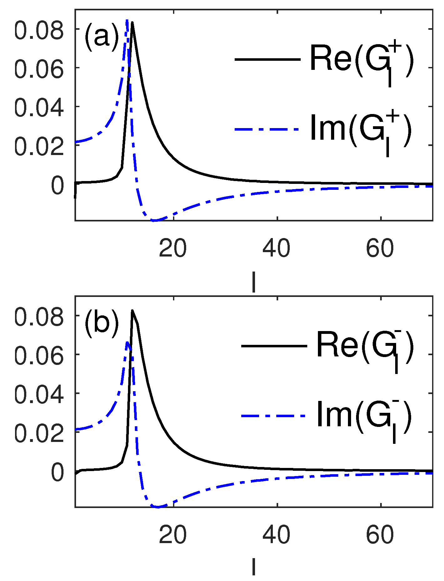
We have numerically computed G l ± as well. A typical result is displayed in Figure 2, where it is seen that G l ± features a peak around l L ω ¯ / v F and tends to zero for l beyond. These features are reminiscent of Ω ( K l ± , ω ) .

3. Application to Plasma Waves

In this section, we examine the properties of VPWs and SPWs using the above derived kinetic theory. We first look at VPWs. These are represented by the resonances determined by ϵ b ± ( k , ω ) = | ω ¯ 2 H ± | 0 . Their frequencies and decay rates are obtained from the eigenvalues of H ± . Since H ± is mostly diagonal with diagonal elements Ω 2 , the resonances are then located where Ω 2 ( K l ± , ω ) ω ¯ 2 . In Figure 3, we map out log | Det 1 ω ¯ 2 H ± | l log | 1 ω ¯ 2 Ω 2 ( K l ± , ω ) | in the ω -k plane at various values of the Fuchs parameter p. Since this is a sum of the contributions from all resonances with the same k , it is not possible to discern individual resonances unless L is extremely small so that the resonances are well separated. The VPW resonances are largely concentrated around ω = 0 and ω = ω p , since Ω ( K l ± , ω ) sits around ω p for small l but goes to zero for large l.
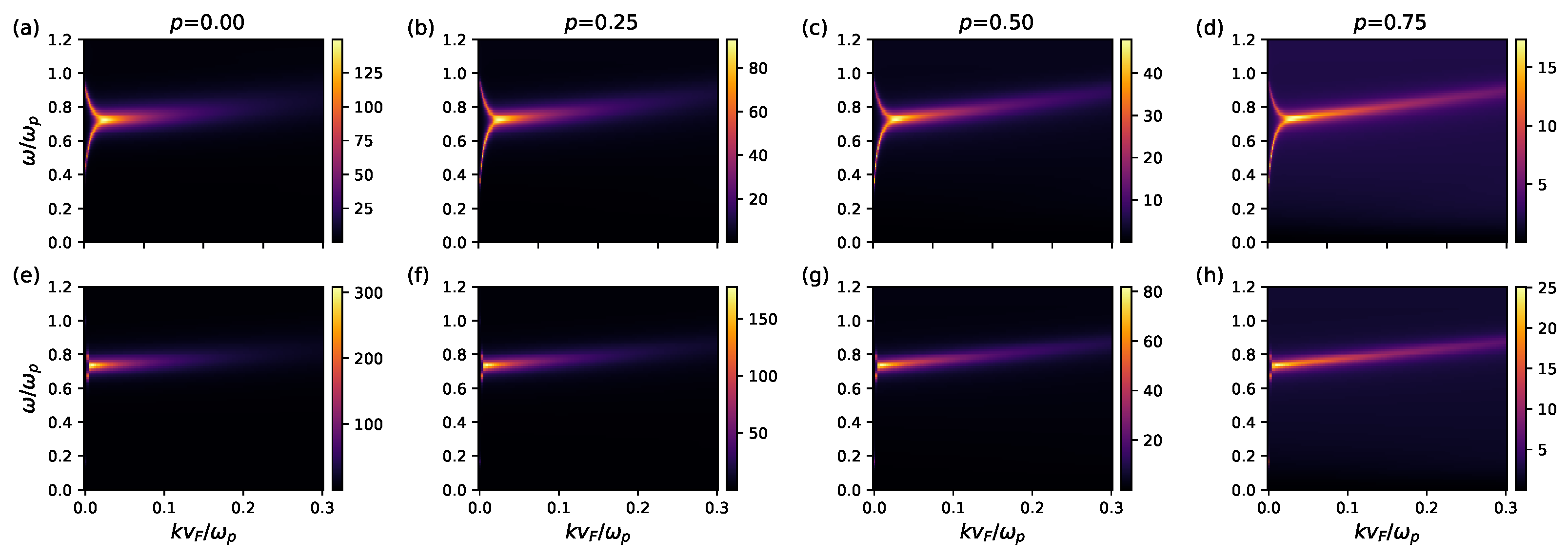
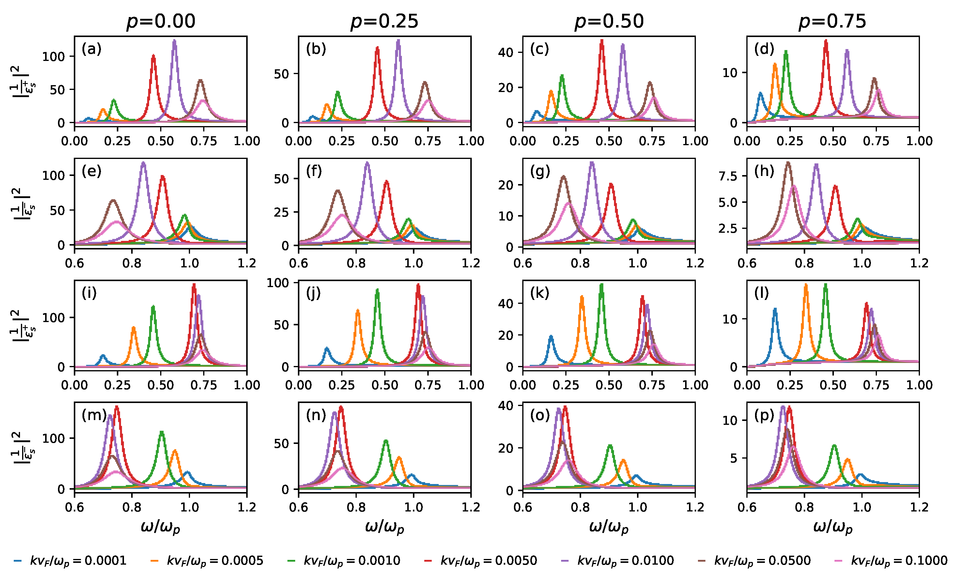
As for SPWs, their dispersion and decay rates are determined by ϵ s ± ( k , ω ) = 0 . To visualize them, we numerically compute the quantity | 1 ϵ + ( k , ω ) | 2 + | 1 ϵ ( k , ω ) | 2 and map it out in the ω -k plane, which features a peak at each SPW resonance for given k. The peak position gives the SPW frequency ω ± ( k ) , while its half width at full maximum gives the decay rate ν ± ( k ) . The maps are displayed in Figure 4 at various values of p, and example peaks are shown in Figure 5. The SPW resonances disperse along the bright lines in the map. It is seen that the symmetric SPWs and the anti-symmetric ones are nearly degenerate, i.e., ω + ( k ) ω ( k ) for large k L 1 , whereby the surfaces of the film are decoupled. As k decreases toward zero while still larger than 1 / L , both ω + ( k ) and ω ( k ) tend to the universal value ω p / 2 regardless of the value of p. Indeed, ω ± ( k ) exhibits virtually no dependence on p. For k L > 1 , ω ± ( k ) increase linearly with increasing k. As well known, this stands in contrast with the LDM, by which the frequency would approach the universal constant.
While little affecting the SPW dispersion, surface roughness—as reflected in the value of p—does significantly affect the spectral weight of the SPW resonances. The spectral weight for a Lorentzian peak is given by its height. As seen in Figure 5, the peak height quickly diminishes as p increases, and vanishes at p = 1 . We found that the height roughly goes as h 0 ( 1 p ) , where h 0 depends on k.
We have extracted the full width at full maximum (FWFM) of the SPW resonance peaks using Lorenzian fitting. It is emphasized that the peaks are nicely fitted by Lorentzians for all values of k but the smallest, for which the as-obtained FWFM—which equals 2 ν ± —should be taken with a grain of salt. The results are displayed in Figure 6 for a thin film ( L = 100 v F / ω p ) alongside a thick one ( L = 500 v F / ω p ). One may note that, for a not-so-small k, the FWFM increases linearly with k and the resulting ν ± can be well fitted by ν ± ( k ) a k + b . Here, both the coefficient a > 0 and the residual b vary with p. In Figure 6, one may see that a decreases with p, yet b increases with p. However, b seems to be bounded by 1 / τ from below, i.e., ν ± ( k ) τ 1 . Such a linear increase is a characteristic of Landau damping [77,78]. As k decreases toward zero, ν ± ( k ) starts to deviate from the linear dependence and rises up to a high value, which may be due to the strong coupling between the surfaces. For thicker films, such coupling occurs for smaller k and, hence, the linear dependence persists to a lower value of k, as can be seen by comparing the upper two rows of panels to the lower two in Figure 6.
In previous works [67,71,73,79,80], one of us studied SPWs for a semi-infinite metal with a similar method. It was shown there that surface roughness could alter the SPW frequency, in disagreement with the present finding. This discrepancy occurs because in those works the term H ± in Equation (48) was neglected. The present work shows that H ± is essential to obtain the correct SPW frequency, even though its elements are small. Moreover, H ± represents surface scattering effects and contributes to the decay of SPWs. Without this term, which is indeed negligible for VPWs, the decay rate ν ± could go below 1 / τ for a small k, as shown in those works.

4. Summary

In summary, we have provided a generic formalism for evaluating the charge density–density response function for a metal film with the conductivity tensor as the only input. We then applied the semi-classical model to calculate the conductivity, thereby establishing a kinetic theory for the response function. The main advantage of the kinetic theory is that it enables a simple way to study the effects of surface roughness through the Fuchs parameter p.
As an application, we employed the theory to analyse the properties of SPWs and VPWs. We found that the SPW dispersion does not depend much on p, whereas the decay rate of SPWs increases mildly as p increases. The most significant effect of surface roughness is seen in the spectral weight of the SPW resonances, which is drastically reduced as p increases. For specularly reflecting surfaces, the spectral weight vanishes, in accordance with the fact that SPWs are not supported in this case.

Author Contributions

Conceptualization, methodology: H.-Y.D.; investigation, formal analysis: S.P., C.L. and H.-Y.D.; validation, software, data curation, visualization: S.P., C.L. and H.B.; writing—original draft preparation: S.P., C.L. and H.-Y.D.; writing—review and editing: S.P., C.L., H.B. and H.-Y.D.; supervision, project administration: H.-Y.D. All authors have read and agreed to the published version of the manuscript.

Funding

This research received no external funding.

Data Availability Statement

All data are available upon request from the corresponding author. The computing scripts are documented at https://github.com/Spraill/semi-classical-slab-response-function, accessed on 28 August 2023.

Acknowledgments

We acknowledge the support of the Supercomputing Wales Project, through which most of the computation was conducted. The work was developed out of an undergraduate project (Sam Praill and Charlotte Lawton).

Conflicts of Interest

The authors declare no conflict of interest.

References

  1. Kulik, I.O. Thomas–Fermi screening of a moving surface charge. Low Temp. Phys. 1997, 23, 650. [Google Scholar] [CrossRef]
  2. Silkin, V.M.; Kazansky, A.K.; Chulkov, E.V.; Echenique, P.M. Time-dependent screening of a point charge at a metal surface. J. Phys. Condens. Matter 2010, 22, 304013. [Google Scholar] [CrossRef]
  3. Muino, R.D.; Sanchez-Portal, D.; Silkin, V.M.; Chulkov, E.V.; Echenique, P.M. Time-dependent electron phenomena at surfaces. Proc. Natl. Acad. Sci. USA 2011, 108, 971. [Google Scholar] [CrossRef]
  4. Mizielinski, M.S.; Bird, D.M.; Persson, M.; Holloway, S. Spectrum of electronic excitations due to the adsorption of atoms on metal surfaces. J. Chem. Phys. 2005, 122, 084710. [Google Scholar] [CrossRef] [PubMed]
  5. Tsuei, K.-D.; Plummer, E.W.; Liebsch, A.; Pehlke, E.; Kempa, K.; Bakshi, P. The normal modes at the surface of simple metals. Surf. Sci. 1991, 247, 302. [Google Scholar] [CrossRef]
  6. Ibach, H.; Mills, D.L. Electron Energy Loss Spectroscopy and Surface Vibrations; Academic Press: New York, NY, USA, 1982. [Google Scholar]
  7. Nazarov, V.U.; Silkin, V.M.; Krasovskii, E.E. Role of the kinematics of probing electrons in electron energy-loss spectroscopy of solid surfaces. Phys. Rev. B 2016, 93, 035403. [Google Scholar] [CrossRef]
  8. Landau, L.D.; Lifshitz, E.M. Electrodynamics of Continuous Media; Pergamon Press: London, UK, 1960. [Google Scholar]
  9. Despoja, V.; Echenique, P.M.; Sunjic, M. Nonlocal microscopic theory of quantum friction between parallel metallic slabs. Phys. Rev. B 2011, 83, 205424. [Google Scholar] [CrossRef]
  10. Remy, M. Theory concerning the interaction of an alkali atom and a metallic surface. J. Chem. Phys. 1970, 53, 2487. [Google Scholar] [CrossRef]
  11. Alducin, M.; Muino, R.D.; Juaristi, J.I. Non-adiabatic effects in elementary reaction processes at metal surfaces. Prog. Surf. Sci. 2017, 92, 317. [Google Scholar] [CrossRef]
  12. Moskovits, M. Surface roughness and the enhanced intensity of Raman scattering by molecules adsorbed on metals. J. Chem. Phys. 1978, 69, 4159. [Google Scholar] [CrossRef]
  13. Rother, A.I.C.J.; Gregor, I.; Janshoff, A.; Enderlein, J. Metal-induced energy transfer for live cell nanoscopy. Nat. Photonics 2014, 8, 124. [Google Scholar]
  14. Brown, D.; Deng, H.-Y. Hydrodynamic effects on the energy transfer from dipoles to metal slab. J. Chem. Phys. 2021, 155, 114109. [Google Scholar] [CrossRef]
  15. Monreal, R.C. Auger neutralization and ionization processes for charge exchange between slow noble gas atoms and solid surfaces. Prog. Surf. Sci. 2014, 89, 80. [Google Scholar] [CrossRef]
  16. Goldman, A.M. Electrostatic gating of ultrathin films. Annu. Rev. Mater. Res. 2014, 44, 45. [Google Scholar] [CrossRef]
  17. Niv, A.; Gharghi, M.; Gladden, C.; Miller, O.D.; Zhang, X. Near-field electromagnetic theory for thin solar cells. Phys. Rev. Lett. 2012, 109, 138701. [Google Scholar] [CrossRef]
  18. Li, Y.; Sun, L.; Liu, H.; Wang, Y.; Liu, Z. Preparation of single-crystal metal substrates for the growth of high-quality two-dimensional materials. Inorg. Chem. Front. 2021, 8, 182. [Google Scholar] [CrossRef]
  19. Chu, Y.T.; Warmack, R.J.; Ritchie, R.H.; Little, J.W.; Becker, R.S.; Ferrell, T.L. Contribution of the surface plasmon to energy losses by electrons in a cylindrical channel. Part. Accel. 1984, 16, 13. [Google Scholar]
  20. Bohm, D.; Pines, D. A collective description of electron interactions: III. Coulomb interactions in a degenerate electron gas. Phys. Rev. 1953, 92, 609. [Google Scholar] [CrossRef]
  21. Pines, D. A collective description of electron interactions: IV. Electron interaction in metals. Phys. Rev. 1953, 92, 625. [Google Scholar] [CrossRef]
  22. Hubbard, J. The dielectric theory of electronic interactions in solids. Proc. Phy. Soc. A 1955, 68, 976. [Google Scholar] [CrossRef]
  23. Eguiluz, A.G.; Fleszar, A.; Gaspar, J.A. On the ab initio evaluation of dynamical electronic response in metals and its comparison with experiment. Nucl. Instrum. Methods Phys. Res. Sect. Beam Interact. Mater. Atoms 1995, 96, 550. [Google Scholar] [CrossRef]
  24. Feibelman, P.J. Surface electromagnetic fields. Prog. Surf. Sci. 1982, 12, 287. [Google Scholar] [CrossRef]
  25. Apell, P.; Ljungbert, A.; Lundgvist, S. Non-local optical effects at metal surfaces. Phys. Scripta 1984, 30, 367. [Google Scholar] [CrossRef]
  26. Horing, N.J.M.; Kamen, E.; Cui, H.-L. Inverse dielectric function of a bounded solid-state plasma. Phys. Rev. B 1985, 32, 2184. [Google Scholar] [CrossRef] [PubMed]
  27. Kawaji, J. Surface Science: The First Thirty Years; Duke, C.B., Ed.; North-Holland: New York, NY, USA, 1994. [Google Scholar]
  28. Ritchie, R.H. Plasma losses by fast electrons in thin films. Phys. Rev. 1957, 106, 874. [Google Scholar] [CrossRef]
  29. Powell, C.J.; Swan, J.B. Origin of the Characteristic Electron Energy Losses in Magnesium. Phys. Rev. 1959, 116, 81. [Google Scholar] [CrossRef]
  30. Powell, C.J.; Swan, J.B. Origin of the Characteristic Electron Energy Losses in Aluminum. Phys. Rev. 1959, 115, 869. [Google Scholar] [CrossRef]
  31. Maier, S.A. Plasmonics: Fundamentals and Applications; Springer Science & Businnes Media: New York, NY, USA, 2007. [Google Scholar]
  32. Zayats, A.V.; Igor, I.S.; Maradudin, A.A. Nano-optics of surface plasmon polaritons. Phys. Rep. 2005, 408, 131. [Google Scholar] [CrossRef]
  33. Barnes, W.L.; Dereux, A.; Ebbesen, T.W. Surface plasmon subwavelength optics. Nature 2003, 424, 828. [Google Scholar] [CrossRef]
  34. Ritchie, R.H. On surface plasma oscillations in metal foils. Prog. Theoret. Phys. 1963, 29, 607. [Google Scholar] [CrossRef]
  35. Bennett, A.J. Influence of the electron charge distribution on surface-plasmon dispersion. Phys. Rev. B 1970, 1, 203. [Google Scholar] [CrossRef]
  36. Harris, J. Surface-plasmon dispersion: A comparison of microscopic and hydrodynamic theories. Phys. Rev. B 1971, 4, 1022. [Google Scholar] [CrossRef]
  37. Barton, G. Some surface effects in the hydrodynamic model of metals. Rep. Prog. Phys. 1979, 42, 65. [Google Scholar] [CrossRef]
  38. Nakamura, Y.O. Quantization of non-radiative surface plasma oscillations. Prog. Theoret. Phys. 1983, 70, 908. [Google Scholar] [CrossRef]
  39. Gradov, O.M.; Stenflo, L. Linear theory of a cold bounded plasma. Phys. Rep. 1983, 94, 111. [Google Scholar] [CrossRef]
  40. Cirací, C.; Pendry, J.B.; Smith, D.R. Hydrodynamic Model for Plasmonics: A Macroscopic Approach to a Microscopic Problem. ChemPhysChem 2013, 14, 1109. [Google Scholar]
  41. Luo, Y.; Zhao, R.; Pendry, J.B. Van der Waals interactions at the nanoscale: The effects of nonlocality. Proc. Natl. Acad. Sci. USA 2014, 111, 18422. [Google Scholar] [CrossRef]
  42. Luo, Y.; Fernandez-Dominguez, A.I.; Wiener, A.; Maier, S.A.; Pendry, J.B. Surface plasmons and nonlocality: A simple model. Phys. Rev. Lett. 2013, 111, 093901. [Google Scholar] [CrossRef] [PubMed]
  43. Kupresak, M.; Zheng, X.; Vandenbosch, G.A.E.; Moshschalkov, V.V. Comparison of hydrodynamic models for the electromagnetic nonlocal response of nanoparticles. Adv. Theory Simul. 2018, 2018, 1800076. [Google Scholar] [CrossRef]
  44. Pitarke, J.M.; Silkin, V.M.; Chulkov, E.V.; Echenique, P.M. Theory of surface plasmons and surface-plasmon polaritons. Rep. Prog. Phys. 2007, 70, 1. [Google Scholar] [CrossRef]
  45. Newns, D.M. Dielectric response of a semi-infinite degenerate electron gas. Phys. Rev. B 1970, 1, 3304. [Google Scholar] [CrossRef]
  46. Beck, D.E. Quantum-mechanical random-phase-approximation calculation of the surface-plasmon dispersion relation for a semi-infinite electron gas. Phys. Rev. B 1971, 4, 1555. [Google Scholar] [CrossRef]
  47. Kempa, K.; Schaich, W.L. Surface-plasmon dispersion in the infinite-barrier model. Phys. Rev. B 1985, 32, 8375. [Google Scholar] [CrossRef]
  48. Toscano, G.; Straubel, J.; Kwiatkowski, A.; Rockstuhl, C.; Evers, F.; Xu, H.; Mortensen, N.A.; Wubs, M. Resonance shifts and spill-out effects in self-consistent hydrodynamic nanoplasmonics. Nat. Commun. 2015, 6, 7132. [Google Scholar] [CrossRef] [PubMed]
  49. Yan, W. Hydrodynamic theory for quantum plasmonics: Linear-response dynamics of the inhomogeneous electron gas. Phys. Rev. B 2015, 91, 115416. [Google Scholar] [CrossRef]
  50. Cirací, C.; Della Sala, F. Quantum hydrodynamic theory for plasmonics: Impact of the electron density tail. Phys. Rev. B 2016, 93, 205405. [Google Scholar] [CrossRef]
  51. Christensen, T.; Yan, W.; Jauho, A.-P.; Solijacic, M.; Mortensen, N.A. Quantum corrections in nanoplasmonics: Shape, scale, and material. Phys. Rev. Lett. 2017, 118, 157402. [Google Scholar] [CrossRef] [PubMed]
  52. Liebsch, A. Surface plasmon dispersion of Ag. Phys. Rev. Lett. 1993, 71, 145. [Google Scholar] [CrossRef] [PubMed]
  53. Garcia-Lekue, A.; Pitarke, J.M. Energy loss of charged particles interacting with simple metal surfaces. Phys. Rev. B 2001, 64, 035423. [Google Scholar] [CrossRef]
  54. Alducin, M.; Silkin, V.M.; Juaristi, J.I.; Chulkov, E.V. Energy loss of ions at metal surfaces: Band-structure effects. Phys. Rev. A 2003, 67, 032903. [Google Scholar] [CrossRef]
  55. Vergniory, M.G.; Silkin, V.M.; Gurtubay, I.G.; Pitarke, J.M. Energy loss of charged particles moving parallel to a magnesium surface: Ab initio calculations. Phys. Rev. B 2008, 78, 155428. [Google Scholar] [CrossRef]
  56. Ullrich, C.A.; Vignale, G. Theory of the linewidth of intersubband plasmons in quantum wells. Phys. Rev. Lett. 2001, 87, 037402. [Google Scholar] [CrossRef] [PubMed]
  57. Garcia-Moliner, F.; Flores, F. Introduction to the Theory of Solid Surfaces; Cambridge University Press: New York, NY, USA, 1979. [Google Scholar]
  58. Garcia-Moliner, F.; Flores, F. Classical electrodynamics of non-specular dielectric surfaces. J. Phys. 1977, 38, 851–862. [Google Scholar] [CrossRef]
  59. Flores, F.; Garcia-Moliner, F. Classical electrodynamics of non-specular conducting surfaces. J. Phys. 1977, 38, 863–870. [Google Scholar] [CrossRef]
  60. Fuchs, K. The conductivity of thin metallic films according to the electron theory of metals. Proc. Camb. Phil. Soc. 1938, 34, 100. [Google Scholar] [CrossRef]
  61. Reuter, G.E.H.; Sondheimer, E.H. The theory of the anomalous skin effect in metals. Proc. R. Soc. Lond. A 1948, 195, 338. [Google Scholar] [CrossRef]
  62. Kliewer, K.L.; Fuchs, R. Anomalous skin effect for specular electron scattering and optical experiments at non-normal angles of incidence. Phys. Rev. 1968, 172, 607. [Google Scholar] [CrossRef]
  63. Ziman, J.M. Electrons and Phonons: The Theory of Transport Phenomena in Solids; Oxford University Press: Oxford, UK, 2001. [Google Scholar]
  64. Abrikosov, A.A. Fundamentals of the Theory of Metals; Elsevier: Amsterdam, The Netherlands, 1988. [Google Scholar]
  65. Kaganov, M.I.; Lyubarskiy, G.Y.; Mitina, A.G. The theory and history of the anomalous skin effect in normal metals. Phys. Rep. 1997, 288, 291. [Google Scholar] [CrossRef]
  66. Deng, H.-Y. Electrostatic responses of anisotropic dielectric films. Euro. J. Phys. 2020, 41, 035203. [Google Scholar] [CrossRef]
  67. Deng, H.-Y. A theory of electrodynamic response for bounded metals: Surface capacitive effects. Ann. Phys. 2020, 418, 168204. [Google Scholar] [CrossRef]
  68. Deng, H.-Y. On the electrical conductivity of metals with a rough surface. Phil. Mag. 2021, 101, 729. [Google Scholar] [CrossRef]
  69. Deng, H.-Y.; Muljarov, E.A. Scattering solution to the problem of additional boundary conditions. Phys. Rev. B 2022, 106, 195301. [Google Scholar] [CrossRef]
  70. Landau, L.D.; Lifshitz, E.M. Physical Kinetics; Pergamon Press Ltd.: Oxford, UK, 1981. [Google Scholar]
  71. Deng, H.-Y. Possible instability of the Fermi sea against surface plasma oscillations. J. Phys. Condens. Matter 2017, 29, 455002. [Google Scholar] [CrossRef] [PubMed]
  72. Pekar, S.I. Dispersion of light in the exciton absorption region of crystals. Sov. Phys. 1958, 6, 785. [Google Scholar]
  73. Deng, H.-Y. A universal macroscopic theory of surface plasma waves and their losses. New J. Phys. 2019, 21, 043055. [Google Scholar] [CrossRef]
  74. Bishop, M.F.; Maradudin, A.A. Energy flow in a semi-infinite spatially dispersive absorbing dielectric. Phys. Rev. B 1976, 14, 3384. [Google Scholar] [CrossRef]
  75. Lucas, M.S.P. Electrical conductivity of thin metallic films with unlike surfaces. J. Appl. Phys. 1965, 36, 1632. [Google Scholar] [CrossRef]
  76. Utkin, A.I.; Yushkanov, A.A. Electric current distribution in a thin metal layer for various specular reflection coefficients of its surfaces. Tech. Phys. 2016, 61, 1457. [Google Scholar] [CrossRef]
  77. Landau, L.D. On the vibrations of the electronic plasma. J. Phys. 1946, 10, 25. [Google Scholar]
  78. Dawson, J. On landau damping. Phys. Fluids 1961, 4, 869. [Google Scholar] [CrossRef]
  79. Deng, H.-Y.; Wakabayashi, K.; Lam, C.-H. Universal self-amplification channel for surface plasma waves. Phys. Rev. B 2017, 95, 045428. [Google Scholar] [CrossRef]
  80. Deng, H.-Y. Theory of nonretarded ballistic surface plasma waves in metal films. Phys. Rev. B 2017, 95, 125442. [Google Scholar] [CrossRef]
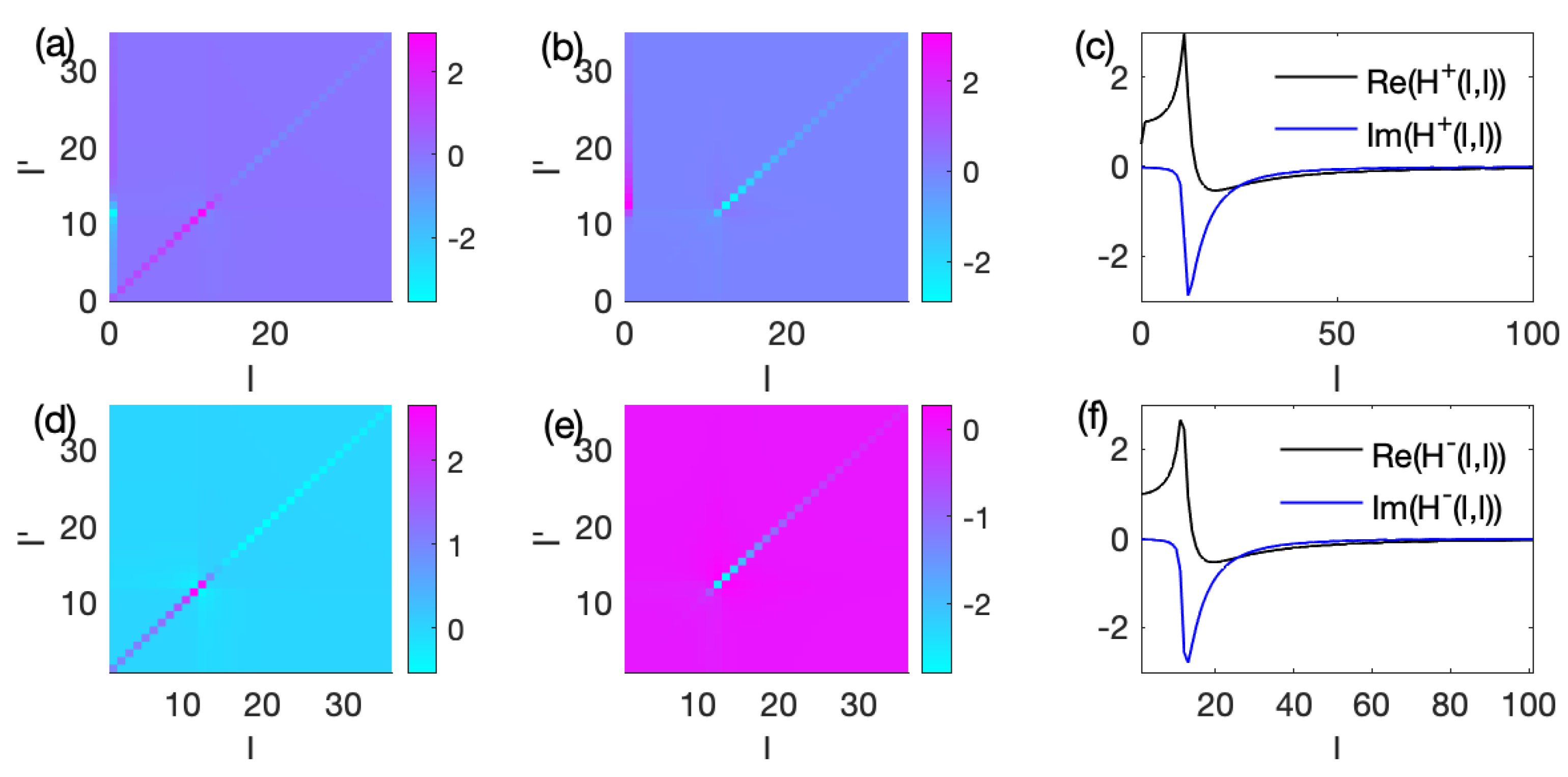
Figure 1. Numerically computed H l , l + (ac) and H l , l (df), both normalized by ω p 2 . (a,d): real parts; (b,e): imaginary parts; (c,f): diagonal elements. Parameters: ω / ω p = 0.7 , L ω p / v F = 100 , τ ω p = 50 , k v F / ω p = 0.0001 and p = 0 .
Solids 04 00017 g001
Figure 2. Numerically computed G l + (a) and G l (b). Parameters are the same as for Figure 1.
Solids 04 00017 g002
Figure 3. Maps of log Det 1 ω ¯ 2 I H ± for L ω p / v F = 100 (ad) and L ω p / v F = 500 (eh). τ ω p = 50 .
Solids 04 00017 g003
Figure 4. Maps of the quantity | 1 ϵ + ( k , ω ) | 2 + | 1 ϵ ( k , ω ) | 2 showing the dispersion of SPWs hosted on a metal film of width L and surface roughness p. (ad) are for L ω p / v F = 100 and (eh) are for L ω p / v F = 500 . τ ω p = 50 .
Solids 04 00017 g004
Figure 5. SPW peaks for various combinations of k and p. (ah): L ω p / v F = 100 ; (ip): L ω p / v F = 500 . (ad,il): symmetric modes; (eh,mp): anti-symmetric modes. τ ω p = 50 .
Solids 04 00017 g005
Figure 6. FWHM of SPW resonance peaks at various values of p. (ae,ko): symmetric SPWs; (fj,pt): anti-symmetric SPWs. τ ω p = 50 .
Solids 04 00017 g006
Disclaimer/Publisher’s Note: The statements, opinions and data contained in all publications are solely those of the individual author(s) and contributor(s) and not of MDPI and/or the editor(s). MDPI and/or the editor(s) disclaim responsibility for any injury to people or property resulting from any ideas, methods, instructions or products referred to in the content.