Abstract
The aim of the present study is to apply an embedded resistance wire technique for curing of thermosetting resins as well as for the self-healing of thermoplastic polymers. The work consists of two parts. In the first part, Kanthal resistance wires embedded in a resin plate acted as heating elements when direct electrical current was flowing through them (Joule heating). During heating, the temperature was continuously monitored using a thermal camera, and accurate temperature times for fixed position diagrams as well as temperature positions for fixed time diagrams were calculated. The effects of curing with this method were evaluated by studying the three-point bending mechanical behavior of the cured resin, comparing it with the corresponding behavior of the same resin when cured using a conventional oven curing method at the same temperature. In the second part of the present work, the possibility of using the same technique for healing existing notches and flaws in a PET thermoplastic is explored. We examined whether providing energy through the resistance wires created the right amount of heat to heal the thermoplastic, or, more specifically, whether it closed the notches and eliminated the abrasions that were artificially created on the specimens. The technique using embedded resistance wires worked equally well, with interesting and promising preliminary results regarding the curing of thermoset resins and the healing of thermoplastics.
1. Introduction
Epoxy resins are thermoset synthetic polymers. During curing, depending on their formulation, epoxy resins react with a chemically active compound such as a catalyst or a curing agent, leading to the formation of a crosslinked network [1]. Crosslinks introduce constraints for molecular movements, thus changing an epoxy’s nature from that of a viscous liquid into a tough and hard solid material with high strength, stiffness, and adhesion [2]. Curing may be performed either at room temperature or at a higher temperature by applying external heat or other external sources of energy such as ultraviolet or electron beam radiation [3].
The most important advantages of epoxy resins are their very good chemical resistance, easy processing, good adhesion, high mechanical strength, excellent viscosity, and low shrinkage. Their basic properties can be modified according to the requirements of a specific application (mixing with an additive of choice, use of modifiers, etc.), which results in a variety of applications for them. The significant advantages of epoxy resins have resulted in their rapid growth rate and widespread use. Thus, one of their most common applications is their use as matrices for the manufacture of composite materials [4], while another important application is their use as adhesives [5]. Polymeric matrix composite materials now dominate several sectors of human activity from structural applications to bio-medical uses.
The most important factor for achieving the above characteristics of epoxy resins is the curing process mentioned above, which, in turn, depends, amongst other properties, on the type of hardener, the accelerator, the weight of the resin-to hardener-ratio, and the curing temperature profile applied. In addition to these, cost is the driving force for selecting a specific curing method [6].
There are several curing heating methods used to accelerate the epoxy curing process, each one of them having its own advantages and disadvantages because they introduce different polymerization reaction rates and different reaction paths, resulting in different polymer network structures, while the final product, depending on the curing method used, has different physical properties (such as density), mechanical properties (such as strength and modulus), and thermal properties (such as the thermal expansion coefficient and the glass transition temperature) compared to those of conventional thermally processed samples [7,8,9,10,11,12,13]. For instance, the curing chambers used in conventional thermal processing can increase the rate of curing for epoxy resins; however, they are expensive and they may take up too much space in a factory while also requiring large amounts of manpower and time [14].
UV curing applications, extensively used in the electronics, coatings, and automotive industries, show advantages such as high reaction rates, good adhesion, curing at ambient temperatures, and low energy consumption [15,16,17,18]. However, this method is problematic because it doesn’t provide evenly distributed or controlled heat, leading to overheating some sections of the epoxy and thus creating unwanted local flaws in the polymeric products.
Another promising curing technique is resin transfer molding (RTM). Although RTM is a quite tolerant process, high tooling costs and difficult tool-cleaning operations and especially, extremely high non-recurring costs for part modifications are some of the greatest disadvantages of this concept [19].
To summarize, there are many different options available for epoxy resin curing including ovens as well as UV and/or electron beam radiation [20,21,22,23], RTM, and autoclaves. The common characteristic of all of the curing methods mentioned above is heat, generated during the exothermic polymerization reaction and/or applied by an external energy source. Heat is of crucial importance because it affects the epoxy’s viscosity while, at the same time, it accelerates the reaction times. In addition, the heat generated during the exothermic polymerization reaction greatly depends on the epoxy layer’s thickness. The thicker the epoxy layer, the more the heat retained by the epoxy and the faster the polymerization reaction. On the contrary, the thinner the epoxy layer, the lesser the effects of the generated heat and the slower the curing reaction. Thus, heat control during epoxy polymerization is of cardinal importance [24].
During the polymerization process, depending on the specific curing procedure applied, there are continuous changes in the mechanical and physical properties of the epoxy resin. More precisely, stiffness and strength, as well as the glass transition temperature, all increase. The properties of uncured as well as of incompletely cured polymers change continuously with time at a rate that depends on the actual storage conditions. A stable situation can only be reached after the completion of the curing process [25].
Another important common characteristic of all of these curing methods is that heat is supplied to the resin by means of an external energy source. In the present investigation, we investigated the use of an internal energy source constituted of resistant wires embedded into epoxy resins and compared it with epoxy resins cured using conventional, oven-heated thermal processing. A similar technique has been applied by other researchers wherein the curing of carbon fiber-reinforced polymer composite plates was achieved through the direct application of an electric current flowing through the carbon fibers [26,27,28,29]. This technique has been reported in the literature using different keywords and expression forms, but it is most commonly called Joule heating [26,29,30], followed by resistance or resistive heating [28,31,32,33]. Expressions such as embedded heating [34] and self-resistance electric (SRE) heating/curing [35] have also been used.
Furthermore, thermoplastics are polymers that become pliable or moldable above a specific temperature and return to a solid state upon cooling. Most thermoplastics have a high molecular weight. Polymer chains associate through intermolecular forces, which permit thermoplastics to be remolded because intermolecular interactions increase upon cooling and restore the bulk properties. In this way, thermoplastics differ from thermosetting polymers, which form irreversible chemical bonds during the curing process. Above its glass transition temperature Tg and below its melting point Tm, the physical properties of a thermoplastic change drastically without an associated phase change. Within this temperature range, most thermoplastics are rubbery due to alternating rigid crystalline and elastic amorphous regions approximating random coils [36].
In recent years, beginning in the early 1990s, scientists and engineers began creating synthetic mimics of living biological systems, having taken their cues from nature. Self- healing polymers emulate biological systems to varying extents, with some being completely autonomic and some non-autonomic systems requiring external stimuli to undergo a healing event [37]. Four fundamentally different categories of self-healing techniques exist: (1) healing by crack-filling adhesion; (2) healing by diffusion; (3) healing by bond reformation; and (4) strengthening of virgin properties in response to stress [38]. There are three different crack-filling healing mechanisms: (a) microencapsulated healing agents [39,40]; (b) phase-separated healing agents [41,42,43]; (c) healing agents in hollow fibers [44,45,46]; and (d) microvascular networks [47,48]. The healing conducted through diffusion can be performed by (a) thermoset/thermoplastic blends [49,50]; (b) dangling chain diffusion [51,52]; and (c) viscoelastic healing [53]. Healing through bond reformation can be performed only in (a) thermally reversible materials; (b) UV-initiated materials; (c) supramolecular assembly materials; and (d) materials with metal–ligand bonds [38]. Finally, regarding the mechanism of virgin property strengthening, we have to mention that these polymers incorporate mechanophores (mechanochemically active units) along their backbone that are designed to remain dormant when unperturbed but impart additional polymerization and/or chemical crosslinking to localized portions of the bulk polymer that are under stress [54].
The Joule effect can be used in self-healing materials as an internal or external source of heating and possesses attractive characteristics for developing self-healing smart materials because the electrical stimulus that acts as a trigger for self-healing effects is a simple, efficient, and economical way to repair materials in service, thus avoiding material replacement, maintenance, and early disposal [55]. The use of resistance wires embedded into polymer structures represents a promising novel technology for both curing of thermoset resins and in the case of thermoplastics, repairing microcracking and recovering the mechanical performance of the material, which otherwise would be difficult, hazardous, and costly. The method can be applied in several different industrial areas such as in structural, electronic, medical, and aerospace products.
The present work investigates an innovative type of polymerization for thermosets as opposed to the traditional method in an oven. For this purpose, a number of wires were embedded into a resin while direct current was provided to the system for different time periods (12 to 24 h). A thermo-camera was used to monitor the heat transfer from the wires to the resin while polymerization took place. Three-point bending experiments were performed to determine flexural modulus and strength values for a variety of cured specimens. The specimens we used incorporated either 1 wire or 2 wires along the length of the specimens as well as 6 and 12 wires transverse to the specimens’ length.
In the case of thermoplastics, most approaches to self-healing materials require inputs of external energy, healing agents, solvents, and/or plasticizers. In this investigation, the self-healing mechanism used bond reformation of thermally reversible materials because thermoplastics such as PET support that means of healing. In the present work, PET specimens with artificial damage were manufactured, and their ability to heal after internal heat was applied was investigated.
2. Materials and Methods
2.1. Materials
In the current investigation, RenLam CY219 (bisphenol A), combined with a curing agent, HY 5161 (diamine), at a ratio of 2:1 by weight, was utilized. The epoxy resin was supplied by Huntsman Advanced Materials, Switzerland. Density of the cured polymer was 1.1 g cm−3, and the curing time chosen was 24 h at either 50 °C or 70 °C. Viscosity of the cured system was 1–1.2 Pas at 25 °C. The properties of the resin/hardener system as given by the manufacturer, are given in Table 1.

Table 1.
Properties of the resin/hardener system as given by the manufacturer.
In the second part of this study, the thermoplastic used for the self-healing experiments was amorphous PET (polyethylene terephthalate) sheets, 0.62 mm in thickness, supplied by NGP PLASTIC, Korinthos, Greece.
Finally, as heating elements, resistance wires encoded as Kanthal®D were used. Kanthal®D is the trademark for a family of ferritic iron–chromium (20.5–23.5%)–aluminum (4.8%) alloys (FeCrAl alloys) that are used in a wide range of applications at temperatures up to 1300 °C. The Kanthal wire’s diameter was 0.5 mm with an electrical resistivity of 1.35∙10−6 Ωm.
2.2. Specimen Manufacturing
The molds used for the specimens’ manufacturing were composed of two glass plates (125 × 105 mm) as well as four PMMA (polymethyl methacrylate) blocks (105 × 12 mm), also known as plexiglass. To ensure equal spacing between wires, guiding bores were opened on the PMMA blocks through which we ran the Kanthal wires. Epoxy plates were manufactured and later cut into specimens of appropriate dimensions according to ASTM D790-03. The dimensions of all finished specimens were 100 × 12.8 × 2.6 mm. Initially, pure epoxy resin plates were manufactured and cured in a conventional way in an oven at 50 °C for 24 h to establish a reference point.
Apart from the conventional oven curing process, an innovative curing technique was applied. Resistance Kanthal wires were introduced into the uncured epoxy resin, and an electric current was flown through them. The electric current produced heat via the Joule effect, and the heat was used to cure the epoxy resin (Figure 1). Two sets of plates were manufactured. The first type of plates contained 6 Kanthal wires, and the second type contained 12 Kanthal wires. In each case, the specimens were cured at two different temperature levels, 50 °C and 70 °C, with a curing time of 24 h. This was achieved by properly adjusting the voltage and measuring the temperature of the heating element by means of both a thermocouple and a thermal camera. All tests were repeated; plates containing either 6 or 12 Kanthal wires per plate were cured in an oven at a temperature of 50 °C in order to compare the proposed curing method with the traditional one.
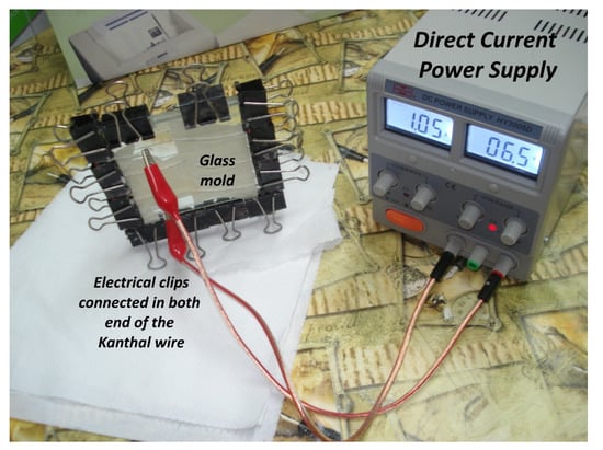
Figure 1.
Experimental setup for Joule heating curing procedure.
In addition, plates containing 12 Kanthal wires cured at temperatures of 50 °C for 12 h and 18 h via Joule heating were manufactured.
The fully cured epoxy resin plates were then cut into specimens. The plates were cut parallel and perpendicular to the Kanthal wires, resulting in specimens with 1 and 2 wires embedded in the epoxy resin in the axial direction and 6 and 12 Kanthal wires in the transverse direction, as shown in Figure 2.
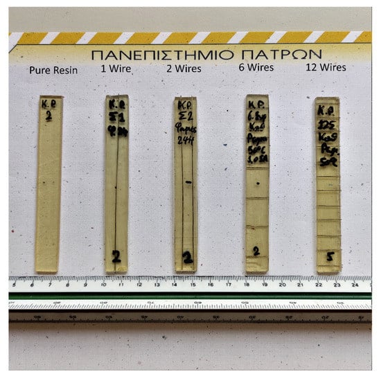
Figure 2.
Different types of specimens manufactured.
In the second part of this investigation, Kanthal wires (6 and 12 wires) were introduced into thermoplastic matrices. The Kanthal wires were placed in the middle of six layers of amorphous PET sheets, meaning that there were three layers on top of and three layers below the Kanthal wires. Next, a constant pressure of 90 kN at 85 °C for 2 h was applied to the sheets with the support of a thermo-press machine, which thermoformed the layers into homogeneous plates. Following this procedure, plates were cut parallel to the wires to dimensions of 100 × 12.8 × 2.2 mm with either one or two wires per specimen.
2.3. Quasi-Static Mechanical Tests
The manufactured thermoset specimens were subjected to a series of quasi-static three-point bending tests (ASTM D790-03) using the universal mechanical testing machine Instron 4301 (High Wycombe, United Kingdom). All tests were performed at room temperature to investigate the mechanical performance of the specimens. In all cases, a constant crosshead speed of 1 mm/min was applied. All specimens had dimensions of 100 × 12.8 × 2.6 mm and a span length of 63 mm. Six or more specimens per case (i.e., oven cured or DC-cured; 1, 2, 6, or 12 Kanthal wires) were tested to ensure the repeatability of results.
2.4. Thermal Imaging
Thermal images were captured during the Joule heating curing process using a thermal camera type of the type Flir T355 (Wilsonville, OR, USA) to simultaneously describe the temperature distribution variation with location and time.
2.5. Self-Healing Monitoring and Evaluation
The manufactured thermoplastic PET specimens were damaged, introducing an edge notch and two abrasions to each specimen, as seen in Figure 3. The aim was to investigate the self-healing capabilities of the manufactured specimens by applying a direct current through the Kanthal wires, thus producing heat via the Joule effect. In other words, the temperature was increased close to the PET glass transition temperature, Tg, (85 °C) and afterward kept constant for time periods of 1, 2, 3, 4, and 5 days. Micrographs were obtained during the heating procedure to observe the notches’ and abrasions’ width variation before and after the direct electrical current application.
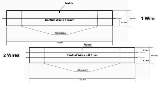
Figure 3.
Diagrams of damaged PET specimens embedded with single and double Kanthal wires.
3. Results and Discussion
In the present section, experimental findings regarding the flexural modulus and strength of thermoset specimens manufactured following different curing procedures will be presented. The results are presented in each case (modulus or strength) in charts according to the number of Kanthal heating elements incorporated into each specimen (1, 2, 6, or 12) and according to the curing method utilized. Specimens cured by Joule heating are the ones denoted with DC; the “Oven” specimens contained fibers but were cured in an oven, and the “Pure 50 °C” were cured in an oven and contained no fibers. Next, the temperature distribution during the resistance heating curing process obtained via thermal imaging is also presented. Finally, the possibility of using the same technique for the healing of existing notches and abrasions in a PET thermoplastic is explored.
3.1. Thermosets Flexural Modulus for 24-h Curing
In order to evaluate the effectiveness of the proposed curing method, the flexural moduli of the manufactured specimens are presented in Figure 4 because the modulus value can provide a reliable early indicator of an epoxy resin’s polymerization.
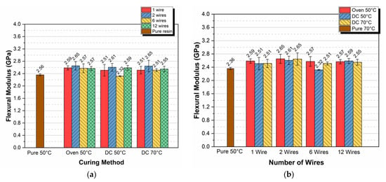
Figure 4.
Flexural modulus versus (a) curing method and (b) number of wires per specimen.
In Figure 4a, the flexural modulus versus the curing method for 1, 2, 6, and 12 Kanthal wires per specimen is given. In all types of specimens, the flexural moduli did not deviate substantially depending on the curing method; for both temperatures (50 °C and 70 °C) and for both DC and oven-cured specimens, the flexural modulus remains almost constant, averaging 2.55 GPa with a coefficient of variation on the order of 3.4%. A plot of the flexural modulus versus the number of wires per specimen is also given in Figure 4b. In this figure, it becomes even clearer that the flexural modulus almost did not deviate depending on the number of wires per specimen. From Figure 4a, we can observe that the modulus value of pure epoxy cured in an oven at 50 °C was equal to 2.36 GPa. If we compare this value with the respective maximum modulus value observed in epoxy resin specimens (2.65 GPa, 2 wires) with resistance wires embedded and cured in the same oven and at the same temperature, a difference of +14% can be observed. This difference can be attributed to the reinforcing effect of the wires and to the heat emitted back to the bulk resin by the heated wires, as long as the specimens were cured in the oven.
3.2. Thermoset Flexural Strength for 24-h Curing
In this sub-section, the mean values of the flexural strength for all types of specimens and curing procedures are presented in the bar diagrams shown in Figure 5a,b. In Figure 5a, the flexural strength versus the curing method for 1, 2, 6, and 12 Kanthal wires per specimen is given.
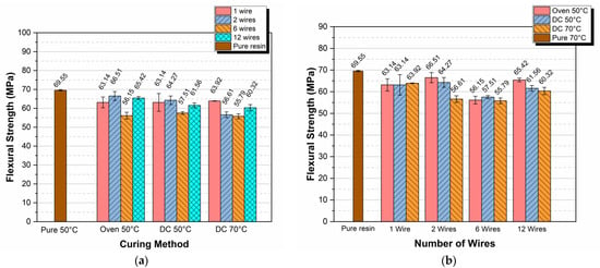
Figure 5.
Flexural strength versus (a) curing method and (b) number of wires per specimen.
Observing the variation of flexural strength with both the curing method and the number of wires embedded, it is clear that all strength values measured were lower than the respective strength value corresponding to pure resin cured in the oven at 50 °C. The maximum deviation observed was approximately 20% and corresponded to the case of 6 wires embedded into the resin and cured at 50 °C. This behavior was expected because when inserting wires into the epoxy resins, flaws were also introduced, especially in areas of wire–resin contact, mainly due to the differences in thermal expansion coefficients between the wire and the epoxy resin. The number and location of these flaws followed a stochastic type of variation that depended on too many parameters including the wire surface roughness, the heating rate, the number of wires and their location, etc., making the flexural strength a non-reliable parameter for quality evaluation as compared to the modulus [56].
3.3. Effects of Curing Time
In order to study the effects of curing time on the final flexural behavior of thermoset specimens, the values of both the flexural modulus and the strength for specimens cured by means of two embedded wires at 50 °C were compared with the respective values for pure resin specimens cured at the same temperature in an oven. Results are shown in Figure 6.
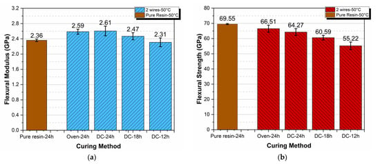
Figure 6.
Flexural modulus (a) and strength (b) dependence on curing method and time.
As observed from Figure 6a, the flexural modulus was practically independent of curing method and time. However, a deeper observation of the results reveals that the specimens designated as DC-18 h showed a small increase in their moduli relative to the pure resin–24 h specimens. This might lead to the conclusion that by using this technique, we could save curing time with parallel cost savings. However, such a conclusion is quite risky because our results are preliminary and more research is needed on the topic.
Next, on top of what was already presented and explained in the previous section related to the flexural strength variation, in Figure 6b, it can be observed that there was a decrease in flexural strength with decreases in curing time. The maximum decrease observed was on the order of 20% and corresponded to specimens designated as DC-12 h.
3.4. Temperature Distribution via Thermal Imaging
In Figure 7, four thermal images taken from a plate by means of a thermo-camera showing 2 resistant wires at 70 °C are shown. These images were taken at 0, 15, and 30 min and 24 h time instants. In these successive images, the increase in temperature throughout the plate as time passes is clearly visible. At this point, we have to mention that the number of images taken was quite big, and only representative images are presented. By comparing the four images, it can be seen that as time passed, the temperature of the plate increased, reaching a maximum value at about 30 min, while it decreased at higher times. This can be attributed to the observation that during the time period from 0 to 30 min, heat was produced not only from the wires but also from the exothermic polymerization reaction. Thus, at the time of 30 min, a small temperature over-shouting was observed (Figure 7c) on the order of 80 °C. In addition, because the duration of this reaction was on the order of 30 min, for times higher than 30 min, the reaction ceased and the temperature lowered, trending initially toward that of the wires, which was 70 °C. Subsequently, the polymer solidified, and due to its thermal insulation characteristics, the plate surface temperature was further reduced to almost 60 °C (Figure 7d).
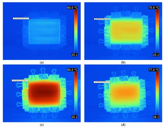
Figure 7.
Thermo-camera photos of the plate showcasing the temperature increase as time progressed (Joule heating curing at 70 °C) for (a) 0 min, (b) 15 min, (c) 30 min, and (d) 24 h.
Next, based on the thermo-camera image temperature data, graphs of temperature vs. time at different positions on the plate were plotted. In Figure 8, an X–Y system of axes is shown. On these axes, characteristic points on the plate are presented. These points are denoted as 1, 2, and 3 on the X-axis and 4, 5, 6, and 7 on the Y-axis and are used for the determination of the temperature values using the thermal images as a function of time.
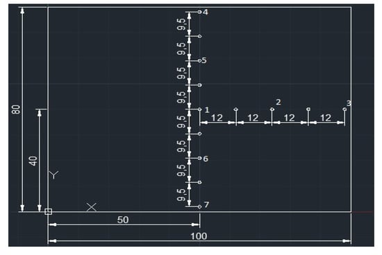
Figure 8.
X–Y system of axes and characteristic points on the plate (dimensions in mm).
For each characteristic point on the plate surface, graphs of temperature versus time for plates with 6 and 12 embedded wires at 50 °C and 70 °C, respectively, were plotted. As the number of plots is quite big, here, the plots for only two characteristic points are presented. More precisely, the temperature vs. time plots for points 1 and 4 are only shown in Figure 9. These points were selected because point 1 was located at the center of the plate, while point 4 was located at the edge. From these plots, we can observe that an initial, almost linear, increase in temperature vs. time took place, reaching a maximum at about 30 min, and this was followed by subsequent small decreases in temperature, the values of which were stabilized for times higher than 60 min. As explained above, the temperature overshooting observed at about 30 min was due to the combined heating coming from both the heated wires and the exothermic polymerization reaction which, for times higher than 30 min, ceased, so that the temperature was due to only the heat generated from the wires.
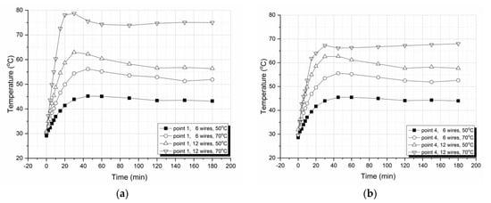
Figure 9.
Surface temperatures versus curing times for plates with 6 and 12 wires at constant curing temperatures of 50 °C and 70 °C, as validated from the thermo-camera images at (a) point 1 and (b) point 4.
Next, in order to check the symmetry and homogeneity of the temperature distribution on the plate surface, along the X and Y axes, characteristic points for different times and curing temperatures (50 °C and 70 °C) were plotted and are presented in Figure 10. These plots verify both the symmetry and homogeneity of the temperature distribution, and they are in accordance with our previously presented observations and explanations. Moreover, in all curves, a maximum temperature value is always observed at the center of the plate, while at points close to the edges, the temperature is lower due to the fact that these points were more exposed to the environment as compared with the central part of the plate.
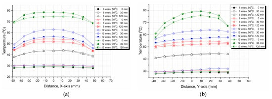
Figure 10.
Temperature variation with (a) X or (b) Y point locations on the plate surface at 50 °C and 70 °C curing temperatures and at different times.
3.5. Self-Healing of PET
To study the healing effects of Joule thermal heating, edge notches and surface abrasions on PET specimens were initially inflicted with a razor blade. Next, heating of the specimens was achieved through the resistance wires’ Joule heating effect. The width of the edge notches was continuously monitored, and photos were taken at specified time intervals. In Figure 11, Figure 12 and Figure 13, representative photos of an edge notchs’ geometry are shown, corresponding to the shape and dimensions of the notch on the PET specimen surface before and after a heating treatment at 85 °C that was performed for a number of specimens with one and two wires.
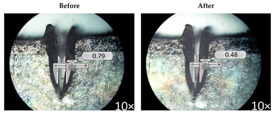
Figure 11.
Specimen 4, after 72 h of healing with 1 Kanthal wire at 85 °C.
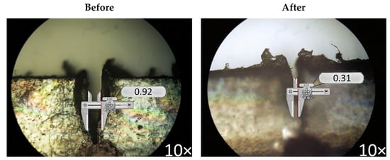
Figure 12.
Specimen 1, after 24 h of healing with 2 Kanthal wires at 85 °C.
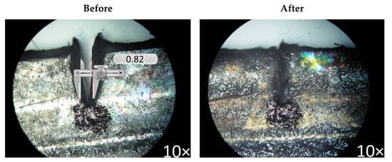
Figure 13.
Specimen 6 after 120 h of healing with 1 Kanthal wire at 85 °C.
In Figure 11, the size of the inflicted notch before and after the healing process is shown. After 72 h of healing at a temperature of 85 °C, the notch shrank from 0.79 mm to 0.48 mm, a 0.31 mm reduction, which corresponded to 39.2% of the initial inflicted notch. Thus, almost 40% healing of the notch was achieved after 72 h of heating.
However, healing of 66.3% can be seen when observing Figure 12. Figure 12 showcases a double-wired specimen after 24 h healing at 85 °C, indicating that a double-wired specimen, as compared to the single-wired one in Figure 11, can produce almost double the healing in one-third of the time. This can be attributed to the excess thermal energy provided to the specimen by the second wire and also to the wire’s closer distance to the notch, as can be seen in Figure 3.
Finally, in Figure 13, the complete healing of the inflicted notch after 120 h of healing at 85 °C for a single Kanthal-wired specimen is shown. In Table 2, the healing percentages for different healing times for both single- and double-wired specimens are given.

Table 2.
Healing percentages for single- and double-wired PET specimens.
From the numerical results shown in Table 2, it is apparent that the double-wired PET specimens healed much faster than the single-wired ones. These results are plotted as healing percentage versus heating time at 85 °C in Figure 14. From these curves, it can be seen that the initial rates of healing were 2.76 h−1 and 0.17 h−1 for the double- and single-wired specimens, respectively. This difference corresponds to a 16.2 times faster healing in the case of double-wired specimens as compared with single-wired specimens. In addition, in the double-wired specimens, complete healing was achieved at 48 h, while in the single-wired specimen, the respective time was 120 h (i.e., 2.5 times faster healing).
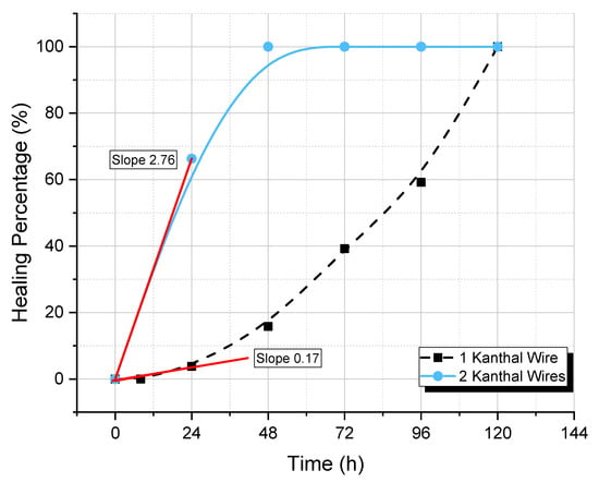
Figure 14.
Healing percentage versus heating time at 85 °C for 1- and 2-wired PET specimens.
Finally, the healing of surface abrasions on the PET specimens is shown in the photos presented in Figure 15. It is clear that after 72 h of heating with a single Kanthal wire at 85 °C, surface abrasions decreased in width and surface density, making the specimens’ surface smoother.
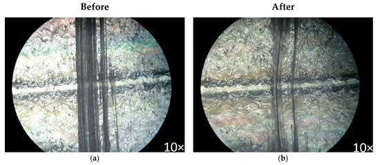
Figure 15.
Specimen 4 after 72 h of heating with 1 Kanthal wire at 85 °C; considerable healing of surface abrasions is shown.
4. Conclusions
In the present investigation, an embedded resistance wire technique was successfully applied for both epoxy resin curing and PET edge notch and abrasion healing. The main conclusions derived from the present study can be summarized as follows:
- At both temperatures (50 °C and 70 °C) and for both DC- and oven-cured epoxy specimens, the flexural modulus remained almost constant, averaging 2.55 GPa with a coefficient of variation on the order of 3.4%;
- The strength values of epoxy resins cured with the embedded resistance wire technique were lower than the respective strength values corresponding to the pure resin cured in an oven at 50 °C with a maximum deviation on the order of 20% observed in the case of 6 wires embedded into the resin and cured at 50 °C;
- Based on thermo-camera images taken on epoxy plates during curing, graphs of temperature vs. time at different positions on the plate were plotted. From these graphs, it was observed that after 30 min of curing, temperature overshooting due to both the heat generated from the wire as well as the heat liberated from the exothermic polymerization reaction was always observed, and this was followed by a progressive temperature decrease and final stabilization;
- During curing, the maximum temperature value was always observed at the center of the heated plate, while at points close to the edges, the temperature was always lower due to the fact that these points were more exposed to the environment as compared with the central part of the plate. All temperature–position diagrams along both the X and the Y-axes are symmetrical, depicting almost homogeneous and symmetric heating of the plates;
- In the case of damaged PET specimens, the initial rates of healing were 2.76 h−1 and 0.17 h−1 for the 2- and 1-wired specimens, respectively. This difference corresponds to a 16.23 times faster healing in the case of the two-wired specimens as compared with the one-wired specimen. In addition, in the two-wired specimens, due to both the wires’ positions relative to the notch and the higher amount of heat developed by the two wires, complete healing was achieved at 48 h, while in the one-wired specimen, the respective time was 120 h (i.e., 2.5 times faster healing);
- Finally, by providing heat through the resistance wires embedded into the PET specimens, artificial surface abrasions decreased in width and surface density, rendering the specimens’ surfaces smoother.
As a general conclusion, we state that the proposed technique is promising for both epoxy curing and damage healing of thermoplastics such as PET.
Author Contributions
Conceptualization, G.C.P. and L.C.K.; methodology, G.C.P.; validation, L.C.K. and A.K.; formal analysis, A.K. and S.V.; investigation, S.V., A.K.; resources, G.C.P.; data curation, G.C.P., L.C.K. and A.K.; writing—original draft preparation, L.C.K. and A.K.; writing—review and editing, G.C.P.; visualization, L.C.K. and A.K.; supervision, G.C.P.; project administration, G.C.P. All authors have read and agreed to the published version of the manuscript.
Funding
This research received no external funding.
Institutional Review Board Statement
Not applicable.
Informed Consent Statement
Not applicable.
Data Availability Statement
The data presented in this study are available in manuscript.
Conflicts of Interest
The authors declare no conflict of interest.
References
- Plazek, D.J.; Frund, Z.N. Epoxy resins (DGEBA): The curing and physical aging process. J. Polym. Sci. Part B Polym. Phys. 1990, 28, 431–448. [Google Scholar] [CrossRef]
- Pethrick, R.A. Molecular motion of polymers in concentrated solutions. Sci. Prog. 1975, 62, 599–631. [Google Scholar] [CrossRef] [PubMed] [Green Version]
- Noè, C.; Hakkarainen, M.; Sangermano, M. Cationic uv-curing of epoxidized biobased resins. Polymers 2021, 13, 89. [Google Scholar] [CrossRef] [PubMed]
- Wang, R.-M.; Zheng, S.-R.; Zheng, Y.-P. Introduction to polymer matrix composites. In Polymer Matrix Composites and Technology; Elsevier: Amsterdam, The Netherlands, 2011; pp. 1–548. [Google Scholar]
- Dinte, E.; Sylvester, B. Adhesives: Applications and Recent Advances. In Applied Adhesive Bonding in Science and Technology; Özer, H., Ed.; IntechOpen Limited: London, UK, 2018. [Google Scholar]
- Hara, O. Curing agents for epoxy resins. Three Bond Tech. News 1990, 1–10. [Google Scholar] [CrossRef]
- Carbas, R.J.C.; Marques, E.A.S.; Da Silva, L.F.M.; Lopes, A.M. Effect of cure temperature on the glass transition temperature and mechanical properties of epoxy adhesives. J. Adhes. 2014, 90, 104–119. [Google Scholar] [CrossRef]
- Abliz, D.; Duan, Y.; Steuernagel, L.; Xie, L.; Li, D.; Ziegmann, G. Curing methods for advanced polymer composites—A review. Polym. Polym. Compos. 2013, 21, 341–348. [Google Scholar] [CrossRef]
- Berejka, A.J.; Cleland, M.R.; Galloway, R.A.; Gregoire, O. X-ray curing of composite materials. Nucl. Instrum. Methods Phys. Res. Sect. B Beam Interact. Mater. At. 2005, 241, 847–849. [Google Scholar] [CrossRef]
- Horikoshi, S.; Arai, Y.; Serpone, N. In search of the driving factor for the microwave curing of epoxy adhesives and for the protection of the base substrate against thermal damage. Molecules 2021, 26, 2240. [Google Scholar] [CrossRef] [PubMed]
- Aghababaei Tafreshi, O.; Van Hoa, S.; Shadmehri, F.; Hoang, D.M.; Rosca, D. Determination of convective heat transfer coefficient for automated fiber placement (AFP) for thermoplastic composites using hot gas torch. Adv. Manuf. Polym. Compos. Sci. 2020, 6, 86–100. [Google Scholar] [CrossRef]
- Mahdi, S.; Kim, H.J.; Gama, B.A.; Yarlagadda, S.; Gillespie, J.W. A comparison of oven-cured and induction-cured adhesively bonded composite joints. J. Compos. Mater. 2003, 37, 519–542. [Google Scholar] [CrossRef]
- Bayerl, T.; Duhovic, M.; Mitschang, P.; Bhattacharyya, D. The heating of polymer composites by electromagnetic induction—A review. Compos. Part A Appl. Sci. Manuf. 2014, 57, 27–40. [Google Scholar] [CrossRef]
- The Science Behind the Epoxy Curing Process. Available online: https://www.heatxperts.com/en/blog/post/the-science-behind-the-epoxy-curing-process.html (accessed on 22 July 2021).
- Bednarek, M.; Borska, K.; Kubisa, P. Crosslinking of Polylactide by High Energy Irradiation and Photo-Curing. Molecules 2020, 25, 4919. [Google Scholar] [CrossRef]
- Salih, A.M.; Ahmad, M.B.; Ibrahim, N.A.; HjMohd Dahlan, K.Z.; Tajau, R.; Mahmood, M.H.; Yunus, W.M.Z.W. Synthesis of radiation curable palm oil-based epoxy acrylate: NMR and FTIR spectroscopic investigations. Molecules 2015, 20, 14191–14211. [Google Scholar] [CrossRef] [PubMed] [Green Version]
- Vacche, S.D.; Vitale, A.; Bongiovanni, R. Photocuring of epoxidized cardanol for biobased composites with microfibrillated cellulose. Molecules 2019, 24, 3858. [Google Scholar] [CrossRef] [PubMed] [Green Version]
- Wei, D.; Chen, L.; Xu, T.; He, W.; Wang, Y. Synthesis and characterization of a novel borazine-type UV photo-induced polymerization of ceramic precursors. Molecules 2016, 21, 801. [Google Scholar] [CrossRef] [Green Version]
- Räckers, B. Introduction to resin transfer moulding. In Resin Transfer Moulding for Aerospace Structures; Springer: Dordrecht, The Netherlands, 1998; Volume 20, pp. 1–24. [Google Scholar] [CrossRef]
- Kopal, I.; Vršková, J.; Bakošová, A.; Harničárová, M.; Labaj, I.; Ondrušová, D.; Valíček, J.; Krmela, J. Modelling the stiffness-temperature dependence of resin-rubber blends cured by high-energy electron beam radiation using global search genetic algorithm. Polymers 2020, 12, 2652. [Google Scholar] [CrossRef] [PubMed]
- Zhang, J.; Duan, Y.; Wang, B.; Zhang, X. Interfacial enhancement for carbon fibre reinforced electron beam cured polymer composite by microwave irradiation. Polymer 2020, 192, 122327. [Google Scholar] [CrossRef]
- Moon, S.W.; Morgan, R.J.; Lau, S.C. Hygrothermal Modeling of Thick Thermoset Resin during Electron-beam-cure—Part I: Methodology and Modeling Cure Kinetics. J. Compos. Mater. 2004, 38, 357–374. [Google Scholar] [CrossRef]
- Ribeiro, R.; Morgan, R.J.; Bonnaud, L.; Lu, J.; Sue, H.J.; Choi, J.; Lopata, V. Characterization of the electron beam curing of cationic polymerization of diglycidylether of bisphenol a epoxy resin. J. Compos. Mater. 2005, 39, 1433–1448. [Google Scholar] [CrossRef]
- Corcione, C.E.; Freuli, F.; Frigione, M. Cold-Curing Structural Epoxy Resins: Analysis of the Curing Reaction as a Function of Curing Time and Thickness. Materials 2014, 7, 6832–6842. [Google Scholar] [CrossRef] [Green Version]
- Papanicolaou, G.C.; Paipetis, S.A.; Theocaris, P.S. Crosslinking studies in plasticized epoxies by means of dynamic measurements. J. Appl. Polym. Sci. 1976, 20, 903–910. [Google Scholar] [CrossRef]
- Athanasopoulos, N.; Sotiriadis, G.; Kostopoulos, V. A study on the effect of Joule-heating during the liquid composite molding (LCM) process and on the curing of CFRP composite laminates. In Proceedings of the 10th International Conference on Flow Processes in Composite Materials (FPCM10), Ascona, Switzerland, 11–15 July 2010; p. 5. [Google Scholar]
- Hayes, S.A.; Lafferty, A.D.; Altinkurt, G.; Wilson, P.R.; Collinson, M.; Duchene, P. Direct electrical cure of carbon fiber composites. Adv. Manuf. Polym. Compos. Sci. 2015, 1, 112–119. [Google Scholar] [CrossRef]
- Naskar, A.K.; Edie, D.D. Consolidation of Reactive Ultem®Powder-coated Carbon Fiber Tow for Space Structure Composites by Resistive Heating. J. Compos. Mater. 2006, 40, 1871–1883. [Google Scholar] [CrossRef]
- Fukuda, H. Processing of carbon fiber reinforced plastics by means of Joule heating. Adv. Compos. Mater. 1994, 3, 153–161. [Google Scholar] [CrossRef]
- Athanasopoulos, N.; Sikoutris, D.; Panidis, T.; Kostopoulos, V. Numerical investigation and experimental verification of the Joule heating effect of polyacrylonitrile-based carbon fiber tows under high vacuum conditions. J. Compos. Mater. 2011, 46, 2153–2165. [Google Scholar] [CrossRef]
- Ashrafi, M.; Smith, B.P.; Devasia, S.; Tuttle, M.E. Embedded resistive heating in composite scarf repairs. J. Compos. Mater. 2017, 51, 2575–2583. [Google Scholar] [CrossRef]
- Smith, B.P.; Tuttle, M.; Devasia, S. Embedded resistive heating for bonding of rigid composite structures in space. In Proceedings of the AIAA SPACE Forum, Orlando, FL, USA, 12–14 September 2017; pp. 1–7. [Google Scholar]
- Xu, X.; Zhang, Y.; Jiang, J.; Wang, H.; Zhao, X.; Li, Q.; Lu, W. In-situ curing of glass fiber reinforced polymer composites via resistive heating of carbon nanotube films. Compos. Sci. Technol. 2017, 149, 20–27. [Google Scholar] [CrossRef]
- Ashrafi, M.; Devasia, S.; Tuttle, M.E. Resistive embedded heating for homogeneous curing of adhesively bonded joints. Int. J. Adhes. Adhes. 2015, 57, 34–39. [Google Scholar] [CrossRef]
- Liu, S.; Li, Y.; Shen, Y.; Lu, Y. Mechanical performance of carbon fiber/epoxy composites cured by self-resistance electric heating method. Int. J. Adv. Manuf. Technol. 2019, 103, 3479–3493. [Google Scholar] [CrossRef]
- Baeurle, S.A.; Hotta, A.; Gusev, A.A. On the glassy state of multiphase and pure polymer materials. Polymer 2006, 47, 6243–6253. [Google Scholar] [CrossRef]
- Williams, K.A.; Dreyer, D.R.; Bielawski, C.W.; Williams, K.A.; Dreyer, D.R.; Bielawski, C.W. The Underlying Chemistry of Self-Healing Materials. MRS Bull. 2012, 33, 759–765. [Google Scholar] [CrossRef]
- Mauldin, T.C.; Kessler, M.R. Self-healing polymers and composites. Int. Mater. Rev. 2010, 55, 317–346. [Google Scholar] [CrossRef]
- Song, Y.K.; Lee, T.H.; Kim, J.C.; Lee, K.C.; Lee, S.-H.; Noh, S.M.; Park, Y. Il Dual Monitoring of Cracking and Healing in Self-healing Coatings Using Microcapsules Loaded with Two Fluorescent Dyes. Molecules 2019, 24, 1679. [Google Scholar] [CrossRef] [PubMed] [Green Version]
- Tian, Y.; Zheng, M.; Li, P.; Zhang, J.; Qiao, R.; Cheng, C.; Xu, H. Preparation and characterization of self-healing microcapsules of asphalt. Constr. Build. Mater. 2020, 263, 120174. [Google Scholar] [CrossRef]
- Cho, S.H.; Andersson, H.M.; White, S.R.; Sottos, N.R.; Braun, P.V. Polydimethylsiloxane-Based Self-Healing Materials. Adv. Mater. 2006, 18, 997–1000. [Google Scholar] [CrossRef]
- Cho, S.H.; White, S.R.; Braun, P.V. Self-Healing Polymer Coatings. Adv. Mater. 2009, 21, 645–649. [Google Scholar] [CrossRef]
- Meure, S.; Wu, D.Y.; Furman, S. Polyethylene-co-methacrylic acid healing agents for mendable epoxy resins. Acta Mater. 2009, 57, 4312–4320. [Google Scholar] [CrossRef]
- Vijayan, P.P.; Al-Maadeed, M.A.S.A. TiO2 nanotubes and mesoporous silica as containers in self-healing epoxy coatings. Sci. Rep. 2016, 6, 1–9. [Google Scholar] [CrossRef] [PubMed] [Green Version]
- Vijayan, P.P.; El-Gawady, Y.M.H.; Al-Maadeed, M.A.S.A. A comparative study on long term stability of self-healing epoxy coating with different inorganic nanotubes as healing agent reservoirs. Express Polym. Lett. 2017, 11, 863–872. [Google Scholar] [CrossRef]
- Lanzara, G.; Yoon, Y.; Liu, H.; Peng, S.; Lee, W.-I. Carbon nanotube reservoirs for self-healing materials. Nanotechnology 2009, 20, 335704. [Google Scholar] [CrossRef]
- Hansen, C.J.; Wu, W.; Toohey, K.S.; Sottos, N.R.; White, S.R.; Lewis, J.A. Self-Healing Materials with Interpenetrating Microvascular Networks. Adv. Mater. 2009, 21, 4143–4147. [Google Scholar] [CrossRef]
- Mohammadi, M.A.; Eslami-Farsani, R.; Ebrahimnezhad-Khaljiri, H. Experimental investigation of the healing properties of the microvascular channels-based self-healing glass fibers/epoxy composites containing the three-part healant. Polym. Test. 2020, 91, 106862. [Google Scholar] [CrossRef]
- Luo, X.; Ou, R.; Eberly, D.E.; Singhal, A.; Viratyaporn, W.; Mather, P.T. A thermoplastic/thermoset blend exhibiting thermal mending and reversible adhesion. ACS Appl. Mater. Interfaces 2009, 1, 612–620. [Google Scholar] [CrossRef]
- Hayes, S.A.; Jones, F.R.; Marshiya, K.; Zhang, W. A self-healing thermosetting composite material. Compos. Part A Appl. Sci. Manuf. 2007, 38, 1116–1120. [Google Scholar] [CrossRef]
- Yamaguchi, M.; Ono, S.; Okamoto, K. Interdiffusion of dangling chains in weak gel and its application to self-repairing material. Mater. Sci. Eng. B 2009, 162, 189–194. [Google Scholar] [CrossRef]
- Yamaguchi, M.; Ono, S.; Terano, M. Self-repairing property of polymer network with dangling chains. Mater. Lett. 2007, 61, 1396–1399. [Google Scholar] [CrossRef]
- Jr., S.J.K.; Ward, T.C.; Oyetunji, Z. Self-Healing of Poly(Ethylene-co-Methacrylic Acid) Copolymers Following Projectile Puncture. Mech. Adv. Mater. Struct. 2007, 14, 391–397. [Google Scholar] [CrossRef]
- Son, D.H.; Kim, G.Y.; Jeong, J.-E.; Lee, S.-H.; Park, Y.I.; Kong, H.; Cheong, I.W.; Kim, J.C. Influence of Material Properties on the Damage-Reporting and Self-Healing Performance of a Mechanically Active Dynamic Network Polymer in Coating Applications. Molecules 2021, 26, 2468. [Google Scholar] [CrossRef] [PubMed]
- Orellana, J.; Moreno-villoslada, I.; Bose, R.K.; Picchioni, F.; Flores, M.E.; Araya-hermosilla, R. Self-healing polymer nanocomposite materials by joule effect. Polymers 2021, 13, 649. [Google Scholar] [CrossRef] [PubMed]
- Suleiman Khayal, O.E. Literature review on imperfection of composite laminated plates. J. Microsc. Ultrastruct. 2017, 5, 119–122. [Google Scholar] [CrossRef]
Publisher’s Note: MDPI stays neutral with regard to jurisdictional claims in published maps and institutional affiliations. |
© 2021 by the authors. Licensee MDPI, Basel, Switzerland. This article is an open access article distributed under the terms and conditions of the Creative Commons Attribution (CC BY) license (https://creativecommons.org/licenses/by/4.0/).