1. Introduction
In external beam radiation therapy, radiation applied for therapeutic purposes belongs mainly to the spectral region where we have short lengths and high wave energies like X-rays and Gamma rays [
1]. Because all cells, both normal and cancerous, are destroyed by radiation, this causes further damage in cells that are in a rapidly dividing process, which is the case of the latter. These, in turn, have less capacity for recovery from the damage suffered as a result of the radiation, which provides the ability to destroy cancer cells with small, repeated doses of radiation while minimizing the risks to adjacent healthy tissue [
2]. As the value of the absorbed dose [
3] is critical when administered, it should be measured accurately. In vivo dosimetry [
4] is a standard practice to assess patient dose during treatment. The majority of diodes used in “in vivo” dosimetry are silicon detectors. The—p type diodes are the most used, since they suffer less loss of sensitivity as a function of accumulated dose, and because they are less dependent on the dose rate, as is the case for n-type diodes. In a radiotherapy department, the possibility of “in vivo” dosimetry depends on many factors such as the choice of dosimeters to be used, the characteristics of the detectors, financial conditions, work environment, training staff, etc. [
5]. In the case of a small department, these issues are all enhanced by the lack of time and personnel to perform valuable measurements [
6].
When using semiconductor detectors, there are some important characteristics that one has to consider in vivo dosimetry [
7], in particular with silicon p-type diodes [
8,
9]:
The signal stability after irradiation (the deviation of the signal must not exceed 1% in one hour when used in conventional treatments);
The intrinsic precision (the intrinsic reproducibility refers to the consistency of the detector’s signal over at least ten consecutive irradiations delivered with the same dose. The standard deviation of the measured dose should not exceed 1% within a single treatment session);
The sensitivity (there are large differences in sensitivity from diode to diode, hence the need to characterize the relative sensitivities of diodes used in an in vivo program);
The influence of dose (the variation in response with dose—the response of the diode has been shown to be proportional to the absorbed dose to doses exceeding 10 Gy. Therefore, it is expected that there is linearity of the signal for “in vivo” measurements);
The dose rate (the factors that modify the dose rate are the use of filters—there is a decrease in the dose rate and therefore they alter the response of the diodes);
The effect of temperature (there is a slight increase in response to the temperature of the diode. The explanation for this is the level of minority charge carriers);
The directional effect (there will be a result of the structural anisotropy diodes (sensitivity variation) versus the angle between the axis of the central beam and the axis of symmetry of the diode and the capuchin build-up. The more oblique radiation is, the greater the variation. This variation may reach 5% for angles of 60°).
2. Materials and Methods
The preparation of this in vivo dosimetry program involved several steps, which include
Dose calculation of input and output, comparing them with the treatment planning system;
Dose estimate to the target volume, to confirm the proper administration of irradiation and skin dose determination.
Gamma rays with average energy 1.25 MeV from a Co60 unit and X-rays from a linear accelerator (Varian) with a maximum energy of 6 MV were used.
The diodes (5 units) utilized were silicon type–p (EDE5/EDP) with a total chip thickness 0.50 ± 0.02 mm and a diameter of 1.5 ± 0.1 mm. This type of detector has a build-up cap (Polystyrene) 2 mm and (Epoxy) 3 mm, which equates to a water equivalent depth of 5 mm. The dose decreases roughly 3% behind the detector at 5 cm depth in water, with a Co60 beam (the primary beam has been significantly attenuated). The maximum signal deviation in fields from 5 × 5 cm2 to 30 × 30 cm2 is 1%. As for the sensitivity variation with temperature, it is 0.4% ± 0.1% per degree Celsius. The working conditions are as follows:
220 V-AC, 50–60 Hz;
Temperature (18 °C to 26 °C) and humidity (30% to 70%);
Operational range from 1 m Gy to 20 Gy, with a resolution of 0.001 Gy and a warm-up time of 30 min.
Contact with metals should be avoided and the adhesive tape should not be placed on top of the hood (ensuring the protection and reliability of radiation detectors, leading to more accurate and safe treatment planning and execution), but to the side. Alcohol should be used to clean them. Each diode has a 2 m connection cable, which connects to an external electrometer. The DPD-5/DPD-6 consists of a multichannel electrometer with a channel selector.
The 5-channel display, which allows one to take measurements of the input dose (incident on the dosimeter) and the output dose (corrected radiation dose) has the facility to immediately enter a correction factor (if necessary) between 1.000 and 1.999.
The Farmer ionization chamber-Type 2581, in the shape of a 0.6 cc thimble, with the wall and electrometer made of the same material (conductive plastic) was employed to crosscheck the results. The outer electrode is made of Shonka A-150 and the inner electrode is made of plastic equivalent to tissue. The build-up cap is made of lucentine, with a density of 584 mgcm2 and a surface density of 37 mgcm2. The total thickness of the build-up was 621 mgcm2.
The electrometer associated with the chamber was the Farmer Dosemeter Type 2570/1, which had two operating scales—High and Low—with a resolution of 0.0003 Gy and 0.003 Gy, respectively. The maximum input rate was 0.25 Gys-1 or 2.5 Gys-1. The leakage current is 0.5 Gys-1 for both High and Low operating modes.
It operates under reference conditions between 10 and 40 °C and takes dose and dose rate measurements.
Slabs of acrylic [PMMA] (C5H8O2) and water phantoms were also used together with a portable thermocouple (COMARK C8500) and barometers (Compensate 1983) to register the ambient conditions.
Readings were performed where the diodes were put against an ionization chamber either in the acrylic slabs or in the water phantoms at depths of 5 and 15 cm, respectively, and irradiated with beams of Cobalt and 6 MV X-rays. Reading measurements were performed by DPD/5 electrometers and Farmer Dose meters (2570/1). The electrometers have a calibration mode that allows the signal from the detector to be displayed directly as absorbed dose.
Certain procedures were established before deploying the program: For signal stability, the diodes and electrometer were placed in a room with proper connections. After three days, their dose rate was checked. Next, the diodes were irradiated with an arbitrary amount of radiation, and we waited another three days to confirm any changes in the dose rate readings.
Several preparatory steps were completed: using a ionization chamber (IC) in a water tank, the depth at which the maximum build-up occurred (in 1 mm increments) for 5 × 5, 10 × 10, 15 × 15, 20 × 20, 30 × 30, and 40 × 40 cm2 fields was evaluated. Measurements were performed from bottom to top, allowing for long intervals between readings (2 s). Then, the process was repeated with the largest available wedge. Determination of the midpoint of the build-up depth was set and was considered as fixed.
Next, each diode was placed with its cap against a cylindrical chamber, ensuring the effective point is at the depth of dose maximum. Irradiation with 100 cGy was performed and the potentiometers were adjusted to give 100 units. The influence of the diodes on each other was checked (close proximity between diodes can result in scatter, crosstalk, or thermal/electrical interference, all of which could distort the measurement of radiation dose). Finally, the reproducibility of the diodes’ response was measured.
For linearity and field measurements, the IC in an acrylic phantom with the effective point at the build-up depth was placed. The diodes should be placed on the surface, near the central beam (where the IC should be positioned), but without shading the IC. Irradiation was performed with doses of 10, 20, 30, 50, 75, 100, 125, 150, 175, and 200 cGy (measured approximately at the IC for fields of 6 × 6, 8 × 8, 10 × 10, 15 × 15, and 20 × 20 cm2) to check if the response is linear. The surface focus distance (S.F.D) was 100 cm.
The same procedures were repeated using the largest wedge to verify whether the linearity was maintained, ensuring that both the diode and the camera were aligned according to the inclination of the wedge. The distance from the focus to the surface (DFS) was 100 cm.
For the surface focus distance variations, the previous procedure was repeated but with varying of the DFS between 80, 90, 100, and 110 cm for the 10 × 10 cm2 field and doses of 50, 100, 150, and 200 cGy to check if the linearity was maintained.
To assess the temperature dependence, an acrylic plate was heated to around 50 °C in a conventional oven. The diodes were placed on the surface in the same way as described previously (with the ionization chamber at room temperature). Irradiation with a 20 × 20 cm2 field and a DFS of 75 cm was performed. The same procedure was performed, but this time both the acrylic plate and the diodes were heated together in the oven to 40 °C. The temperature was measured using a thermocouple.
To assess angular dependence, each diode was placed at the center of the field and the ionization chamber slightly apart. A 20 × 20 cm2 field and a DFS of 75 cm were used and irradiated for 3 min. To examine how the response varies with the beam’s inclination on the diodes, we started irradiating at 0° (perpendicular to the phantom) and then incremented the angle by 10° up to 60°.
Finally, all input and output factors were calculated. The input and output dose calibration factors are valid factors under reference conditions, with the input/output signals from the diode placed on the patient’s skin, on the input/output surface, together with the build-up and the input/output dose from an ionization chamber [
10].
An important parameter for diodes that are used for both input and output dose measurements is the ratio F between the input and output dose calibration factors.
F is supposed to be greater than unity due to the positions of the ionization chambers and semiconductor detectors for the determination of input and output doses.
During clinical use, the calibration factors increase as the detector accumulates dose. However, the F ratio remains the same, as the increments given by the input and output factors are the same [
11]. A pilot planning situation was performed to assess the viability of the proposed program.
3. Results
The system was stabilized by placing the diodes and their respective electrometer in a dedicated room, properly connected and identified. It was concluded that the diodes should not be used for treatments longer than the time indicated in
Table 1.
There was linearity between the readings of the ionization chamber and the diodes as seen in
Table 2; the response of the diodes was proportional to the absorbed dose by the ionization chamber in all fields measured. The correlation coefficients were approaching unity (0.989 ± 0.126).
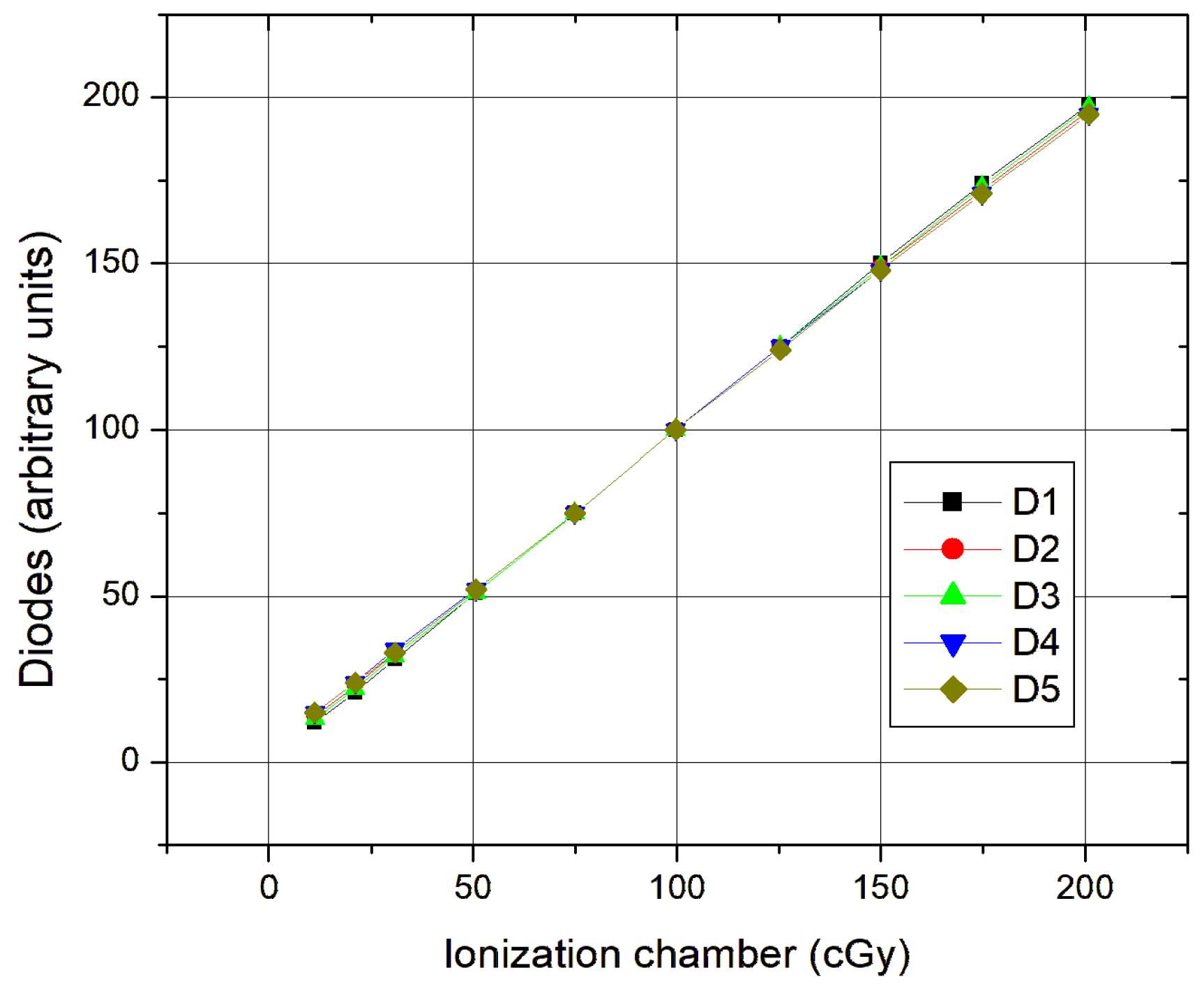
The linearity (
Figure 1) was tested with a field of 10 × 10 cm
2 and a focus distance surface FDS of 100 cm. The diodes were placed on an acrylic plate occupying an area of approximately 16 cm
2 with the ionization chamber placed at 5 cm depth at the isocenter.
In small fields (up to 10 × 10 cm2), there is a slight detachment to higher doses; this is because the diodes are already close to the edge, almost in the penumbra zone, which influences the dose.
The use of a wedge was also tested. The conditions were the same as previous. The temperature was 19.0 °C and the pressure was 1001 mbar. The diodes were placed so as not to make the shadow ionization chamber. The diodes and the chamber had the same coordination to the inclination of the wedge. Calibration curves of the diodes with the wedge were drawn out and a filter factor (0.41) was achieved for these cases when this was necessary.
To study the influence of temperature on the diodes, the acrylic plates were placed in an oven for 24 h at 50 °C occupying an area of approximately 16 cm
2. A field of 20 × 20 cm
2 and an FDS of 75 cm was used. The necessary time of placement of the diodes on top of the acrylic plate after removing the plate from the oven was roughly 3 min. Temperature and pressure were registered (22.0 °C and 1021 mbar). A reading of the diodes at the reference temperature (22 °C) was initially performed. Then, with the help of the thermocouple, recordings of the diode’s values in 25 s intervals were made, as seen in
Figure 2. The variation in the sensitivity of the diodes below 40 °C is about 0.3% per degree, which is lower than the 0.4% provided by the catalog.
As for the response stability, most diode readings cluster around 1.00 ± 0.02 for 22–36 °C, indicating stable behavior. There is an increased variability noticeable above 36 °C, especially at 38.4 °C (±0.03). As for lower temperatures, below ~30 °C, the response is slightly below 1.00 but with lower deviations, as seen in
Table 3.
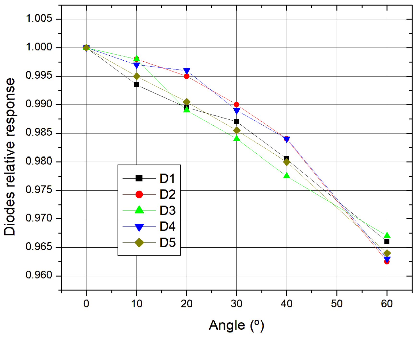
As for the directional effect, it started by placing the diodes on an acrylic plate at the center of the field, with each diode having a central effective point. We used a field 20 × 20 cm
2 (respectable homogeneity) and an FDS of 75 cm. The irradiation time was about 3 min. As seen in
Figure 3, firstly, 0° was measured and then with 10° increments up to 60 degrees in both directions. None of the diodes presented more than a 5% variation, thus, in accordance with what was expected.
As seen, the response decreases with angle, the mean diode response declines steadily from 1.00 at 0° to 0.96 at 60°. There is low variability since the standard deviations are low (≤0.003), indicating consistent performance among all diodes. There is high confidence in the results since the confidence intervals are narrow (≤±0.0034) suggesting a strong measurement reliability.
Finally, calibration factors were calculated in accordance with the dose calibration factor for input and calibration factors for doses output at different beam doses and different fields. Regarding the actual calculated dose for each diode or the input or the output, one can say from
Table 4 that the results are quite acceptable. As expected, the ratio F increases as the dose increases in each field.
The calibration factors are consistent between ~1.07–1.08. Across all field sizes, the mean calibration factor (F) is between 1.068 and 1.080. This implies the diode over-responds compared to the ion chamber by ~7–8% on average. There is a slight size dependence, since it is noticeable that there is a slight increase in F for smaller fields (e.g., 10 × 10 and 15 × 15 cm2). The 20 × 20 cm2 field shows the lowest F (1.072) and highest range, possibly due to greater variation at low doses. As for the dose dependence, F tends to increase with dose for all fields: At low doses (10 cGy), F ~1.01–1.06; and at high doses (~150 cGy), F ~1.12–1.14. This suggests a non-linear diode response requiring dose-dependent calibration. Diode measurement uncertainties (St. Dev.) ranges from 1.3 to 2.3, which is moderate but acceptable. The diodes systematically overestimate dose compared to the ion chamber, by ~7–8% depending on field size and dose. Calibration factors (F) are needed for clinical correction and should be field-size specific and dose-dependent. At low doses, there is slightly higher variability suggesting buildup or leakage corrections.
A pilot planning situation was carried out, where the absorbed dose for the diodes was calculated as follows:
Dose = Diode reading × Calibration factor (input or output) × Correction factors (FDS × Direction × Temperature and Pressure). The errors are shown in
Table 5 for the several diodes for different fields and mean dose against the dose of an IC.
With regard to the actual dose calculated for each diode, both at the input and output, we can say that it is quite acceptable, since when we compare it with the respective dose from the ionization chamber, we see that the differences are all less than 1%.
4. Discussion
An in vivo dosimetry routine is crucial for quality control in radiotherapy. The concept of Quality Control in radiotherapy encompasses various elements, ranging from patient care to the equipment used, with the fundamental principle that every detail in the process matters. Dosimetry is a key component of quality assurance, specifically physical dosimetry, which involves a series of parameters to ensure that the treatment is appropriate, meaning it guarantees the correct dose is delivered under specific conditions, minimizing damage to healthy tissues.
The system was stabilized and based on performance monitoring; it was concluded that the diodes should not be used for treatments exceeding the stability times presented in
Table 1. These limits are in line with findings from diode characterization studies [
12,
13], where p-type diodes such as Sun Nuclear QED and IBA’s ISORAD-p models demonstrated consistent short-term performance but required proper correction factors and temperature stabilization for longer exposures.
The diodes exhibited a response linearly proportional to the absorbed dose as measured by the ionization chamber across all tested fields, with correlation coefficients approaching unity (0.989 ± 0.126), in line with the expected performance for modern p-type diode systems as shown in comparative studies [
14].
In small fields (≤10 × 10 cm2), a slight deviation to higher doses was observed. This is attributable to diode placement near the penumbra zone, which impacts local dose uniformity, a well-recognized issue in diode dosimetry programs using either Sun Nuclear or IBA systems.
Wedge-filtered conditions were also evaluated under consistent environmental parameters. Diodes and the ionization chamber were aligned with the wedge orientation to avoid shadowing artifacts. The derived calibration curves indicated a wedge correction factor of 0.41, consistent with literature values [
12] and confirming the necessity of wedge-specific calibrations in diode-based in vivo programs.
To assess temperature sensitivity, diodes on acrylic plates were heated to 50 °C and allowed to cool. At temperatures below 40 °C, the sensitivity variation was ~0.3%/°C, slightly better than the 0.4%/°C typically reported for Sun Nuclear and ISORAD-p p-type systems, indicating good thermal stability.
Directional dependence was investigated using a 20 × 20 cm
2 field and angular measurements from 0° to 60° in 10° increments. None of the diodes showed variation exceeding 5%, confirming adequate angular stability, as also observed in comparative studies [
14,
15].
Calibration factors were calculated for both input and output doses across various field sizes and ionization chamber doses. As seen in
Table 2, diode responses scaled predictably with dose, and the calculated factors were consistent with those observed in the deployment of clinical in vivo dosimetry programs using p-type diodes from Sun Nuclear and PTW.
Diodes are delicate components that require protection, which is why they are encapsulated. This protective encapsulation usually provides the necessary thickness to balance the detector’s electronics. Typically, the sensitivity of a diode increases with temperature [
16] due to changes in carrier mobility and the number of traps present in the detector’s crystal. The variation in sensitivity with temperature also depends on the accumulated dose the diode has received. This effect is significant because when a diode is placed in contact with a patient, its temperature may rise by up to 10 °C above ambient temperature within 2 to 3 min, before stabilizing.
Thermoluminescent dosimetry is commonly used due to the small size of TL dosimeters and their relatively simple calibration process, whereas diodes offer the advantage of providing immediate results.
In vivo dosimetry is particularly useful for individual patient measurements and should be incorporated into at least the first treatment sessions of all quality control programs [
17].
As a comparison with other methods, we show the advantages and disadvantages in
Table 6 and
Table 7. Thermoluminescent dosimeters (TLDs) are the main competitors with semiconductor diodes for in vivo dosimetry. One can also see that diodes are worse rated than the TLDs with relation to the patients’ comfort due to the cables but have the advantage of having immediate results opposed to the TLDs with waiting periods up to 20 h.
As for the detector’s response as a function of several factors, the IC and TLDs are less impacting than the diodes.
As one can conclude, the response of the TLDs looks the finest; nonetheless, for an “in vivo” dosimetry routine with an immediate response, the diodes look relatively promising for the purpose proposed and permit immediate intervention in the event of a discrepancy.
5. Conclusions
The diodes were carefully selected, resulting in reliable outcomes. In vivo dosimetry with diodes provides the advantage of obtaining immediate data, even while the patient remains in the treatment position on the gurney.
Regarding system stability, it was concluded that diodes should not be used for treatments longer than 10–12 min. P-type silicon diode detectors are not ideal for prolonged use in radiotherapy due to signal drift, thermal effects, and charge trapping. While these issues are fundamental to the physics of the material, alternative designs (like n-type diodes), real-time correction methods, and thermal management can improve performance. By carefully adjusting the relative position of the diodes to prevent systematic errors, the reproducibility of diode responses was evaluated. The results showed that all diodes were reliable, as the deviation was less than 1%. Calibration curves were obtained using a wedge of a linear accelerator (6 MV photons), with a dose variation of only 0.13% in the diode readings.
In terms of signal variation with field size, the results showed no significant difference across different field types, as the diode responses remained consistent. A correction factor of 1 was determined to be appropriate. Similarly, the signal variation with respect to the distance from the focal surface did not affect the diode response, confirming a correction factor of 1.
Temperature variation was also measured, and the results were consistent with other studies [
18]. For typical clinical scenarios with a few minutes of irradiation, the correction factor can be considered as 1, meaning no adjustment is needed.
Regarding the directional effect, a correction factor was observed, increasing with the angle between the diode’s central axis and the central ray of the radiation beam. This variation is primarily due to the diode’s design. No diode showed a deviation greater than 5% at either the entrance or exit, which aligns with the validation requirements [
19].
Calibration factors for both input and output were calculated [
20]. These factors varied with calibration, and a quotient between them was determined.
In vivo dosimetry remains the most reliable method for verifying the accuracy of the prescribed dose delivered to patients [
21]. While direct measurements at the target site are often impractical, measuring the entrance dose at one or more fields provides an accurate way to assess the delivered dose. Diode-based entrance dose measurements have proven effective and valuable in our patient population, yielding consistent and precise readings. These results enable a comprehensive evaluation of each patient’s treatment and allow for intervention when necessary, ensuring that dose variations remain within acceptable limits. While ideally, each patient would have measurements for every treatment, this is not practical, as frequent measurements could alter the intended dose due to attenuation from the diode.


