

Enhancing Power Quality in a PV/Wind Smart Grid with Artificial Intelligence Using Inverter Control and Artificial Neural Network Techniques


Abstract
1. Introduction
2. DC-AC Microgrid Control Strategies
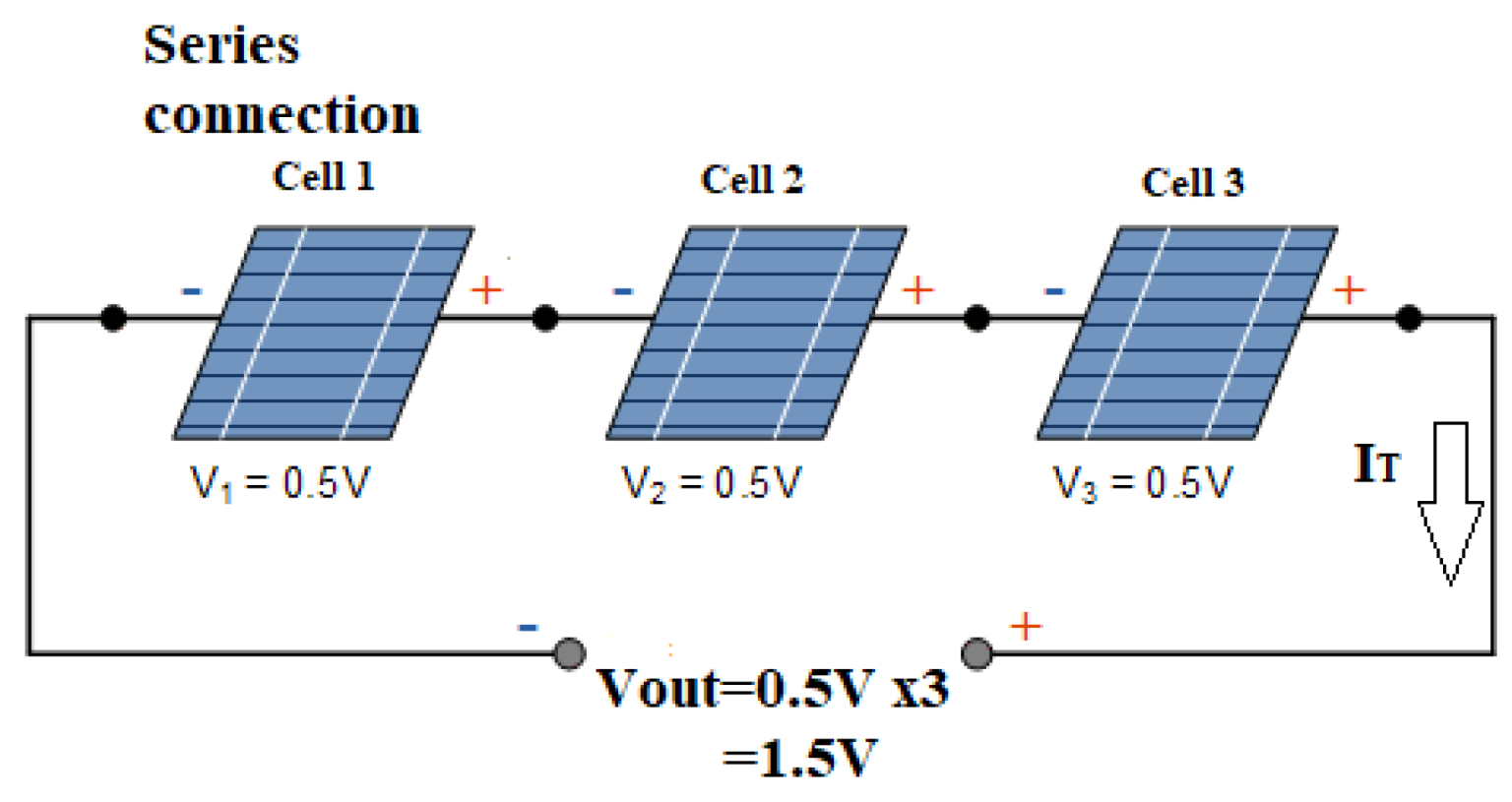
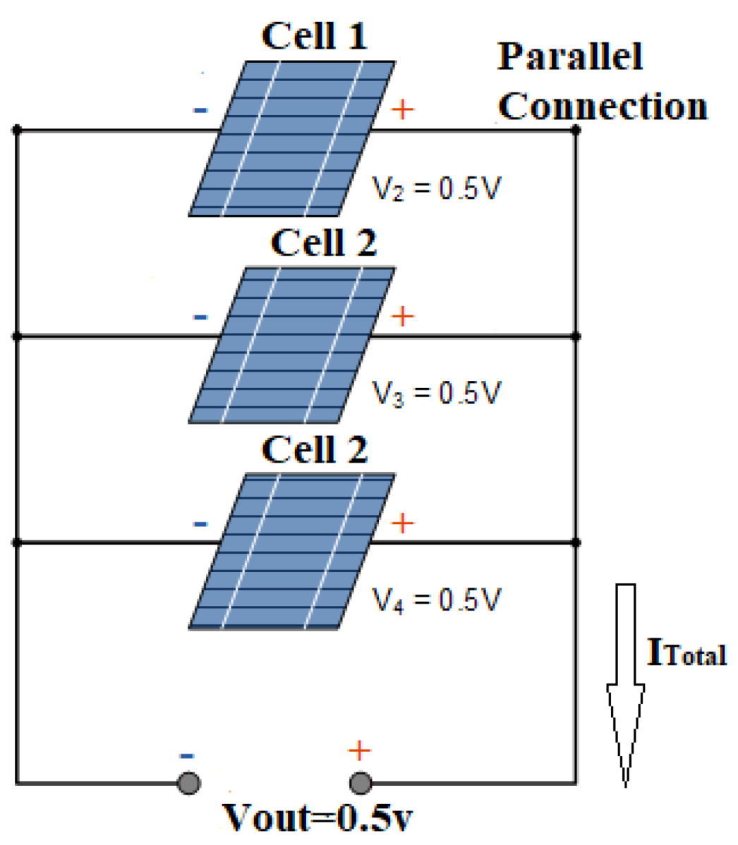
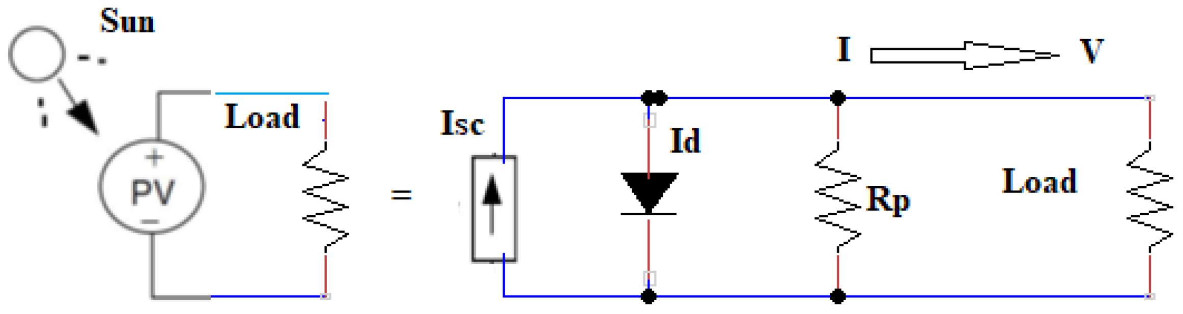
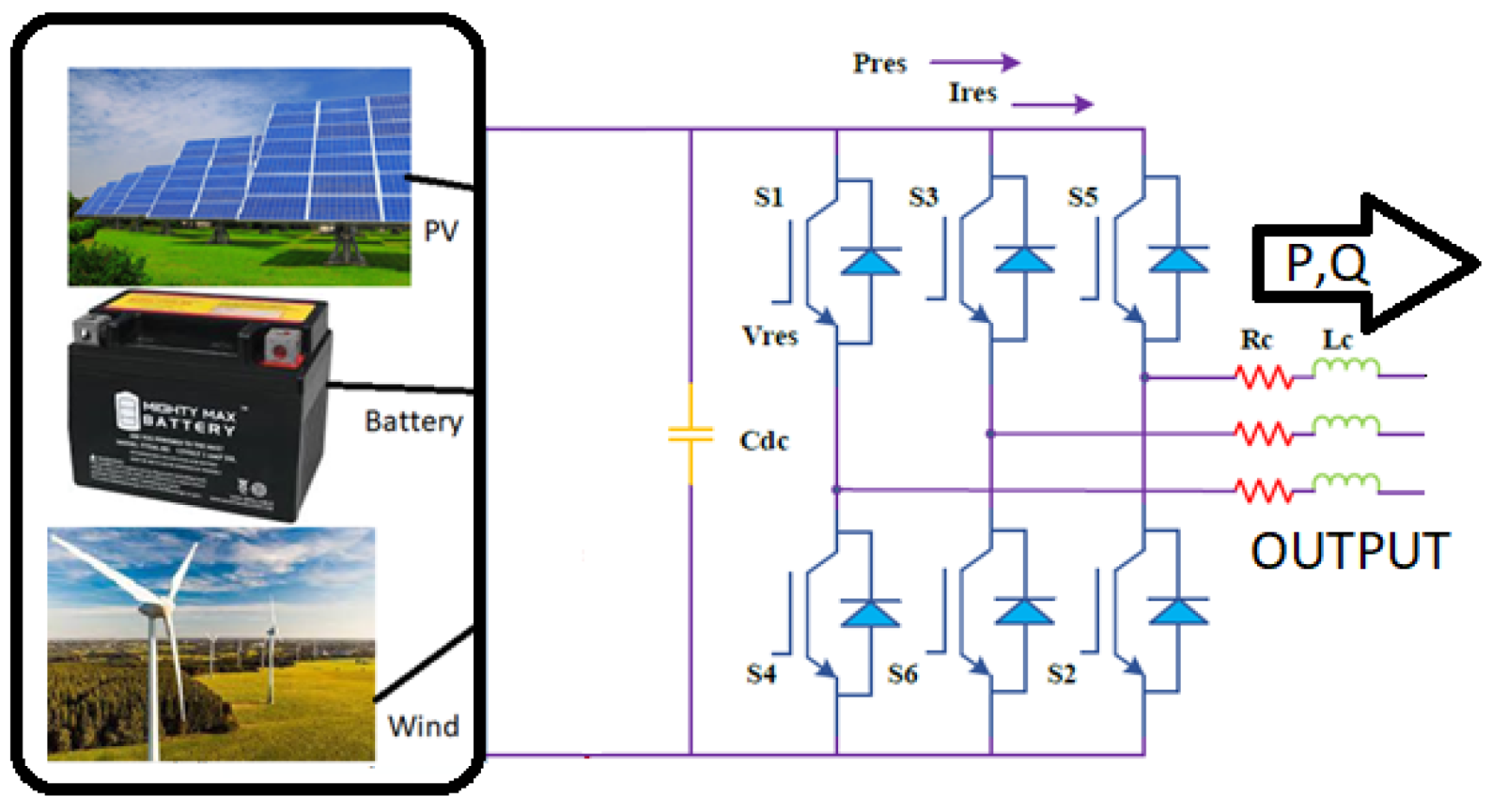
2.1. PV Microgrid Modelling
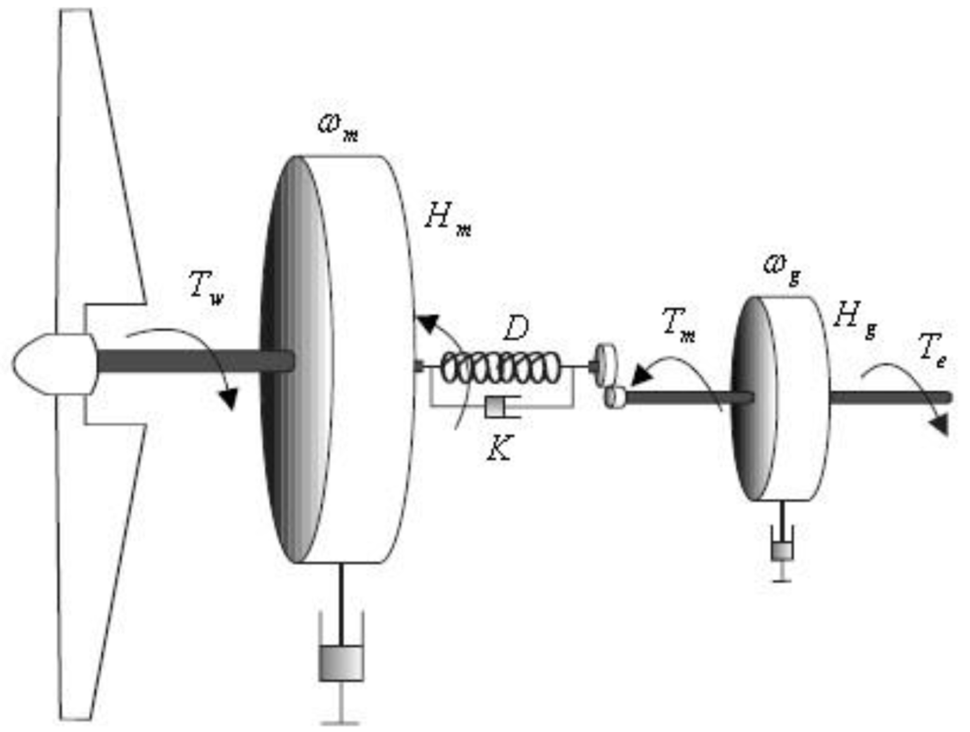
2.2. Wind Energy Microgrid Modelling
2.3. PV-Wind Hybrid Systems
2.4. Review for Microgrid Control Strategies
2.5. Mathematical Model for Controlling Inverter
2.6. Implementation of Inverter Tuning Control Approach
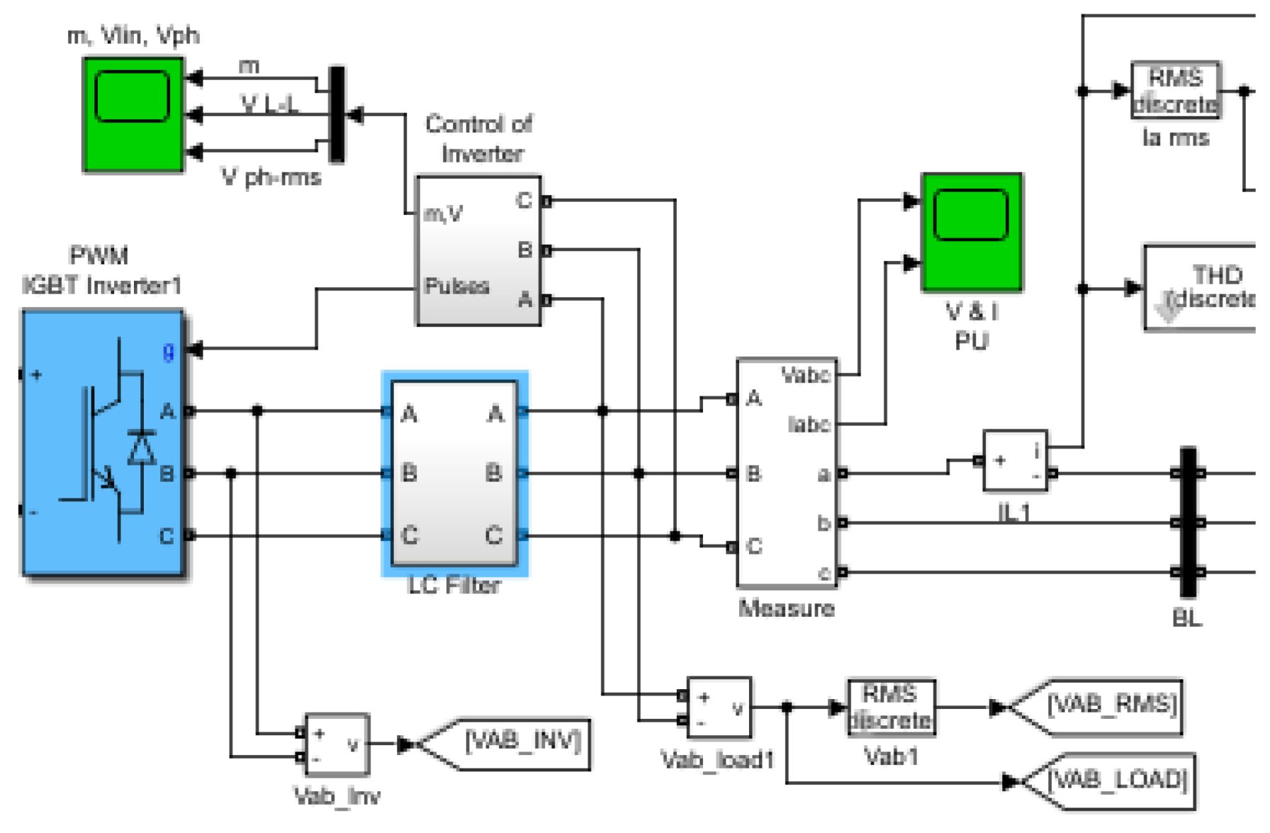
3. Application of Inverter Control (IC) Technique for Power Quality Enhancement
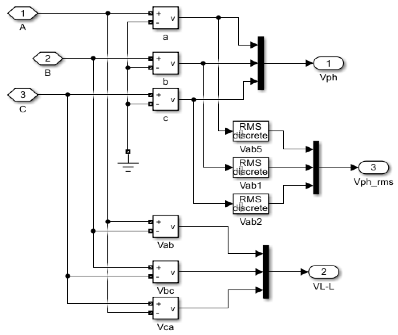
3.1. Control of the Inverter
3.2. Control of the Inverter
4. Application of Artificial Neural Network (ANN) Technique for Power Quality Enhancement
4.1. Review for ANN Control Strategies in Microgrids
4.2. Adoption for ANN in PV-Wind Hybrid Systems
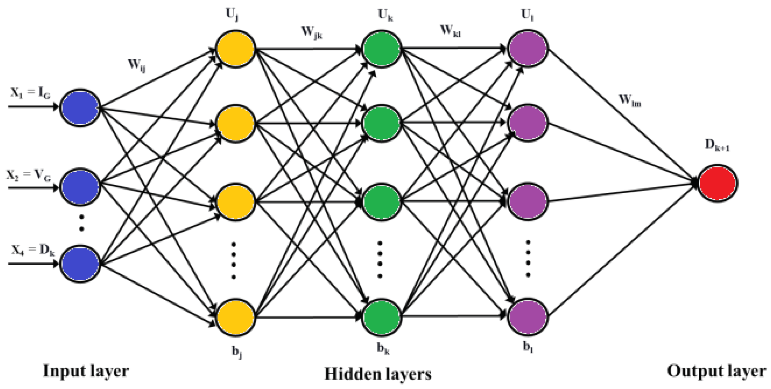
4.3. Mathematical Model for Controlling ANN in a PV-Wind Hybrid Systems
4.3.1. Gradient Descent
4.3.2. Derivative of Sigmoid Function
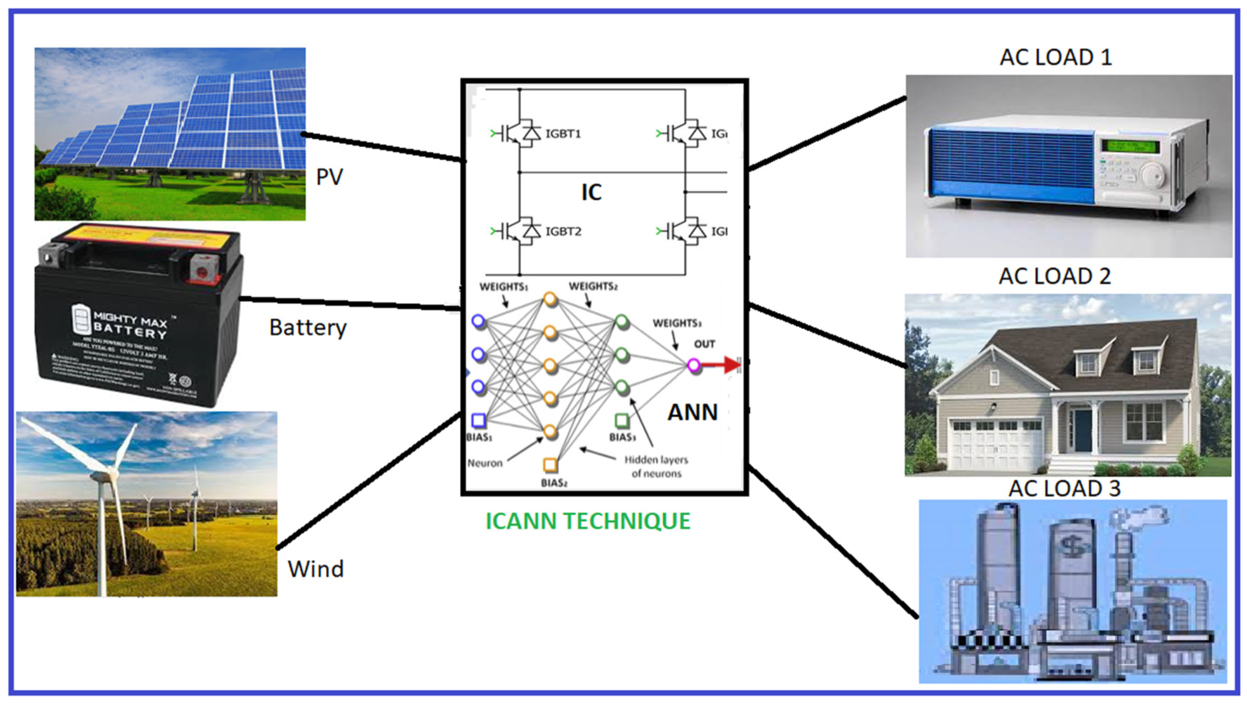
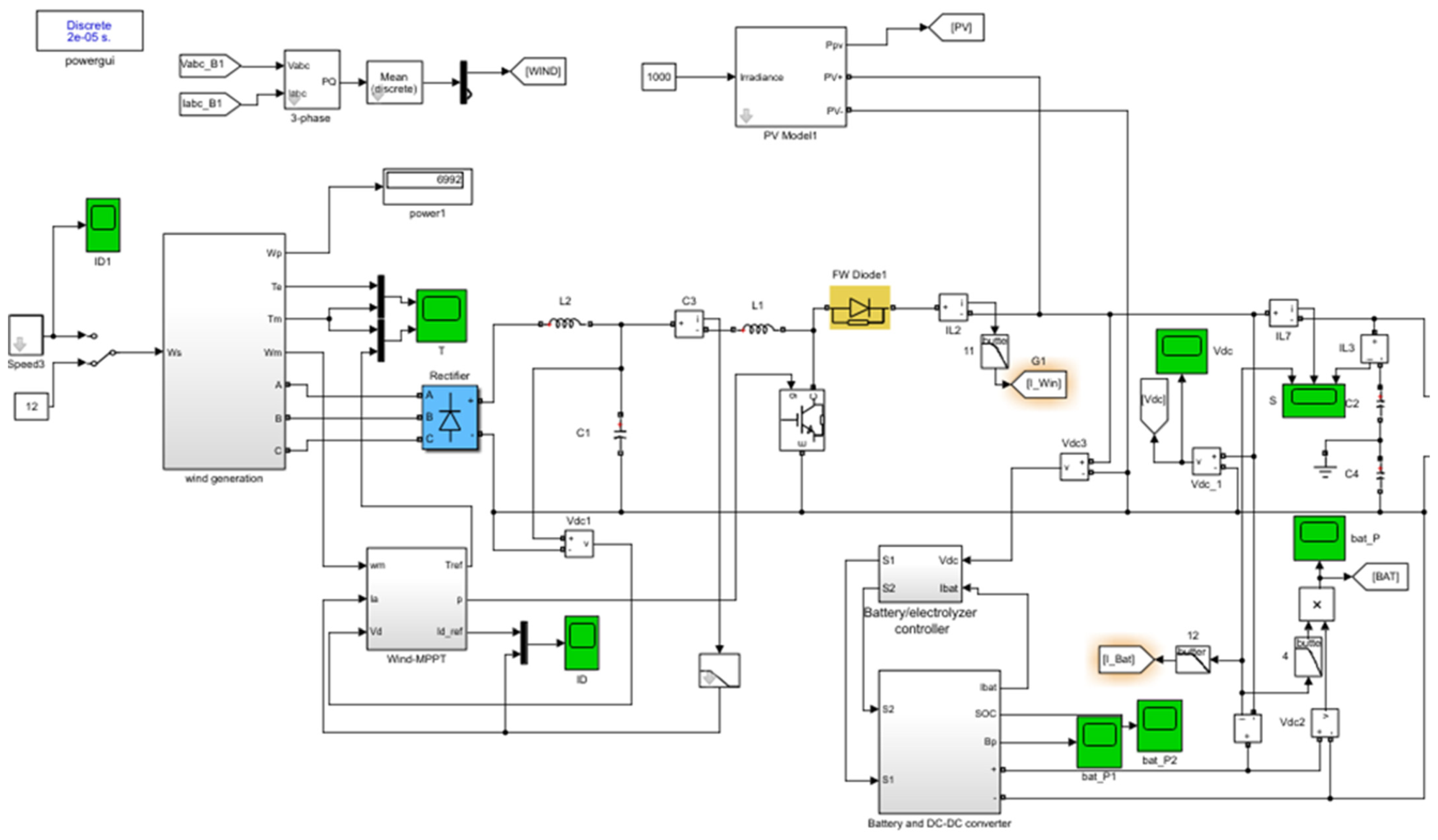
4.3.3. Application and Modelling of ICANN in PV-Wind Hybrid Systems
5. Simulation and Results
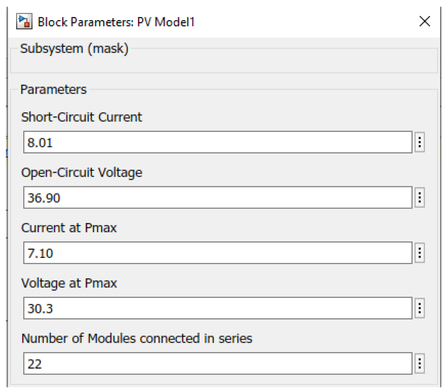
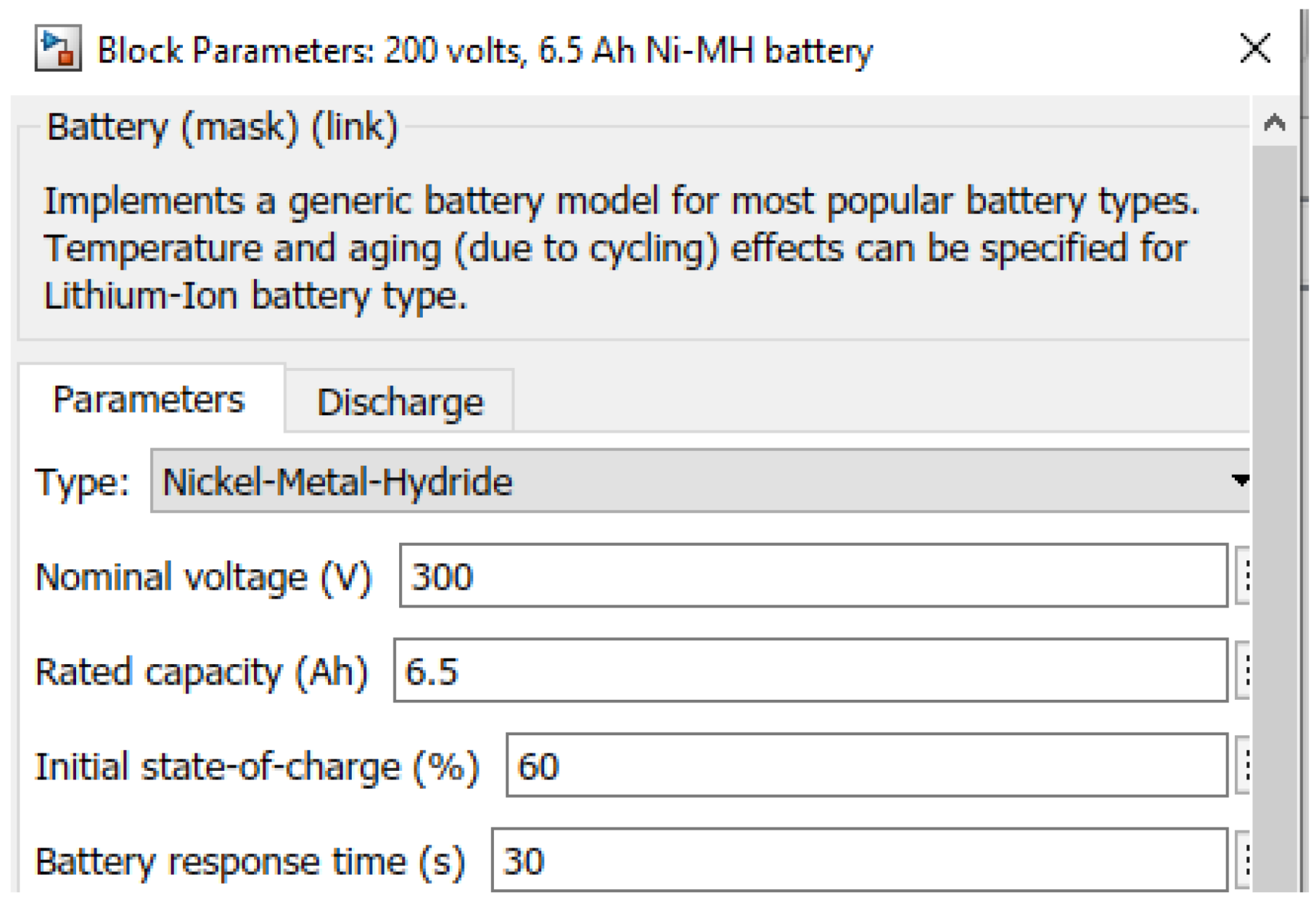
5.1. System Parameters
5.2. Case 1: Wind Turbine Internal Analysis
5.3. Case 2: No Phase Condition
5.4. Case 3: Data Inspector Power Quality Analysis
6. Conclusions and Future Outlook
Author Contributions
Funding
Data Availability Statement
Acknowledgments
Conflicts of Interest
References
- Salim, H.K.; Padfield, R.; Hansen, S.B.; Mohamad, S.E.; Yuzir, A.; Syayuti, K.; Tham, M.H.; Papargyropoulou, E. Global trends in environmental management system and ISO14001 research. J. Clean. Prod. 2018, 170, 645–653. [Google Scholar] [CrossRef]
- Simon, C.A. Alternative Energy: Political, Economic, and Social Feasibility; Rowman & Littlefield Publishers: Lanham, MD, USA, 2020. [Google Scholar]
- Ediger, V.Ş. An integrated review and analysis of multi-energy transition from fossil fuels to renewables. Energy Procedia 2019, 156, 2–6. [Google Scholar] [CrossRef]
- Zulu, M.; Ojo, E. Power Flow and Fault Analysis Simulation For A PV/Wind Hybrid DC Microgrid. In Proceedings of the 2022 30th Southern African Universities Power Engineering Conference (SAUPEC), Durban, South Africa, 25–27 January 2022; IEEE: Washington, DC, USA, 2022; pp. 1–6. [Google Scholar]
- Kumar, M. Social, economic, and environmental impacts of renewable energy resources. In Wind Solar Hybrid Renewable Energy System; IntechOpen: Rijeka, Croatia, 2020; Volume 1. [Google Scholar]
- Murdock, H.E.; Gibb, D.; André, T.; Sawin, J.L.; Brown, A.; Ranalder, L.; Collier, U.; Dent, C.; Epp, B.; Hareesh Kumar, C. Renewables 2021-Global Status Report. 2021. Available online: https://www.ren21.net/wp-content/uploads/2019/05/GSR2021_Full_Report.pdf (accessed on 26 May 2025).
- Vinuesa, R.; Azizpour, H.; Leite, I.; Balaam, M.; Dignum, V.; Domisch, S.; Felländer, A.; Langhans, S.D.; Tegmark, M.; Fuso Nerini, F. The role of artificial intelligence in achieving the Sustainable Development Goals. Nat. Commun. 2020, 11, 233. [Google Scholar] [CrossRef] [PubMed]
- Alipour, R.; Alipour, R.; Fardian, F.; Koloor, S.S.R.; Petrů, M. Performance improvement of a new proposed Savonius hydrokinetic turbine: A numerical investigation. Energy Rep. 2020, 6, 3051–3066. [Google Scholar] [CrossRef]
- Buonocore, J.J.; Choma, E.; Villavicencio, A.H.; Spengler, J.D.; Koehler, D.A.; Evans, J.S.; Lelieveld, J.; Klop, P.; Sanchez-Pina, R. Metrics for the sustainable development goals: Renewable energy and transportation. Palgrave Commun. 2019, 5, 136. [Google Scholar] [CrossRef]
- Swain, R.B.; Karimu, A. Renewable electricity and sustainable development goals in the EU. World Dev. 2020, 125, 104693. [Google Scholar] [CrossRef]
- Ojo, E.E.; Zulu, M.L.; Akinrinde, A.O. The Modelling and Simulation Of Power Flow and Fault Analysis For A Hybrid DC Microgrid. In Proceedings of the 2021 IEEE PES/IAS PowerAfrica, Nairobi, Kenya, 23–27 August 2021; IEEE: Washington, DC, USA, 2021; pp. 1–5. [Google Scholar]
- Pogaku, N.; Prodanovic, M.; Green, T.C. Modeling, analysis and testing of autonomous operation of an inverter-based microgrid. IEEE Trans. Power Electron. 2007, 22, 613–625. [Google Scholar] [CrossRef]
- Buraimoh, E.; Davidson, I. Investigation of the low voltage ride-through of inverter using virtual inertia methods in microgrid. Int. J. Eng. Res. Afr. 2019, 44, 200–212. [Google Scholar] [CrossRef]
- Buraimoh, E.; Davidson, I.E. Comparative Analysis of the Fault Ride-Through Capabilities of the VSG Methods of Microgrid Inverter Control under Faults. In Proceedings of the 2019 Southern African Universities Power Engineering Conference/Robotics and Mechatronics/Pattern Recognition Association of South Africa (SAUPEC/RobMech/PRASA), Bloemfontein, South Africa, 28–30 January 2019; IEEE: Washington, DC, USA, 2019; pp. 400–405. [Google Scholar]
- Diaz, G.; Gonzalez-Moran, C.; Gomez-Aleixandre, J.; Diez, A. Composite loads in stand-alone inverter-based microgrids—Modeling procedure and effects on load margin. IEEE Trans. Power Syst. 2009, 25, 894–905. [Google Scholar] [CrossRef]
- Hao, M.; Zhen, X. A control strategy for voltage source inverter adapted to multi—Mode operation in microgrid. In Proceedings of the 2017 36th Chinese Control Conference (CCC), Dalian, China, 26–28 July 2017; IEEE: Washington, DC, USA, 2017; pp. 9163–9168. [Google Scholar]
- Fazendeiro, L.M.; Simões, S.G. Historical variation of IEA energy and CO2 emission projections: Implications for future energy modeling. Sustainability 2021, 13, 7432. [Google Scholar] [CrossRef]
- Rocabert, J.; Luna, A.; Blaabjerg, F.; Rodriguez, P. Control of power converters in AC microgrids. IEEE Trans. Power Electron. 2012, 27, 4734–4749. [Google Scholar] [CrossRef]
- Kaviri, S.M.; Pahlevani, M.; Jain, P.; Bakhshai, A. A review of AC microgrid control methods. In Proceedings of the 2017 IEEE 8th International Symposium on Power Electronics for Distributed Generation Systems (PEDG), Florianopolis, Brazil, 17–20 April 2017; IEEE: Washington, DC, USA, 2017; pp. 1–8. [Google Scholar]
- Wu, D.; Tang, F.; Dragicevic, T.; Vasquez, J.C.; Guerrero, J.M. Autonomous active power control for islanded ac microgrids with photovoltaic generation and energy storage system. IEEE Trans. Energy Convers. 2014, 29, 882–892. [Google Scholar] [CrossRef]
- Elrayyah, A.; Sozer, Y.; Elbuluk, M. Microgrid-connected PV-based sources: A novel autonomous control method for maintaining maximum power. IEEE Ind. Appl. Mag. 2014, 21, 19–29. [Google Scholar] [CrossRef]
- Elrayyah, A.; Sozer, Y.; Elbuluk, M.E. Modeling and control design of microgrid-connected PV-based sources. IEEE J. Emerg. Sel. Top. Power Electron. 2014, 2, 907–919. [Google Scholar] [CrossRef]
- Du, W.; Jiang, Q.; Erickson, M.J.; Lasseter, R.H. Voltage-source control of PV inverter in a CERTS microgrid. IEEE Trans. Power Deliv. 2014, 29, 1726–1734. [Google Scholar] [CrossRef]
- Patil, M.; Deshpande, A. Design and simulation of perturb and observe maximum power point tracking using matlab/simulink. In Proceedings of the 2015 International Conference on Industrial Instrumentation and Control (ICIC), Pune, India, 28–30 May 2015; IEEE: Washington, DC, USA, 2015; pp. 1345–1349. [Google Scholar]
- Tsai, H.-L.; Tu, C.-S.; Su, Y.-J. Development of generalized photovoltaic model using MATLAB/SIMULINK. In Proceedings of the World Congress on Engineering and Computer Science, San Francisco, CA, USA, 22–24 October 2008; pp. 1–6. [Google Scholar]
- Oi, A. Design and Simulation of Photovoltaic Water Pumping System. Ph.D. Thesis, California Polytechnic State University, San Luis Obispo, CA, USA, 2005. [Google Scholar]
- Masters, G.M. Renewable and Efficient Electric Power Systems; John Wiley & Sons: Hoboken, NJ, USA, 2013. [Google Scholar]
- Zhao, J.; Graves, K.; Wang, C.; Liao, G.; Yeh, C.-P. A hybrid electric/hydro storage solution for standalone photovoltaic applications in remote areas. In Proceedings of the 2012 IEEE Power and Energy Society General Meeting, San Diego, CA, USA, 22–26 July 2012; IEEE: Washington, DC, USA, 2012; pp. 1–6. [Google Scholar]
- Salimath, G.; Singh, N.K.; Badge, S.S. Coordination and performance analysis of pumped hydro storage system integrated with solar, wind hybrid system. In Proceedings of the 2017 International Conference on Energy, Communication, Data Analytics and Soft Computing (ICECDS), Chennai, India, 1–2 August 2017; IEEE: Washington, DC, USA, 2017; pp. 160–164. [Google Scholar]
- Boukhezzar, B.; Lupu, L.; Siguerdidjane, H.; Hand, M. Multivariable control strategy for variable speed, variable pitch wind turbines. Renew. Energy 2007, 32, 1273–1287. [Google Scholar] [CrossRef]
- Chung, I.-Y.; Liu, W.; Cartes, D.A.; Schoder, K. Control parameter optimization for a microgrid system using particle swarm optimization. In Proceedings of the 2008 IEEE International Conference on Sustainable Energy Technologies, Singapore, 24–27 November 2008; IEEE: Washington, DC, USA, 2008; pp. 837–842. [Google Scholar]
- Antoniadou-Plytaria, K.E.; Kouveliotis-Lysikatos, I.N.; Georgilakis, P.S.; Hatziargyriou, N.D. Distributed and decentralized voltage control of smart distribution networks: Models, methods, and future research. IEEE Trans. Smart Grid 2017, 8, 2999–3008. [Google Scholar] [CrossRef]
- Sahoo, S.K.; Sinha, A.K.; Kishore, N. Control techniques in AC, DC, and hybrid AC–DC microgrid: A review. IEEE J. Emerg. Sel. Top. Power Electron. 2017, 6, 738–759. [Google Scholar] [CrossRef]
- Bidram, A.; Nasirian, V.; Davoudi, A.; Lewis, F.L. Cooperative Synchronization in Distributed Microgrid Control; Springer: Berlin/Heidelberg, Germany, 2017. [Google Scholar]
- Russell, S.J. Artificial Intelligence A Modern Approach; Pearson Education, Inc.: New York, NY, USA, 2010. [Google Scholar]
- Hug, G.; Kar, S.; Wu, C. Consensus+ innovations approach for distributed multiagent coordination in a microgrid. IEEE Trans. Smart Grid 2015, 6, 1893–1903. [Google Scholar] [CrossRef]
- Kouveliotis-Lysikatos, I.N.; Koukoula, D.I.; Hatziargyriou, N.D. A double-layered fully distributed voltage control method for active distribution networks. IEEE Trans. Smart Grid 2017, 10, 1465–1476. [Google Scholar] [CrossRef]
- Guo, F.; Wen, C.; Song, Y.-D. Distributed Control and Optimization Technologies in Smart Grid Systems; CRC Press: Boca Raton, FL, USA, 2017. [Google Scholar]
- Paquin, J.-N.; Moyen, J.; Dumur, G.; Lapointe, V. Real-time and off-line simulation of a detailed wind farm model connected to a multi-bus network. In Proceedings of the 2007 IEEE Canada Electrical Power Conference, Montreal, QC, Canada, 25–26 October 2007; IEEE: Washington, DC, USA, 2007; pp. 145–152. [Google Scholar]
- Golroodbari, S.; Vaartjes, D.; Meit, J.; Van Hoeken, A.; Eberveld, M.; Jonker, H.; Van Sark, W. Pooling the cable: A techno-economic feasibility study of integrating offshore floating photovoltaic solar technology within an offshore wind park. Sol. Energy 2021, 219, 65–74. [Google Scholar] [CrossRef]
- Rahman, A.U.; Syed, I.; Ullah, M. Small-signal stability criteria in AC distribution systems—A review. Electronics 2019, 8, 216. [Google Scholar] [CrossRef]
- Zhang, M.; Han, Y.; Liu, Y.; Zalhaf, A.S.; Zhao, E.; Mahmoud, K.; Darwish, M.M.; Blaabjerg, F. Multi-timescale modeling and dynamic stability analysis for sustainable microgrids: State-of-the-art and perspectives. Prot. Control Mod. Power Syst. 2024, 9, 1–35. [Google Scholar] [CrossRef]
- Gullì, F.; Balbo, A.L. The impact of intermittently renewable energy on Italian wholesale electricity prices: Additional benefits or additional costs? Energy Policy 2015, 83, 123–137. [Google Scholar] [CrossRef]
- De Vries, B.J.; Van Vuuren, D.P.; Hoogwijk, M.M. Renewable energy sources: Their global potential for the first-half of the 21st century at a global level: An integrated approach. Energy Policy 2007, 35, 2590–2610. [Google Scholar] [CrossRef]
- Broughel, A.E.; Hampl, N. Community financing of renewable energy projects in Austria and Switzerland: Profiles of potential investors. Energy Policy 2018, 123, 722–736. [Google Scholar] [CrossRef]
- Guelpa, E.; Bischi, A.; Verda, V.; Chertkov, M.; Lund, H. Towards future infrastructures for sustainable multi-energy systems: A review. Energy 2019, 184, 2–21. [Google Scholar] [CrossRef]
- Jurasz, J.; Canales, F.; Kies, A.; Guezgouz, M.; Beluco, A. A review on the complementarity of renewable energy sources: Concept, metrics, application and future research directions. Sol. Energy 2020, 195, 703–724. [Google Scholar] [CrossRef]
- Yallamilli, R.S.; Vedulla, L.K.; Mishra, M.K. Cost savings oriented microgrid control strategy considering battery degradation. In Proceedings of the 2018 7th International Conference on Renewable Energy Research and Applications (ICRERA), Paris, France, 14–17 October 2018; IEEE: Washington, DC, USA, 2018; pp. 661–666. [Google Scholar]
- Goud, S.; Rao, B.L. PV-Wind Integrated Grid with P&O and PSO MPPT Techniques. Int. J. Recent Technol. Eng. (IJRTE) 2019, 8, 3217–3224. [Google Scholar]
- Goud, B.S.; Varma, P.S.; Rao, B.L.; Reddy, M.S.K.; Pandian, A.; Reddy, C.R. Cuckoo search optimization based MPPT for integrated DFIG-wind energy system. In Proceedings of the 2020 International Conference on Decision Aid Sciences and Application (DASA), Sakheer, Bahrain, 8–9 November 2020; IEEE: Washington, DC, USA, 2020; pp. 636–639. [Google Scholar]
- Srikanth Goud, B.; Rao, B.L.; Devi, B.N.; Kumar, K.S.; Keerthi, N. Review on optimization techniques employed in distribution generation. J. Crit. Rev. 2020, 7, 639–645. [Google Scholar]
- Uzair, M.; Li, L.; Zhu, J.G.; Eskandari, M. A protection scheme for AC microgrids based on multi-agent system combined with machine learning. In Proceedings of the 2019 29th Australasian Universities Power Engineering Conference (AUPEC), Nadi, Fiji, 26–29 November 2019; IEEE: Washington, DC, USA, 2019; pp. 1–6. [Google Scholar]
- Singh, P.; Lather, J.S. Artificial neural network-based dynamic power management of a DC microgrid: A hardware-in-loop real-time verification. Int. J. Ambient. Energy 2022, 43, 1730–1738. [Google Scholar] [CrossRef]
- Shokoohi, S.; Golshannavaz, S.; Khezri, R.; Bevrani, H. Intelligent secondary control in smart microgrids: An on-line approach for islanded operations. Optim. Eng. 2018, 19, 917–936. [Google Scholar] [CrossRef]
- Khooban, M.H.; Gheisarnejad, M. A novel deep reinforcement learning controller based type-II fuzzy system: Frequency regulation in microgrids. IEEE Trans. Emerg. Top. Comput. Intell. 2020, 5, 689–699. [Google Scholar] [CrossRef]
- Vigneysh, T.; Kumarappan, N. Artificial neural network based droop-control technique for accurate power sharing in an islanded microgrid. Int. J. Comput. Intell. Syst. 2016, 9, 827–838. [Google Scholar] [CrossRef]
- Dong, W.Z.; Li, S.H.; Fu, X.G. Artificial neural network control of a standalone DC microgrid. In Proceedings of the 2018 Clemson university power systems conference (PSC), Charleston, SC, USA, 4–7 September 2018; IEEE: Washington, DC, USA, 2018; pp. 1–5. [Google Scholar]
- Elsayed, M.; Erol-Kantarci, M.; Kantarci, B.; Wu, L.; Li, J. Low-latency communications for community resilience microgrids: A reinforcement learning approach. IEEE Trans. Smart Grid 2019, 11, 1091–1099. [Google Scholar] [CrossRef]
- Saadatmand, S.; Nia, M.S.S.; Shamsi, P.; Ferdowsi, M. Dual heuristic dynamic programing control of grid-connected synchronverters. In Proceedings of the 2019 North American Power Symposium (NAPS), Wichita, KS, USA, 13–15 October 2019; IEEE: Washington, DC, USA, 2019; pp. 1–6. [Google Scholar]
- Kim, H.; Ahmad, A.; Hwang, J.; Baqa, H.; Gall, F.L.; Ortega, M.A.R. IoT-TaaS: Towards a prospective IoT testing framework. IEEE Access 2018, 6, 15480–15493. [Google Scholar] [CrossRef]
- Moayedi, S.; Davoudi, A. Distributed tertiary control of DC microgrid clusters. IEEE Trans. Power Electron. 2015, 31, 1717–1733. [Google Scholar] [CrossRef]
- Shang, L.; Li, P.; Li, Z. Low voltage ride through control method of photovoltaic grid-connected inverter based on model current predictive control. In Proceedings of the 2018 Chinese Control and Decision Conference (CCDC), Shenyang, China, 9–11 June 2018; IEEE: Washington, DC, USA, 2018; pp. 5209–5214. [Google Scholar]


| Ref. | AI Technique | Control Strategy | Objectives | Grid Connect (On/Off/Both) |
|---|---|---|---|---|
| [53] | ANN | Centralized | Voltage and frequency regulation | Off |
| [54] | ANN | Centralized | Frequency regulation | Off |
| [55] | ANFIS | Centralized | Reactive Power Sharing | Off |
| [56] | ANN | Distributed | Voltage and frequency regulation | Off |
| [57] | ANN | Distributed | Frequency regulation | Off |
| [58] | ANN | Distributed | Voltage and frequency regulation | Off |
| [59] | ANN | Not specified | Optimal control | On |
| [60] | ANN | Not specified | Power quality control | On |
| Wind Generation | |
|---|---|
| Conditions | Outputs |
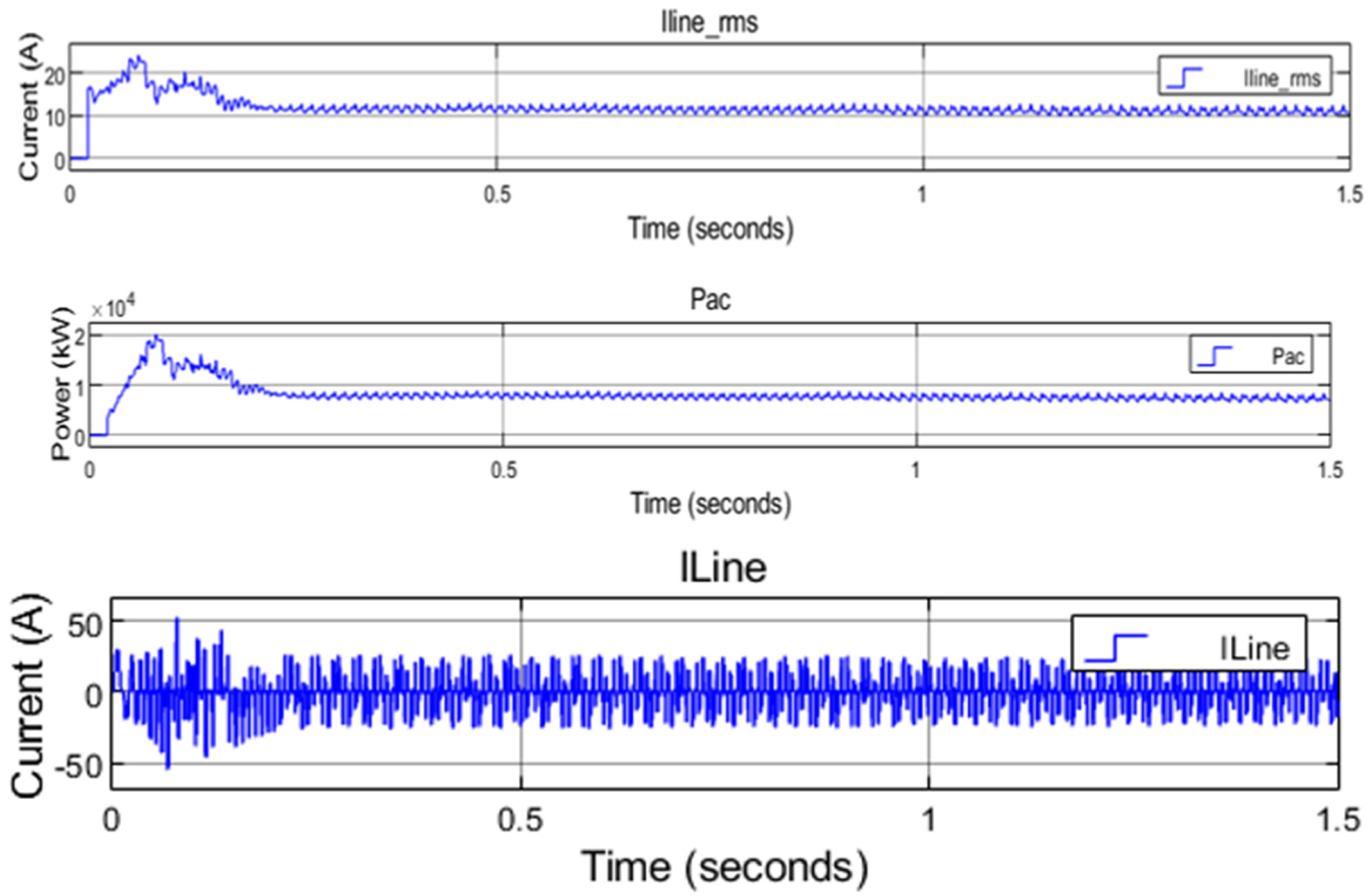
| RMS Line current (ILine_RMS), | 22 A |
| AC Power | 20,000 kW |
| Line current (ILine) | 25 A |
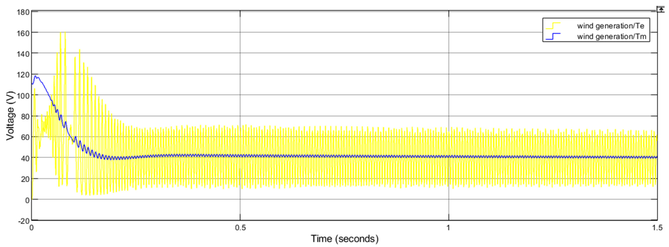
| Wind generation/Te with wind generation/Tm | Te = 70 V Tm = 40 V |
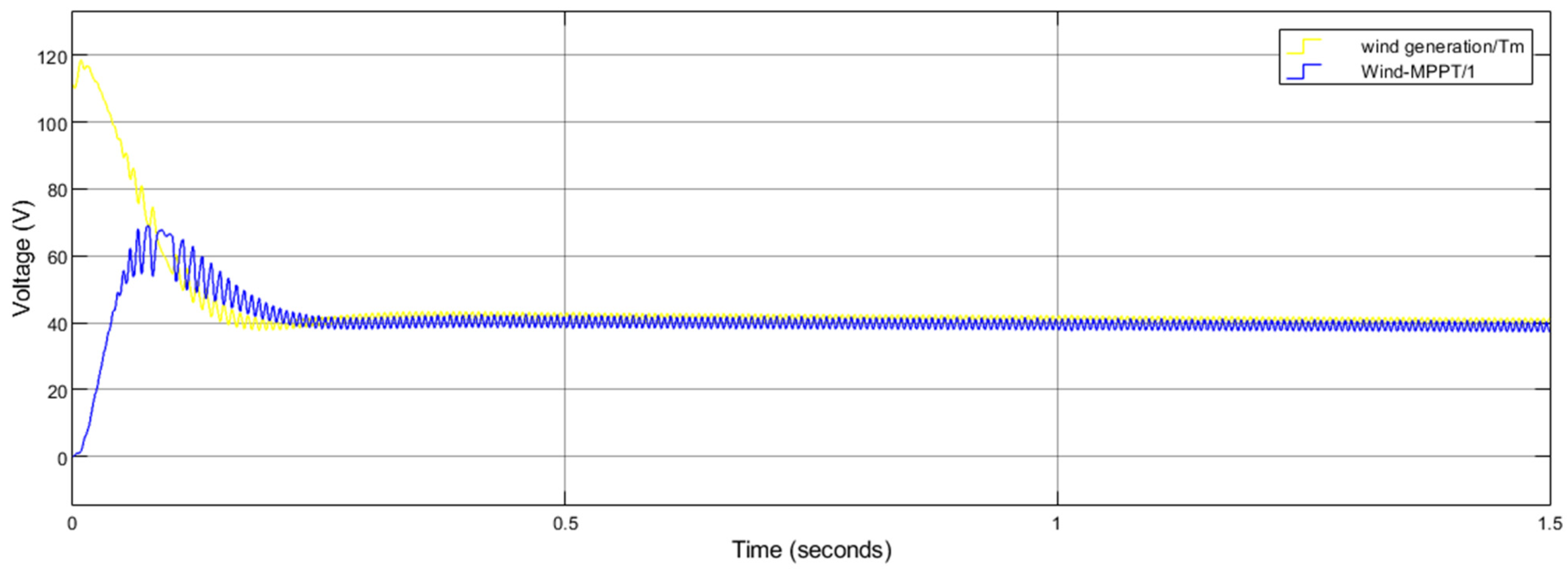
| Wind generation/Tm and wind MPPT/1 output during normal condition | Tm = 120 V MPPT/1 = 70 V Equilibrium = 40 V |
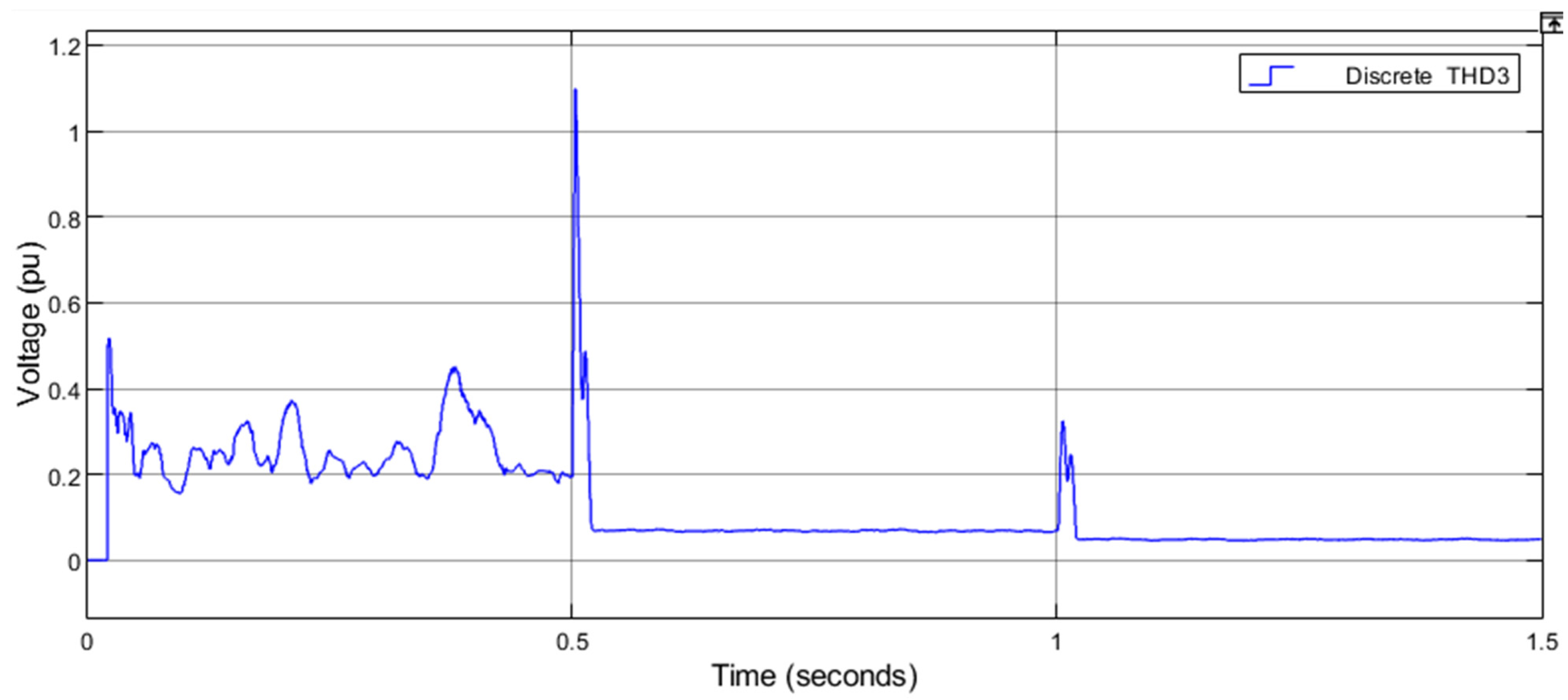
| Total Harmonic distortion 3 (THD3) | THD = 0.1 pu |
Disclaimer/Publisher’s Note: The statements, opinions and data contained in all publications are solely those of the individual author(s) and contributor(s) and not of MDPI and/or the editor(s). MDPI and/or the editor(s) disclaim responsibility for any injury to people or property resulting from any ideas, methods, instructions or products referred to in the content. |
© 2025 by the authors. Licensee MDPI, Basel, Switzerland. This article is an open access article distributed under the terms and conditions of the Creative Commons Attribution (CC BY) license (https://creativecommons.org/licenses/by/4.0/).
Share and Cite
Zulu, M.L.T.; Sarma, R.; Tiako, R. Enhancing Power Quality in a PV/Wind Smart Grid with Artificial Intelligence Using Inverter Control and Artificial Neural Network Techniques. Electricity 2025, 6, 35. https://doi.org/10.3390/electricity6020035
Zulu MLT, Sarma R, Tiako R. Enhancing Power Quality in a PV/Wind Smart Grid with Artificial Intelligence Using Inverter Control and Artificial Neural Network Techniques. Electricity. 2025; 6(2):35. https://doi.org/10.3390/electricity6020035
Chicago/Turabian StyleZulu, Musawenkosi Lethumcebo Thanduxolo, Rudiren Sarma, and Remy Tiako. 2025. "Enhancing Power Quality in a PV/Wind Smart Grid with Artificial Intelligence Using Inverter Control and Artificial Neural Network Techniques" Electricity 6, no. 2: 35. https://doi.org/10.3390/electricity6020035
APA StyleZulu, M. L. T., Sarma, R., & Tiako, R. (2025). Enhancing Power Quality in a PV/Wind Smart Grid with Artificial Intelligence Using Inverter Control and Artificial Neural Network Techniques. Electricity, 6(2), 35. https://doi.org/10.3390/electricity6020035