
Single-Level and Two-Level Circuit Solutions for Buck-Boost AC Voltage Regulators with Phase-by-Phase Switches

 ,
,  , and
, and
Abstract
1. Introduction
- (1)
- Correction of the output voltage waveform;
- (2)
- Protection against overheating and short circuits in the load supply circuit;
- (3)
- Protective shutdown of the device at unacceptable input voltage values (the required threshold along the upper and lower boundaries can be set by the user independently);
- (4)
- Suppression of RF and pulse interference by the output filter;
- (5)
- The ability to set the required output voltage values different than the standard ones;
- (6)
- The possibility of implementing parameter monitoring and remote control of the stabilizer.
2. Circuit Design of AC Voltage Regulators with Phase-by-Phase Switches
3. Mathematical Model
4. Simulation
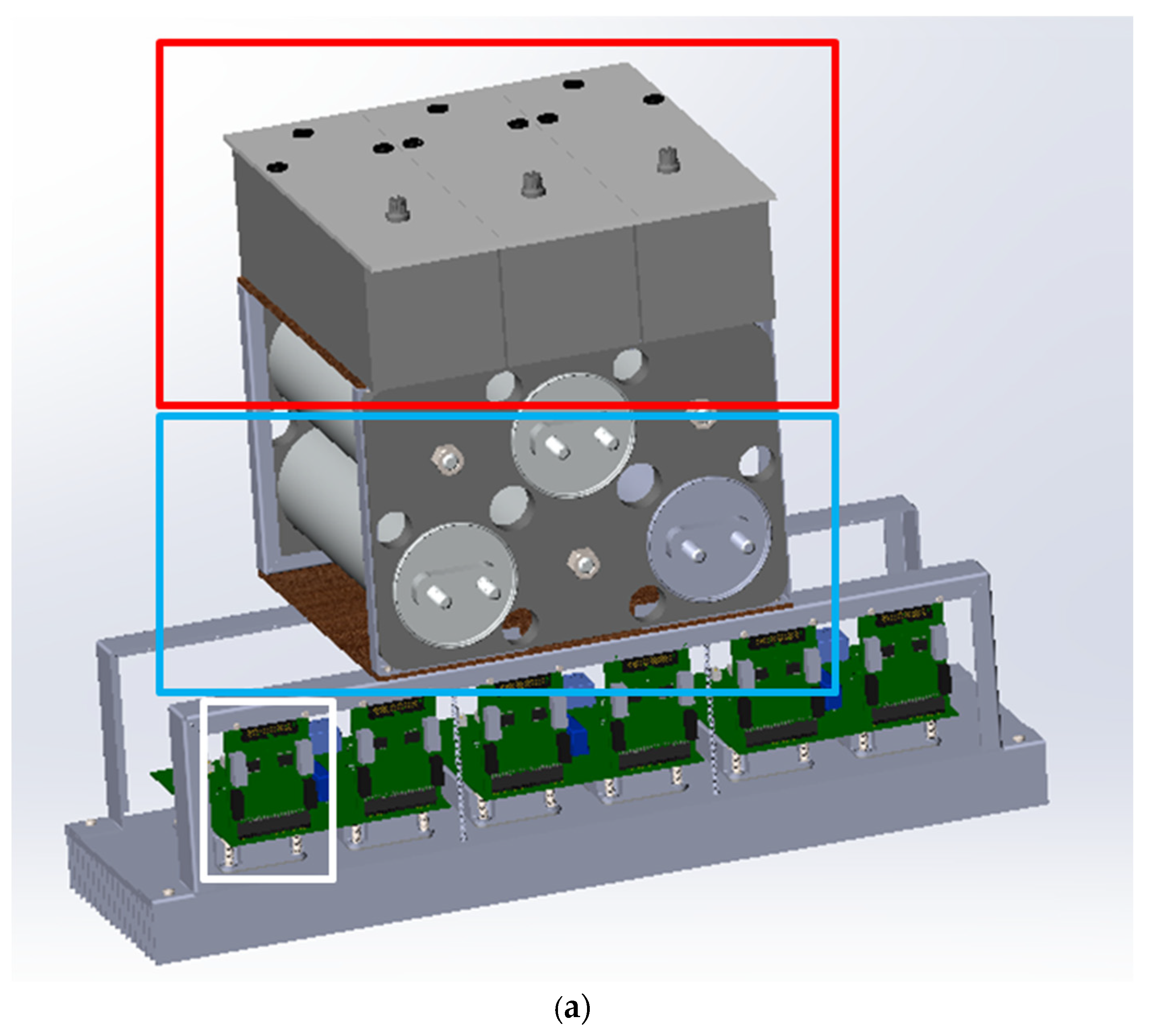
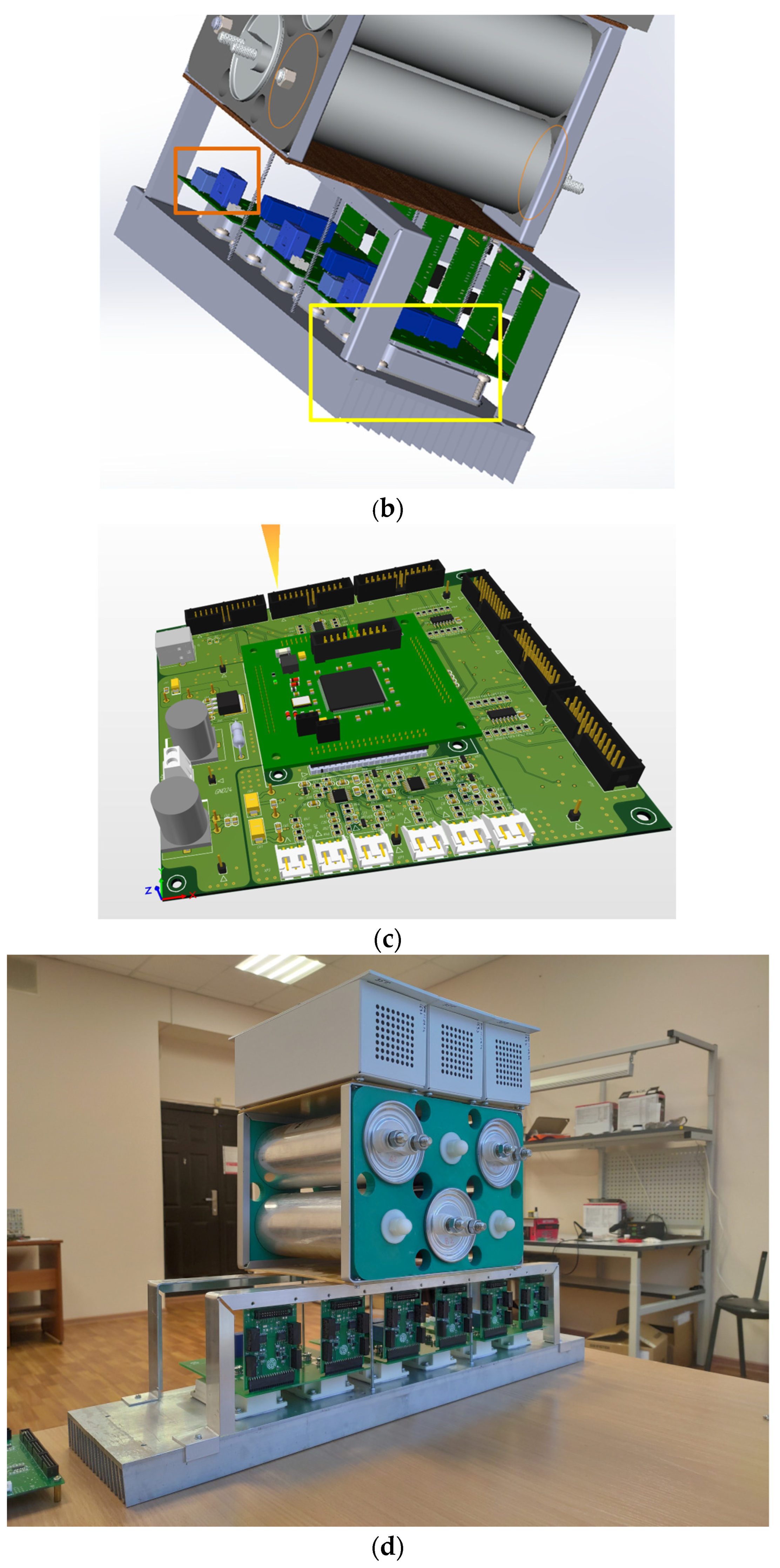
5. Experiment
6. Conclusions
Author Contributions
Funding
Data Availability Statement
Conflicts of Interest
References
- Sazhenkov, V. Soft starters and frequency converters. Schneider Electric Technical Collection. Available online: https://en-res.ru/wp-content/uploads/2012/12/v38.pdf?ysclid=m709a0lgxr496516420 (accessed on 6 June 2023).
- Brescia, E.; Vergallo, P.; Celik, I. Parameter Identification of PMSMs Considering VSI Nonlinearity with Coupled Adaline NNs. In Proceedings of the 2023 IEEE 3rd International Conference on Power, Electronics and Computer Applications (ICPECA), IEEE, Shenyang, China, 29–31 January 2023; pp. 259–265. [Google Scholar]
- Brescia, E.; Serafino, P.; Cascella, D.; Comitangelo, G.; Conte, G.; Chieco, L. Automated Parameter Identification of SPMSMs Based on Two Steady States Using Cloud Computing Resources. In Proceedings of the 2021 International Conference on Electrical, Computer and Energy Technologies (ICECET), IEEE, Cape Town, South Africa, 9–10 December 2021; pp. 1–6. [Google Scholar]
- Brescia, E.; Palmieri, M.; Massenio, P.R.; Cascella, G.L.; Cupertino, F. Cogging Torque Suppression of Modular Permanent Magnet Machines Using a Semi-Analytical Approach and Artificial Intelligence. IEEE Access 2023, 11, 39405–39417. [Google Scholar] [CrossRef]
- Brahmbhatt, H.; Patel, A.; Patel, V.; Lakhani, H. A Novel Control Strategy of Thyristorised Medium Voltage Soft Starter for Induction Motor Drives. In Proceedings of the 1st International Conference on Advances in Energy Conversion Technologies (ICAECT 2010), Manipal, India, 7–10 January 2010; pp. 1–5. [Google Scholar]
- Lakhani, H.; Patel, V.; Jamnani, J.G.; Jani, S. Design and simulation of controller for medium voltage thyristorised induction motor soft starter. In Proceedings of the 2009 International Conference for Technical Postgraduates (TECHPOS), IEEE, Kuala Lumpur, Malaysia, 14–15 December 2009; pp. 1–5. [Google Scholar]
- Wu, J.; Zhao, R.; Shang, Z. The design of soft starter for AC motors based on single neuron PI regulator. In Proceedings of the 2006 6th World Congress on Intelligent Control and Automation, IEEE, Dalian, China, 21–23 June 2006; Volume 1, pp. 3009–3013. [Google Scholar]
- Chen, X.; Li, H. Research and Simulation of Electromagnetic Voltage-Regulated Soft Starter Based on Predictive Control. In MATEC Web of Conferences; EDP Sciences: Les Ulis, France, 2018; Volume 232, p. 04040. [Google Scholar]
- Jakovlev, I. Mathematical model of operation of an asynchronous motor with a soft-start device based on an AC voltage regulator. Energy Syst. 2022, 7, 54–68. (In Russian) [Google Scholar] [CrossRef]
- Lopatkin, N.; Zinoviev, G.; Kharitonov, S. Inverter Asynchronous Electric Drive System with PAM and PWM Control. In Proceedings of the 2022 International Ural Conference on Electrical Power Engineering (UralCon), IEEE, Magnitogorsk, Russia, 23–25 September 2022; pp. 341–346. [Google Scholar]
- Zinoviev, G.S. Development of set of electric energy quality factors. In Proceedings of the 2018 XIV International Scientific-Technical Conference on Actual Problems of Electronics Instrument Engineering (APEIE), IEEE, Novosibirsk, Russia, 2–6 October 2018; pp. 44–47. [Google Scholar]
- Zinoviev, G. Definition of contributions of nonlinear consumers in total distortion of power line current. In Proceedings of the 2016 11th International Forum on Strategic Technology (IFOST), IEEE, Novosibirsk, Russia, 1–3 June 2016; pp. 154–156. [Google Scholar]
- Makarov, D.; Zinoviev, G.; Kharitonov, S. Analytical analysis of the variable frequency power system with shunt-connected voltage regulator. In Proceedings of the 2015 International Conference on Electrical Drives and Power Electronics (EDPE), IEEE, Tatranska Lomnica, Slovakia, 21–23 September 2015; pp. 482–487. [Google Scholar]
- Lipko, V.A.; Zinoviev, G.S. The family of extended power quality factors. In Proceedings of the 2015 16th International Conference of Young Specialists on Micro/Nanotechnologies and Electron Devices, IEEE, Erlagol, Russia, 29 June–3 July 2015; pp. 553–556. [Google Scholar]
- Zinoviev, G.S.; Sidorov, A.V.; Kharitonov, S.A. Three-phase AC voltage regulator as part of an autonomous system. In Proceedings of the 2014 12th International Conference on Actual Problems of Electronics Instrument Engineering (APEIE), Novosibirsk, Russia, 2–4 October 2014; pp. 762–765. [Google Scholar]
- Gorbunov, R.L.; Zinoviev, G.S. Three-phase transformerless AC-voltage converters with reduced number of switches. In Proceedings of the 2014 15th International Conference of Young Specialists on Micro/Nanotechnologies and Electron Devices (EDM), Novosibirsk, Russia, 30 June–4 July 2014; pp. 375–379. [Google Scholar]
- Sidorov, A.V.; Zinoviev, G.S. AC voltage regulator on the basis of the consecutive voltage regulator with PWM. In Proceedings of the 2013 14th International Conference of Young Specialists on Micro/Nanotechnologies and Electron Devices, Novosibirsk, Russia, 1–5 July 2013; pp. 369–373. [Google Scholar]
- Kosykh, E.; Udovichenko, A.; Lopatkin, N.; Zinoviev, G.; Grishanov, E.; Sarakhanova, R. Analysis of the Control System for a Soft Starter of an Induction Motor Based on a Multi-Zone AC Voltage Converter. Electronics 2023, 12, 56. [Google Scholar] [CrossRef]
- Report “Voltage Stabilizer System—Global Market Trajectory and Analytics” [Electronic Resource]. Available online: https://en-res.ru/wp-content/uploads/2012/12/v38.pdf?ysclid=m709a0lgxr496516420 (accessed on 7 February 2025).
- Shao, Y.; El-Kady, M.F.; Sun, J.; Li, Y.; Zhang, Q.; Zhu, M.; Wang, H.; Dunn, B.; Kaner, R.B. Design and mechanisms of asymmetric supercapacitors. Chem. Rev. 2018, 118, 9233–9280. [Google Scholar] [CrossRef] [PubMed]
- Šapurov, M.; Bleizgys, V.; Baskys, A.; Dervinis, A.; Bielskis, E.; Paulikas, S.; Paulauskas, N.; Macaitis, V. Asymmetric compensation of reactive power using thyristor-controlled reactors. Symmetry 2020, 12, 880. [Google Scholar] [CrossRef]
- Liu, W.; Tu, Q.; Chen, Z.; Li, X.; Luo, Y.; Jiao, S.; Wang, F. Short-circuit current calculation model for symmetrical two-core phase-shifting transformer. In Proceedings of the 2021 International Conference on Power System Technology (POWERCON), Haikou, China, 8–9 December 2021; pp. 2159–2165. [Google Scholar] [CrossRef]
- Song, P.; Zhang, Y.; Tang, Q.; Meng, Z. Control strategy of STATCOM for asymmetrical load compensation. In Proceedings of the 2016 China International Conference on Electricity Distribution (CICED), Xi’an, China, 10–13 August 2016; pp. 1–3. [Google Scholar] [CrossRef]
- Egorov, M.J. Improving the Quality of Electric Energy in Rural Networks of 0.38 kV by Developing a Device for Balancing and Stabilizing Phase Voltages. Ph.D. Thesis, Velikie Luki, Federal State Budgetary Educational Institution of Higher Education “Saint Petersburg State Agrarian University”, St Petersburg, Russia, 2018; 195p. (In Russian). [Google Scholar]
- Udovichenko, A.; Grishanov, E.; Kosykh, E.; Mekhtiyev, A. Analysis of Novel Energy-Efficient Converters to Ensure the Required Quality of Electrical Energy. Symmetry 2023, 15, 2092. [Google Scholar] [CrossRef]
- Zinoviev, G.S.; Levin, E.Y.; Obukhov, A.E.; Popov, V.I. Step-up and step-down regulators of alternating voltage and direct frequency converters. Electr. Eng. 2000, 11, 16–20. (In Russian) [Google Scholar]
- Zinoviev, G.S. Power Electronics: A Textbook in 2 Parts, 5th ed.; Revised and Supplemented; Limited Liability Company “YURAYT Publishing House”: Moscow, Russia, 2018; 390p. (In Russian) [Google Scholar]


| M/RAV Variants | LCC (50 V) | LCC (310 V) | C | CC | 2 Level LCC |
|---|---|---|---|---|---|
| 1 | 29% | 8.7% | 99% | 82% | 99% |
| 0.9 | 21.7% | 5.5% | 8% | 85% | 49% |
| 0.8 | 15.4% | 3.7% | 5.6% | 76% | 37% |
| 0.7 | 10.1% | 2.4% | 4.5% | 59% | 25% |
| 0.6 | 7.3% | 1.7% | 4% | 41% | 16.6% |
| 0.5 | 5.5% | 1.3% | 3.5% | 26% | 10.4% |
| 0.3 | 4.4% | 1% | 3.2% | 16% | 6.9% |
| 0.2 | 3.5% | 0.8% | 2.9% | 9.3% | 6.1% |
| 0.1 | 2.8% | 0.6% | 2.7% | 5.5% | 9.3% |
| 0 | 2.2% | 0.5% | 2.2% | 5.4% | 9.4% |
Disclaimer/Publisher’s Note: The statements, opinions and data contained in all publications are solely those of the individual author(s) and contributor(s) and not of MDPI and/or the editor(s). MDPI and/or the editor(s) disclaim responsibility for any injury to people or property resulting from any ideas, methods, instructions or products referred to in the content. |
© 2025 by the authors. Licensee MDPI, Basel, Switzerland. This article is an open access article distributed under the terms and conditions of the Creative Commons Attribution (CC BY) license (https://creativecommons.org/licenses/by/4.0/).
Share and Cite
Udovichenko, A.; Grishanov, E.; Kosykh, E.; Filippov, M.; Dybko, M. Single-Level and Two-Level Circuit Solutions for Buck-Boost AC Voltage Regulators with Phase-by-Phase Switches. Electricity 2025, 6, 6. https://doi.org/10.3390/electricity6010006
Udovichenko A, Grishanov E, Kosykh E, Filippov M, Dybko M. Single-Level and Two-Level Circuit Solutions for Buck-Boost AC Voltage Regulators with Phase-by-Phase Switches. Electricity. 2025; 6(1):6. https://doi.org/10.3390/electricity6010006
Chicago/Turabian StyleUdovichenko, Aleksey, Evgeniy Grishanov, Evgeniy Kosykh, Maksim Filippov, and Maksim Dybko. 2025. "Single-Level and Two-Level Circuit Solutions for Buck-Boost AC Voltage Regulators with Phase-by-Phase Switches" Electricity 6, no. 1: 6. https://doi.org/10.3390/electricity6010006
APA StyleUdovichenko, A., Grishanov, E., Kosykh, E., Filippov, M., & Dybko, M. (2025). Single-Level and Two-Level Circuit Solutions for Buck-Boost AC Voltage Regulators with Phase-by-Phase Switches. Electricity, 6(1), 6. https://doi.org/10.3390/electricity6010006