Abstract
The ongoing development of renewable energy and microgrid technologies has gradually transformed the conventional energy infrastructure and upgraded it into a modernized system with more distributed generation and localized energy storage options. Compared with power grids utilizing synchronous generation, inverter-based networks cannot physically provide large amounts of inertia, which means that more advanced and extensive studies regarding stability considerations are required for such systems. Therefore, appropriate analytical methods are needed for the voltage stability analysis of renewable-dominated power systems, which incorporate a large number of inverters and distributed energy sources. This paper provides a comprehensive literature review of voltage stability analyses of power systems with high levels of renewable energy penetration. A series of generalized evaluation schemes and improvement methods relating to the voltage stability of power systems integrated with various distributed energy resources are discussed. The existing voltage stability analysis methods and corresponding simulation verification models for microgrids are also reviewed in a systematic manner. The traditional and improved voltage stability analysis methods are reviewed according to the microgrid operation mode, the types of distributed generators, and the microgrid configurations. Moreover, the voltage stability indices, which play a crucial role in voltage stability assessments, are critically evaluated in terms of the applicable conditions. The associated modeling and simulation techniques are also presented and discussed. This contribution presents guidelines for voltage stability analysis and instability mitigation methods for modern renewable-rich power systems.
1. Introduction
Voltage stability has become a progressively significant issue in modern power distribution networks due to increasing load demands and distributed generation penetration. Compared with traditional power systems, the voltage control capability of renewable energy power generation systems is limited [1,2,3]. As traditional synchronous generators are gradually being replaced by inverter-based renewable energy generation systems, the stability, system frequency, and voltage of power systems are being challenged [4]. When the voltage control capability of a specific power system is lower than a certain range, the power system becomes unstable. For example, in a double-fed induction generator-based wind energy conversion system (DFIG-WECS), the voltage control capability is dependent on the wind generation penetration rate [5]. The system becomes unstable if the wind power penetration level is beyond 28.06%. Changing the thyristor-controlled series capacitor can improve the voltage control capability, meaning that the system can maintain a steady operation with a higher wind power penetration rate [5]. Therefore, the impact on the system’s voltage stability of having distributed generation to the power grid should be carefully studied [5,6,7,8].
When experiencing a significant disturbance, microgrids can disconnect from the main power grid through the point of common coupling (PCC) to achieve independent operation, thereby isolating themselves from the main power grid. Therefore, there are many potential stability issues during the operation and maintenance of microgrids, specifically regarding whether the voltages of buses and feeders are stable within a reasonable range under normal operation and during contingencies [9]. Voltage stability is broadly defined as “the ability of the power system to maintain steady voltages at all buses of the system after being subjected to a disturbance from a given initial operating condition” [10]. Due to the relatively low voltage level in microgrids, uncompensated loads, and the limited damping function of inverter-based generation, microgrids may experience various voltage problems and collapse risks [11]. Therefore, the voltage stability analysis of microgrids is an important research area. Research on the voltage stability of microgrids can be systematically classified based on the interference scale. In addition, systems can be classified according to the operation mode of the microgrids. Additional classification methods are defined according to the duration of the dynamics and the dynamic conditions of other parts of the system [9]. Figure 1 shows the classification process for voltage stability analysis in microgrids.
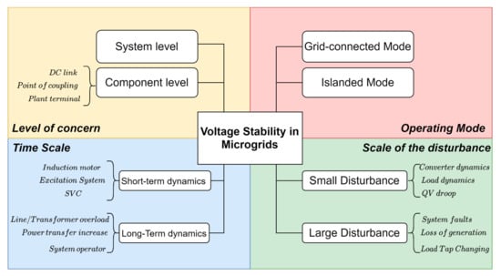
Figure 1.
Voltage stability classification in microgrids.
The classification diagram shown in Figure 1 starts from the operation state of the microgrids and expresses several common factors influencing voltage stability. Among these, tap changers are the main sources of voltage stability problems in utility microgrids [9]. Voltage stability in remote microgrids is related to reactive power compensation in the network. The voltage stability problem in facility microgrids mainly comes from the type and quantity of micro power supply and under-voltage load shedding. Various disturbances can be classified in terms of the disturbance size and duration, resulting in different voltage stability issues in microgrids. Large disturbances affect the entire system’s stability for long durations and can cause problems including line faults and generation loss. Voltage fluctuations due to significant disturbances reflect the ability of microgrids to regulate bus and feeder voltages, which requires the nonlinear characteristics of the power system components to be considered. Small disturbances are related to minor changes in the system, such as load changes. For voltage stability problems resulting from minor disturbances, such as load increment changes and other minor changes, a linear approximation of the power system components can be used in the analysis.
Voltage stability analyses can be divided into two main categories: analytical methods and optimization strategies. Static and dynamic analyses constitute two branches of voltage stability analysis. The uniqueness of static voltage stability analyses was shown by [12,13] through comparative simulation experiments using the Jacobian method, voltage sensitivity method, active and reactive loss sensitivity method, and energy function method. A previous study [14] involved a DC microgrid with ZIP load connected. Such loads have the ability to adjust the proportional power and bus voltage weighting value simultaneously. This article uses the Laplace matrix in the stability analysis of the system.
The dynamic voltage stability analysis methods have not been clearly classified, unlike the static voltage stability analysis methods. A previous study [15] researched the relationship between steady-state behavior and a dynamic model of a power system. Another study [16] presented a dynamic analysis of different PV penetration effects on a power network. In [17], the effects of thermostatically controlled loads on the dynamic voltage stability of a power system were investigated based on the small disturbance method. Several voltage stability improvement strategies have been reported in the related body of literature. The main strategies for voltage stability improvement include reactive compensation, load shedding, modified current limiters of micro-sources, and voltage regulations with DGs. In [18], the isolated longitudinal system was improved by applying different reactive compensation options. For the load-shedding-related strategy, [19,20] demonstrated the effects of various undervoltage load shedding settings on the motor load, and the stability improvement was shown via simulation. In [14,21,22,23,24,25], the optimal arrangement strategies for DGs and the related voltage regulation schemes are presented. The stability characteristics of load dynamics and reactive power compensation were analyzed in [26,27]. An arrangement method for the current components was proposed to enhance the modification of the current limiters’ dynamic voltage stability in [28,29,30]. In [31,32], an optimized reactive power compensation strategy was proposed.
The purpose of this article is to determine and discuss the voltage stability analysis methods designed for renewable-dominated power systems. In particular, we focus on the islanded microgrid, which has not been treated in detail in previous review papers. In addition, the voltage stability indices applied in microgrids are systematically analyzed, compared, and reviewed based on their different DG types. Specifically, the paper aims to
- Investigate the analysis and verification of voltage stability studies based on different renewable energy generation types;
- Classify and compare voltage stability analysis methods based on different microgrid operation modes and types of DGs; and
- Evaluate voltage stability techniques and conduct a simulation verification to demonstrate the most suitable simulation platform with different microgrid settings.
The state-of-the-art voltage stability analysis methods applied in renewable-dominated power systems are presented in detail in this paper. This paper takes the form of five sections, including this introductory section. The classification and the mathematical models related to voltage stability analysis methods in terms of both static and dynamic analysis are presented in Section 2. The voltage stability index (VSI) models proposed by researchers in recent years are classified and compared in Section 3. Section 4 presents a comparative discussion of simulation tools and techniques that can be used to verify and apply voltage stability methods to simulations and experimental case studies. Section 5 concludes with the implications of the development with respect to future research recommendations on voltage stability analyses in renewable-dominated power systems.
2. Voltage Stability Methods of Analysis
The significance of voltage stability analyses is the determination of vulnerable parts of microgrids through appropriate evaluation methods. Improving voltage stability can identify reasonable solutions for further optimization, enhance the system’s strength, and enhance the tolerance level of abnormal operation of the microgrids. The continuous replacement of synchronous generators by inverter-based units puts a limit on the reactive power capacity of the system, leading to an unstable voltage after the occurrence of external interference [33,34]. The voltage stability analysis method can be selected based on the microgrid stability mechanism [35]. Reactive power Q and bus voltage V are direct measurement parameters of voltage stability for microgrid systems. When the V–Q sensitivity of all buses in the system is positive, the voltage of the power system is stable. If at least one current V–Q response is negative, the voltage of the power system is unstable.
Figure 2 shows the classifications of voltage stability analysis methods, including static and dynamic voltage stability analyses. Static analysis techniques analyze the voltage stability by using the static operating parameters of microgrids to determine the key factors affecting the stability. Static analysis techniques only consider the static operation of microgrid systems, and the real-time variable differential equation is set to zero. At present, static analysis techniques are commonly based on load flow analyses, such as P–V, V–Q analysis, and V–Q sensitivity analysis [36]. Dynamic voltage stability analysis methods are helpful when analyzing voltage collapse and testing the application effect of the control strategy. Dynamic analysis methods are similar to transient analyses of the power system, where a set of differential equations is used for system modeling. As the dynamic influence on the system’s stability usually changes relatively slowly, the system’s static operating parameters are still used in most dynamic voltage stability studies.

Figure 2.
Classification of voltage stability analysis techniques.
2.1. Static Voltage Analysis Techniques
At present, a series of the existing static voltage stability analysis methods of microgrids is based on the calculation and modification of the load flow equation. The microgrids are modeled by the following first-order differential equations [36]:
where is the state vector, is the bus voltage vector, and is the admittance matrix of bus N.
In static analysis methods, when the value of is zero, the system operates under steady-state conditions and represents the margin of stability. In load flow equations, a feasible solution is based on the judgement of system voltage stability, which means that the feasible solution to the load flow equation is the voltage stability limit of the microgrid. In addition, static voltage stability analysis methods can provide researchers with information on the system voltage stability margin and state variable sensitivity. Consequently, static voltage analysis methods for microgrids are generally divided into three categories: the load flow method, the modal analysis of the Jacobian matrix, and the singular value decomposition method. Several common static voltage analysis techniques are summarized below.
2.1.1. Continuation Load Flow Method Using P–V and V–Q Curves
By constantly updating the load flow equation and calculating the existence of a solution to the load flow equation, the convergence problem near the stable operation limit point can be solved, and the voltage stability limit can also be obtained. Moreover, the approximate voltage collapse point is rounded by the continuous prediction and correction process. This solution is the continuation load flow method based on the convergent solution to the load flow calculation. A set of load flow results are obtained by changing the load value P or Q of the selected bus and operating the microgrids with all other parameter settings unchanged. When the load flow algorithm cannot converge, the corresponding point is the voltage collapse point, which is the margin of the stable and unstable states of the microgrid. Figure 3 shows P–V and V–Q curves illustrating the voltage characteristics in terms of both active power and reactive power [9].
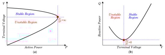
Figure 3.
(a) P–V and (b) V–Q curves obtained for the voltage stability analysis of a power system showing stable and unstable regions.
As one of the conventional methods, the continuation load flow method has been studied for a long time. It has been used extensively to calculate the critical voltage collapse point, helping to determine the voltage stability limit. However, this method is only suitable for simple microgrid systems and cannot be applied to large and complex systems, as the calculations are highly time consuming.
2.1.2. Modal Analysis of the Jacobian Matrix Based on V–Q Sensitivity
In the modal analysis method, the sensitivity matrix is obtained by linearizing the load flow equation of the system [37]:
where is the bus real power change, is the bus reactive power change, ∆ is the bus voltage angle change, is the bus voltage magnitude change, and is the Jacobian matrix.
By assuming that the real power is constant in the calculation (due to the static nature of the analysis), the sensitivity matrix equation is inversed to obtain the following equations [35]:
In the equations above, is the V–Q sensitivity matrix. Specifically, if the value of is positive, the system voltage is stable. If not, the system may be an unstable system.
In [38], a new and time-saving sensitivity-based voltage stability analysis method was proposed. This method deduces the Thevenin-Based Voltage Stability Margin based on the amplitude and angle of the node voltage for preventive control. Unlike other commonly used sensitivity methods, this method does not need complex calculations to consider the maximum loading point (MLP) in real-time applications. In the simulation results, the accuracy and rapidity of this method are successfully verified for power systems without emergencies. However, this method is unsuitable for systems with emergencies, allowing room for improvement.
In [39], a method for validating the sensitivity of the voltage stability margin was proposed. This method can be used to identify the weakest voltage stability bus and the node-set. This research extends the application of such a method to a multi-machine system from a Single Machine Infinite Bus (SMIB) system.
In addition, the standard P–V curve or V–Q curve method has been applied by many studies in the literature. In [40], Bonneville Power Administration power analysis platform (PSD-BPA software) was used to apply this method to a wind-power generation system. In [41], Dlgsilent PowerFactory was used to analyze the impact of large-scale wind power on the state grid. PowerFactory was also used in [30] to analyze a power system with photovoltaic power generation. In [42], the influence of new energy generation on power system stability was studied by using continuation load flow (CPF) combined with a P–V curve analysis in the PSAT power system toolbox environment. The sensitivity modal analysis method is simple and easy to apply. It only needs a small amount of computing and is therefore more efficient for data processing. However, this method is not suitable for microgrids with complex network configurations because of the weak linear characteristic of the index.
2.1.3. Singular Value Decomposition Using Network-Load Admittance Ratio
If the load condition of microgrids is close to the critical state, the trend of the Jacobian matrix can be close to singularity. Therefore, the singular point of the Jacobian matrix of the load flow equation can represent the critical point of system voltage stability (voltage collapse point). In addition, this method plays a crucial role in static voltage stability analysis methods.
Y. Song et al. [43] proposed an index representing the load admittance ratio based on the improved load flow Jacobian matrix for the voltage stability analysis of microgrids. In their paper, a simple two-bus system was used, as shown in Figure 4. The method was applied to a network with distributed generator systems (DGS) that could be simplified by equivalent admittances of the load and transmission lines. The ratio-based function presented in the literature is expressed as
where approaches infinity when there is no load, and is the voltage stability limit point. As a result, the voltage stability index ranges from 0 to 1 (stability limit point to no load). Refer to [44] for the detailed linear index calculation.

Figure 4.
A typical two-bus system for load and transmission line equivalent admittance method.
The voltage stability analysis index is determined according to the parameters of the power grid, load, and distributed generation. This concept is a generalization of the line load admittance ratio, representing the load state of the general distribution system considering the influences of constant-power distributed generators (CP-DGS) and constant-current distributed generators (CC-DGS), as illustrated in Figure 5. The admittance ratio represents the load state of the distribution system and considers the influence of distributed generation. It has been proven that the Jacobian load flow is singular when the network load admittance ratio is 1. Additionally, the Voltage Stability Index (VSI) has been verified on several IEEE test feeders. Simulation results have shown an excellent linear relationship between the network load admittance ratio and the load growth, and the voltage stability margin can be well estimated. In addition, the index reflects the influences of the DG access level and control mode on voltage stability.
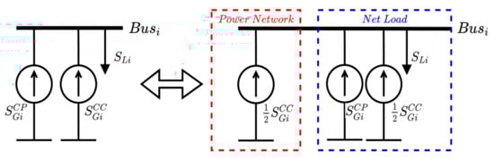
Figure 5.
Illustration of CP-DGS and CC-DGS equivalents.
In [45], a voltage stability analysis technique was proposed based on the smallest eigenvalues and the associated eigenvectors of a reduced Jacobian matrix. The eigenvalue modules describe the voltage stability of the current state. This work is based on an early scheme of the singular value decomposition method, which has been improved and applied many times.
In summary, a singular value decomposition method based on the linearized load flow equation was proposed. Because of the high nonlinearity of the Jacobian matrix, this method cannot accurately analyze the voltage stability.
2.1.4. Transfer Capability Evaluation Using Static Analysis Methods
The overwhelming cost of power transmission network development and the need for improved transfer capability has raised significant concerns regarding distributed energy system planning [46,47]. Therefore, several correlational studies are being conducted to investigate the impact of voltage stability on the power transfer capability. The advantage of considering static voltage stability analysis is that both bus voltage and its voltage stability limits can be fully considered during the calculation. In [48], a static Thevenin equivalent method to estimate the voltage collapse point and the system stability margin with wind generation was proposed. This study evaluated the assessment methods at a wind hub connected to a medium-voltage transmission network. The wind hub was modeled using the Thevenin equivalent parameters to calculate the maximum power transfer capacity, and the simulation results show that the power transfer capability can be seen as a linear relationship with the voltage stability. In [49], the power transfer capability was studied based on the continuation load flow analysis. The maximum loading factor can be calculated through continuation load flow analysis, and the power transfer capability limit can be obtained with a simulation. Although this method is effective and intuitive, it is unlikely to produce a global optimum, as the calculated loading factor presents a system-wide limit and finding the optimal settings for bus connections is challenging. In addition, only the voltage limit and line thermal limit can be considered when determining the power transfer capability, while other practical factors are neglected (e.g., the uncertain regional weather of the transmission network, which is important but not considered in the continuation power flow methods).
2.2. Dynamic Voltage Analysis Techniques
Static voltage stability analysis methods have been widely employed in voltage stability analysis cases. However, given that power systems are dynamic entities and voltage instability and collapse are also dynamic responses, the analysis of dynamic voltage stability is also of particular importance [50]. Dynamic voltage stability analysis is critical when investigating the long-term impacts of high time-varying components in microgrids. Dynamic voltage stability is the ability of the power system to maintain a balance between load demand and supply [51,52]. Compared to static analysis methods, dynamic analysis methods can reflect the behavior of system components in a more practical manner.
The time-domain simulation method is the most suitable method for dynamic voltage stability analyses and is suitable for any power-system model. Different load models will lead to different conclusions by building different time-domain simulation dynamic models. In [53], a generalized load flow calculation model was proposed to simulate the behavior of a distributed generation system. In that study, a set of time-domain nonlinear equations was used to represent an islanded microgrid, and the V–Q sensitivity was analyzed. In [54], a voltage analysis index based on network loss sensitivity, which is used for online simulation and tests, is discussed. Although this method has broad application, there is still dispute over its use because of its different simulation characteristics for different load models; thus, it needs to be further optimized and studied. Short- and long-term voltage stability evaluations can be carried out through time-domain dynamic simulation of the microgrid system represented by differential-algebraic equations (refer to Equation (12)). The differential equations in the transient response can be solved by using numerical integration techniques. Several dynamic voltage analysis techniques are reviewed below.
2.2.1. Small Signal Analysis Method
The small signal analysis method is applicable for minor disturbances. It is based on the linear differential equation of the distributed networks. It is suitable for determining the voltage stability influence of on-load tap-changing transformers, dynamic loads, and generators. By modeling the differential-algebraic equations, the system is linearized at the balance point, as shown below:
where is the system state variable, and is the algebraic variable.
When the algebraic variation is zero, the linearized system can be expressed as
where is the coefficient matrix of . To this end, the voltage stability of the small disturbance system can be estimated by calculating the eigenvalue of matrix J.
The Jacobian matrix presented in Equation (3) retains the Q–V relationship in the power system and expresses the linearized steady-state voltage equation in the static analysis. The modal analysis of the Jacobian matrix is usually used in static voltage stability analyses. Even though the small signal analysis method used in dynamic analyses is based on the modal analysis of the Jacobian matrix, there are still some differences between the modal analysis used in the static analysis and the small-signal-based dynamic analysis.
The first difference is the computational complexity. Dynamic analyses study the transient stability of the system, including the influences of the dynamic loads and generators, whereas static analyses focus on the solutions to algebraic equations of the system’s state. Applying the small-signal analysis in dynamic studies can be more complex. However, the application of the modal analysis to static analyses mainly focuses on how far the stability margins move away from the voltage stability collapse point, a process that is computationally less extensive.
Secondly, dynamic analyses represent a kind of hybrid evaluation tool composed of the static analysis method and nonlinear analysis tools and are based on the use of fundamental modal analysis in static analysis methods. Small-signal voltage stability analyses usually involve the use of static analysis tools, such as the modal analysis of the Jacobian matrix and the power flow analysis. However, the small-signal-based dynamic voltage stability analysis method is a combination of linear and nonlinear analysis tools.
In [55], a reduced-order small-signal-analysis model was proposed for an islanded microgrid with multiple micro sources. The eigenvalues were obtained with the system matrix by linearizing around the operation point. The simulation results were compared and verified with the PSCAD platform.
The bifurcation method is also a critical theory that is used to analyze the voltage stability for small signals. Bifurcation refers to a phenomenon that leads to a sudden system stability change when one or more parameters in the system change. The changed parameter value is called the bifurcation value. There are two main bifurcation structures in the mathematical representation of power systems: Hopf bifurcation and saddle-node bifurcation. Hopf bifurcation refers to the phenomenon where a pair of complex conjugate eigenvalues are on the imaginary axis, resulting a loss of stability and continuous oscillation in the power system. Saddle node bifurcation is a process in which a real eigenvalue is located on the imaginary axis, and the system completely loses stability with the continuation of bifurcation. Local bifurcation theories, such as P–V and P–Q curves, can be used to determine the characteristics of static parameters when bifurcation occurs. Bifurcation theory is an essential aspect of studying the dynamic stability of the power system. In [45], the Hopf bifurcation-related method for the system was developed. The authors of [56] used the bifurcation theory analysis on an AC islanded microgrid under loop control and detected Hopf bifurcation and the saddle-node bifurcation points in the power system. Furthermore, they predicted the unstable bifurcation margin, thereby increasing the computation efficiency for the voltage stability analysis and prediction.
2.2.2. Large Signal Analysis Method
Voltage stability analyses are generally restricted to small disturbance studies, where the system has voltage instability issues due to slow changes in system parameters. However, researchers have found that transient phenomena, such as tripping incidents, short circuits, and blackouts, can lead to significant load voltage changes that cannot be kept constant [57]. In this context, large-signal voltage stability analysis methods play an important role.
The Lyapunov-based method is a large-signal voltage stability analysis method based on the dynamic performance of switched microgrid models. It is used to develop solutions to differential equations. If the switched system’s state transition matrix has negative real eigenvalues, the system tends to stabilize [58]. The Lyapunov equation is shown below:
where P and Q are symmetric matrices.
A positive Q and a unique positive P exist for a switched linear system that can satisfy the Lyapunov equation [9]. In [59], a model consisting of nonlinear elements for the microgrid, including the loads and generators, was developed. Based on the Lyapunov stability theory for a closed-loop system, all eigenvalues in the Jacobian matrix should have negative real numbers. The research results prove that the dynamic voltage stability scheme could work well for the microgrid system. In [60], an energy-function-based voltage stability analysis method for the islanded microgrid was developed. The energy function method directly uses the Lyapunov theory to analyze the system’s voltage stability. The whole model is divided into two parts: the energy function and the auxiliary function. The energy function considers the change in load, the solar radiation, and the energy storage system charging conditions, allowing direct evaluation of the stability of the system’s operating point. The energy function expression is [61]:
where is the measured value that indicates the system’s energy balance, n is the system’s node number, and f and g are the power values.
The researchers simplified the load model as a static model instead of using a dynamic model, so the dynamic characteristics of the load were not considered. The simulation results of the IEEE 37-bus test feeder show that the energy function is effective for voltage stability evaluation. Auxiliary function technology can improve the stability of the system when the intermittent power supply is configured in the microgrid area. The closer the energy measure value is to zero, the lower the voltage stability is. The method based on the energy function does not completely suffice for predicting load characteristics. Thus, the efficiency of this method remains to be proven. However, it presents an idea for combining static voltage stability and dynamic analyses.
3. Voltage Stability Analysis Indices
The voltage stability analysis techniques mentioned in Section 2 can be used to evaluate the voltage stability of microgrids. Nevertheless, such techniques cannot indicate how far the system is from the voltage collapse margin (i.e., the boundary between system voltage stability and instability). Therefore, the concept of the voltage stability index (VSI), through which the level of system stability can be obtained, was introduced. This allows a comprehensive voltage stability analysis to be performed based on the inclusion of one or more voltage stability indices. To understand the voltage collapse proximity of the microgrid system more accurately, as well as the maximum load capacity of the system, and to identify the bus with the weakest stability, the use of the voltage stability index is essential. The voltage stability index, however, has a high calculation cost when quantifying stability. This section reviews the use of the voltage stability index in the current research field.
3.1. VSI Classification
This section systematically classifies the VSI and reviews the related methods according to different classifications to understand how the voltage stability analysis index is applied to microgrids. At present, there are many directions for VSI classification in the research field, among which the most common method is classification according to the variables used in the VSI definition formula. For example, in [36], VSIs are divided into the index class, eigenvalue decomposition class, and line data class based on system variables and the Jacobian matrix. In [62], the authors classified the indices as the Jacobian matrix index and system variable index according to the formulation mechanism. In addition, these indices can be classified according to the evaluation target, for example, according to the measurement target and the voltage instability mechanism. As per the voltage instability classification presented in [46,47], the areas that are most prone to voltage collapse in the power system can be identified through different VSIs. In [63] classification according to offline or online VSI applications was proposed, in which offline is suggested for VSI applications of buses and online is suggested for VSI applications of lines. Figure 6 shows the VSI classification framework, including the mentioned categories.
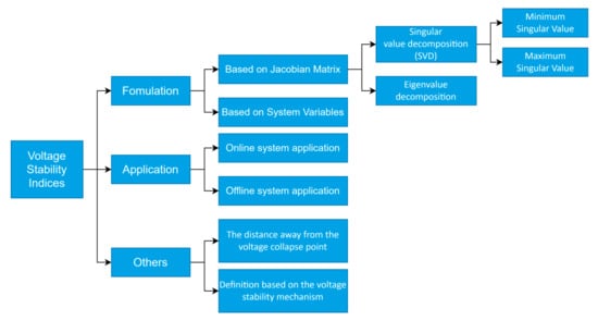
Figure 6.
Voltage stability indices classification.
3.2. Voltage Stability Indices Review
Researchers have compared, analyzed, and classified the voltage stability indices from different aspects [64]. At present, the most commonly used VSI classification scheme involves dividing VSIs into two categories based on the Jacobian matrix and system variables according to the VSI formula [65]. In addition, in [66,67,68], several common indicators are compared and classified based on load shedding and optimal storage in critical cases. This section reviews and analyzes the microgrid-based voltage stability indices proposed in the literature.
3.2.1. Jacobian-Matrix-Based VSIs
A VSI calculation based on the Jacobian matrix needs all of the system’s data. Its central theory involves singular values and the eigenvalue index. Based on the singularity of load flow, the Jacobian matrix is close to singular at the point of voltage collapse. It requires a significant amount of calculation and detailed power system information.
In [69], a singular value decomposition (SVD) method was developed, and the following equations illustrate the detailed formulation of this technique:
where is the singular value, is the left singular vector, is the right singular vector, is the singular vector, , , are the values of the matrix from the ith column, provides details about the critical bus, and shows the power mismatch details for .
Here, the vectors and provide information on the weakest bus and area of the power system, respectively. The minimum value of illustrates which bus is the weakest.
Singular value decomposition has been demonstrated to be a superior method for voltage stability analysis in comparison to modal analysis in the following aspects: the SVD method only has one mode in comparison with the modal analysis, which has several modes. It is hard to determine the weakest operating mode in the modal analysis. The SVD method uses the full Jacobian matrix instead of the reduced Jacobian matrix, which is used in the modal analysis. Even though the complexity of the question is reduced in the modal analysis, the P–V and Q– coupling issues cannot be focused on under the reduced matrix method. The SVD method is used to identify the weakest boundaries during voltage stability analysis, which is helpful when conducting the correction analysis in further steps.
In [35], the basic formulation and definition of the eigenvalue decomposition technique are shown. The following equations illustrate the detailed formulation used in this technique.
where is the right eigenvector of matrix , is the left eigenvector of matrix , is the diagonal eigenvalue matrix of , v is equal to , q is equal to , and is the ith mode of the V–Q response. If is positive, the ith voltage and modal reactive power are directly proportional, and the system is stable. If is negative, the ith voltage and modal reactive power are not directly proportional, and the system is unstable.
In [70], the sensitivity of the steady-state power system model was analyzed based on the theorem that the Jacobian matrix J is a singular matrix at the critical point. Through the parameterization of the load flow equation and the correlation operation of the left eigenvector after Taylor’s expansion, the approximate expression of the sensitivity matrix of the power system with new energy generation can be obtained [71,72]:
where is the node power random disturbance coefficient, is the loading margin, and r is the node number.
The sensitivity matrix expresses the influence of the load margin on the power random disturbance coefficient. Combining the VSI calculation method with the cumulant-based maximum entropy method (CMEM) in probability theory, the randomness of wind power, PV, and other types of renewable energy power generation and the impact of power load consumption on the load margin can be measured. Compared with the series expansion method, this method has greater sensitivity under different levels of renewable energy permeability, leading to more accurate and effective analysis results. As this method considers the probability theory principle of accumulation and an increase in maximum entropy, it takes into account the correlation and uncertainty of power injection and consumption. Therefore, this method is more suitable for renewable energy power generation systems. Additionally, compared with the Monte Carlo method (MCM), this method has a higher calculation speed. Comparative experimental results show that this method is up to 99.95% quicker than the MCM method. This is because the CMEM method can classify samples through K-means clustering technology, which significantly reduces the redundancy of repeated operations. Therefore, the scheme is suitable for microgrid systems with integrated renewable energy generators.
3.2.2. System-Variable-Based VSIs
In [73], a new stability index based on a two-bus equivalent circuit (SMIB system) was developed, as shown in Figure 7a. By simplifying the equations, the above basic index was developed in the presence of tap changers and DGs based on Figure 7b. The proposed index was obtained using the following equations:
where t is the transformer ratio.

Figure 7.
(a) Two-bus system; (b) equivalent circuit after removal of the transformer (elements transferred from the primary side to the secondary side) in the presence of tap chargers and DGs.
Based on this improved VSI, researchers can easily detect the voltage stability level in the system with distributed generators. This method can be used to rank the voltage stability of the network bus through the calculation of VSI, and then the weakest bus can be identified. Unlike using the Jacobian matrix to obtain the stability index, the VSI calculation method does not calculate the Jacobian matrix and bus impedance matrix of the whole system. Instead, it directly uses the power value of the system from load flow calculations, and therefore the problems of low calculation speed and complex calculation are avoided to a great extent. Thus, this method has the advantages of involving simple calculation and high accuracy, which makes this index suitable for the study of the voltage stability of distribution networks with a large number of buses. In addition, this method is suitable for microgrids with tap changers. However, many system parameters, such as R, X, P, Q, the Jacobian matrix and the admittance matrix, are not considered in the calculation. Although this method improves the calculation efficiency, it ignores the influences of these parameters on the system.
In [74], a novel VSI, named the fast voltage stability index (FVSI), was proposed to identify weak voltage stability areas or buses. In this method, for base load to peak line loading situations, each bus is evaluated by the FVSI to check if it is the weakest one in the whole system. If the FVSI is equal to one, the system is unstable. The lower the FVSI, the more stable the bus voltage is. The line index is calculated using the following equation:
where is the line impedance, is the line reactance, is the sending end voltage, and is the receiving end reactive power.
In [75], a quantitative transient voltage evaluation index based on the ultrahigh-voltage direct-current (UHVDC) transmission terminal that can analyze and determine the dynamic reactive power compensation capacity was proposed. With the high proliferation of renewable energy generation, several UHVDC projects have been designed to transmit renewable power from remote areas to the capital cities, which have great demands for electricity. Thus, research on voltage stability analyses for the UHVDC transmission system is also worthwhile. The voltage stability in each region is quantitatively compared using the approximate step function, absolute sensitivity, and relative sensitivity. The voltage stability index proposed in this paper is suitable for power systems with a UHVDC transmission system. It is used to evaluate the transient overvoltage state of the UHV transmitting power system. Here, the concepts of absolute sensitivity and relative sensitivity are proposed. The parameters of this method are set according to the operational requirements of the UHVDC transmission system rather than those of the distribution network. Therefore, this method is more suitable for actual large-scale networks in the selection of parameters. However, the analysis parameters proposed in this paper are based on a DC transmission system, so this scheme is not suitable for AC microgrids, which means that the application scenario of this scheme is relatively limited.
In [76], a voltage stability index based on sensitivity factors that consider the power system load was proposed. The formula was defined as below:
where and are diversity and scale factors, is the Lagrange multiplier for bus I, and is the loadability for the current operating state.
The VSI index (d-index) shown above can indicate the stability state of the system with a range of 0 to 1 (stable to unstable). Using ZIP and the exponential model and considering the difference between the maximum power transmission point and load point, the voltage stability of different bus loads under different stress conditions can be evaluated. The index was improved by using the traditional L-index stability analysis method. The scheme uses the concept of the Lagrange multiplier. Previous experimental results show that with an increase in the load to voltage collapse, the Lagrange multiplier related to maximum reactive power generation will decrease when the power system approaches the maximum load limit. Therefore, one advantage of this scheme is that it can refine the exponential response through multiple attempts to change the parameters. Compared with other similar VSIs, the d-index performs better. The L-index presented by P. Kessel, and H. Glavitsch [77] is the traditional method and can conservatively evaluate the steady-state of the system. However, when the L-index reaches the MPPT limit, this will cause a false alarm for the system state, leading to erroneous results. As the exponential response of the d-index is refined according to different parameters in different systems, it can better estimate the proximity of voltage collapse than the traditional L-index method.
To effectively present how voltage stability analysis can be employed in renewable-dominant power systems, a summary of the stability analysis methods, VSI, analytical foundation, equation, and the stability threshold is presented in Table 1.

Table 1.
Summary of voltage stability analysis methods and applications.
4. Verification Case Studies for the Voltage Stability Analysis
4.1. Analysis and Verification Case Studies with Integrated PV Generation Only
In [99], based on the Monte Carlo simulation and traditional voltage stability analysis methods, including the model analysis and V–Q curve model, a model framework for analysis was proposed. The aim was to improve the understanding of the relationship between photovoltaic energy penetration and power grid voltage stability. The critical eigenvalue, line loss, and reactive power were considered in the stability analysis. By changing the photovoltaic energy penetration in the IEEE 14-bus test system for model simulation and verification, the impacts of different photovoltaic energy penetration levels on the power grid voltage stability were analyzed. In [100], it was shown that photovoltaic power generation can easily lead to short-term voltage instability for a low-voltage distribution network. In [101], it was shown that with an increase in photovoltaic permeability, the intermittence of power generation will have a more significant impact on voltage fluctuations in the power grid. Therefore, starting from the existing photovoltaic power generation system, this study analyzed the voltage stability of different permeabilities using a new test model. We analyzed the voltage stability of a standard IEEE 14-bus system with five synchronous generators and three synchronous compensators. Through the V–Q curve analysis method, the reactive power margin of each bus was calculated and measured. Bus 14 was the most unstable bus with the lowest reactive power margin and the highest bus participation coefficient. On the contrary, bus 4 was the most stable. After identifying the weakest and strongest nodes in the system through the V–Q curve method, the researchers converted all constant power loads into random loads and integrated the photovoltaic power generation system at the weakest bus. Through a sampling test of statistical data, the impacts of PV penetration on the overall system under different loads in different periods were obtained. The new framework presented in this paper can be used to evaluate the voltage stability of embedded photovoltaic systems. The novelty of this scheme is that it combines the traditional voltage curve method and the Monte Carlo simulation evaluation method to simulate uncertainty between photovoltaic energy and the system load.
In [102], a parametric model of effective reactive power (E-VAR) for evaluating the voltage stability of power systems with large-scale photovoltaic power generation is proposed. The high penetration of photovoltaic power generation reduces the flexibility of traditional power-system development. Moreover, due to the lack of E-VAR in the power grid, power system networks containing large-scale renewable energy are vulnerable to faults, affecting delayed voltage recovery. Therefore, using E-VAR as the research goal, several VAR resource contributions and load bus voltage recovery indices were quantified and a recovery index was designed. The New England power system (IEEE 39-bus) was tested with a simulation on the DIgSILENT power factory platform. The scheme is mainly applicable to power systems with single pieces of large-scale new energy generation equipment. The simulation results prove that the VSI can efficiently analyze the impact of large-scale new energy on a system’s transient stability. Furthermore, the optimal new energy integration location was obtained through the simulation analysis and can be used to help transmission system operators introduce more new energy generation resources without affecting the system’s stability.
In [81], the dynamic voltage stability of a power system with large-scale photovoltaic power generation was studied. This method is different from the static voltage stability verification models mentioned above. This study examined the system’s response to interference, identified the dynamic voltage characteristics, and determined the optimal location and scale of grid-connected new energy power generation according to the dynamic voltage stability analysis. Based on the investigation of the fault contribution of inverters, this analysis method forms a comprehensive framework that can be used to evaluate dynamic voltage characteristics. It was verified on the New England IEEE 39-bus test system using the DIgSILENT platform. Furthermore, by analyzing the SGs Var capability and the Var flow in the power system, the effects of different load conditions and PV penetration levels on the system’s transient response were studied. The biggest highlight of this scheme is the realization of a dynamic voltage stability analysis on a system with large-scale photovoltaic power generation. In [99], a static voltage stability analysis model for photovoltaic power generation was proposed. This study used the traditional P–V and V–Q curves and the PowerWorld simulator for their analysis. The effects of variable power factor control, static voltage stability, generation power, and the threshold voltage distribution of photovoltaic power stations were studied. The change in voltage power sensitivity was used to optimize the configuration position of photovoltaic power generation to optimize the static voltage stability of the whole system. This method is a verification test of the traditional curve analysis method that uses different software platforms to those used by other methods. The advantages and differences of several different simulation platforms can be obtained through comparison.
In [103], a dynamic voltage stability analysis evaluation frame was proposed for power systems with a high load capacity and a large-scale PV system. The model checks the power system’s response to internal and external disturbances, understands the dynamic voltage characteristics, and determines the optimal location and scale of grid-connected renewable power generation units based on inverter resources. The dynamic voltage characteristic analysis framework uses the photovoltaic penetration level, load size, dynamic load percentage, and fault location to understand the system’s dynamic voltage characteristics under different operating conditions. Using the DIgSILENT software platform, the proposed dynamic voltage stability analysis framework was applied to the IEEE 39-bus test system. The test results quantified the indicators of load bus voltage recovery to explore the steady state, transient response and voltage trajectory of the system.
In [104], the impact of the PV system on islanded microgrid static voltage stability analysis was researched. This study used the voltage collapse proximity index of the maximum deliverable power to conduct a quantitative stability analysis. The traditional P–V curve method was improved and verified using an improved IEEE standard 15-bus test model [105]. In addition, five different scenarios were applied to verify the system’s ability to maintain the voltage stability. Using the coupling circuit breaker between buses to change the exchange power, the improved P–V curve method was used to evaluate the impact of PV access on the system’s voltage stability. In addition, the researchers considered different working conditions such as varying photovoltaic penetration levels, the impact of the PV power factor, and the impacts of different PV model units on the stability simulation.
In [106], a transient stability analysis and voltage stability compensation system based on reactive load flow control were proposed. This method was shown to provide increased power demand and improve stability. The authors connected photovoltaic power generation to the power grid in MATLAB Simulink to conduct stability studies. Three different fault types were applied, including single line to ground (LG), double line to ground (LLG), and three-phase line to ground (LLLG) faults. The transient stability analysis results were compared based on different photovoltaic power generation connection types. It was concluded that the rational use of photovoltaic power generation can effectively improve the stability of the power system.
4.2. Analysis and Verification Case Studies with Integrated Wind Generation Only
Hemmatpour et al. [60] developed a saddle-node and limited induced bifurcation-based voltage analysis model in which the wind turbine generator is considered in a microgrid. The index is based on the saddle-node and finite induced bifurcation, and the authors considered different load models. A new voltage stability margin of the islanded microgrid, called cat_VSI, was defined by catastrophe theory: the larger the index, the more stable the system is. In addition, a new concept called the reduced islanded microgrid network was proposed. The proposed index was extended to the N-bus islanded microgrid by splitting the network. This method is called the maximum load margin of islanded microgrids. In the simulation, the performance and effectiveness of the proposed method were verified on 33 buses and 69 bus test systems with different load models. In this simulation model, both the wind turbine and the frequency deviation issues were researched. Two types were presented for the voltage stability index: saddle-node bifurcation (SNB) and limited induced bifurcation (LIB). The simulation process showed that the simplified static voltage stability analysis method proposed in this paper is comprehensive and detailed. Furthermore, the method was verified by simulating different test feeders with a wind turbine, showing that the voltage stability analysis model has very strong robustness and high generalization ability for wind-turbine-based islanded microgrids.
In [61], a method for short-term voltage stability analysis after the occurrence of a fault was proposed. This method is a system-level method for the quantitative analysis of voltage stability. In this method, the concept of integral estimation equivalent to the stability of the input state is used for quantitative analysis at the subsystem level. The authors studied the short-term voltage stability at the subsystem and system levels through a time-domain simulation, quantified the disturbance that the system can withstand, and provided a method for quickly conducting a system-level voltage stability analysis.
In [5], a voltage stability evaluation of power systems with wind power penetration was conducted. In this study, the P–V curve was used to determine the voltage stability limit of the system. DIgSILENT PowerFactory software was used for the simulation, and the results were analyzed with MATLAB. The verification results show that changing the settings of the controllable series capacitor can change the circuit of the power grid, improving the voltage stability limit and ensuring the steady-state operation of the power system with an increase in wind energy penetration.
In [60], the influence of wind turbines connected to the power system on the static voltage stability was studied. Using the traditional P–V curve method, the static voltage stability of wind power incorporated into the traditional power grid was analyzed using psd-bpa software. The experimental results show that the influence of wind power on power grid voltage stability is closely related to the DG capacity. Although wind power grid connection will increase the load power limitation, it will reduce the voltage threshold. Therefore, when the system has enough reactive power, the wind power grid can improve the static voltage stability of the system. Combined with the existing Zhanjiang City power system, this paper studied the static voltage stability of the wind-power-connected grid.
The increase in wind energy in low voltage ride through or drop periods leads to power system instability and voltage quality problems. In [78], a microgrid with wind power generation was applied to various scenarios and simulated using Dlgsilent PowerFactory and MATLAB/Simulink. The voltage sag behavior and active and reactive power behaviors in the simulation models of the two platforms with and without capacitance were analyzed. The results show that combining a supercapacitor into a doubly fed wind power generation system can improve the voltage stability of the microgrid and provide a high-quality and stable power supply.
In [84], a voltage stability index for evaluating the grid connection effect of wind farms with doubly fed induction generators was proposed. The index based on impedance was improved by using the voltage stability constrained optimal load flow calculation. Furthermore, a voltage stability analysis index considering the limit of the DFIG capacity curve and on-load tap changer behavior was proposed. In this study, simulation verification was carried out on the improved WSCC test system, the IEEE 39-bus system, the IEEE 57-bus system, and the Poland 2746 bus system. The experimental results show that this method can be used to analyze the instability behavior of a power system with a doubly fed induction turbine system.
In [85], a method for evaluating the voltage stability of a power generation system containing wind energy was developed. This method adopts the optimal load flow algorithm. By determining the Hessian matrix of the power balance equation, the minimum singular value of the system Jacobian matrix can be associated with the change in the actual power injection of the bus to evaluate the system’s voltage stability. The method was applied to the IEEE 6-node, IEEE 57-node, and IEEE 118-node systems with wind-power generation. This study compared the minimum singular value method of the Jacobian matrix with a proposed optimized method via simulations and proved that the two schemes can effectively be used to analyze the voltage stability of a wind turbine system.
In [96], a new voltage stability constrained wind energy planning (VSC-WEP) model was proposed. The model is suitable for determining the optimal wind power penetration into a system based on the voltage stability. In this model, the modal analysis method is used to analyze the voltage stability of the system. The analysis results can be used to determine the best access location of the wind power module in the power system. The authors applied the proposed VSC-WEP model to the IEEE New England 39 bus test system. The simulation results show that the voltage stability data can be obtained efficiently. On this basis, the model can maintain the system’s voltage stability and optimize the capacity of the connected wind turbine.
In [107], a voltage stability analysis based on a control model was proposed. The method is suitable for large offshore wind farms integrated into the power system. Furthermore, a new low-voltage ride through the LVRT method was proposed suitable for the Taiwan power system. Researchers used the power-system engineering simulator PSS/E to simulate and analyze the off-peak systems of Taiwan power companies. The proposed LVRT curve was compared with the LVRT curve specified by the Taiwan power grid. The experimental results show that this method can prevent the turbine and power grid from decoupling when a fault occurs and can reduce the voltage drop at the PCC and the interference after fault removal.
4.3. Analysis and Verification Cases with Hybrid Distributed Generation
In [108], a Monte Carlo-based microgrid stability analysis model was proposed. The microgrid tested in this literature combines the wind turbine, PV, load, and energy storage system. A study investigated the internal and external errors in the transition process between the grid-connected and off-grid modes. A microgrid built with a 3000 Ah battery bank and a 335 kW wind turbine was simulated using the pseudo sequential sampling-based voltage stability analysis method. As the cut-out wind speed increased, the generation capacity increased, while the reliability index of the system decreased dramatically. In this regard, it was concluded that the system’s stability may not be improved by simply increasing the system’s capacity.
In [79], the Monte Carlo sampling method was used to develop a voltage stability analysis method for renewable generation systems. In this literature, a simplified local area voltage stability index, the Ls-index, was proposed, and this was suggested to have higher accuracy and lower computation time than the L-index method. It uses the Monte Carlo and Nataf inverse methods to solve the sampling issue for power systems with renewable generators. By adding the PV model and the wind generator model into the IEEE 30-bus, the influence created by the DGs is viewed by the changing index. This method can only detect the system’s voltage stability at the macro level. It evaluates the stability based on the load flow calculations, and the load flow equations have no solution when the system is unstable. Thus, this method can only detect stability caused by a loss of controllability. However, it cannot tell whether the loss of controllability is the reason for the voltage instability.
In [70], a static voltage stability analysis model combining probability theory and Jacobian matrix singular point theory was proposed. The scheme combines the cumulant-based maximum entropy method (CMEM) and nataf transform (NT) to analyze the steady-state voltage stability of a renewable-energy-based power system. The implementation of this method can be divided into four parts: (i) generate the injection power sample matrix and cluster the sample matrix through k-means; (ii) calculate the load flow by the Newton Raphson method and derive the sensitivity matrix of the load margin for random disturbances; (iii) judge whether the injection powers are independent of each other and correct the sensitivity matrix VSI; and (iv) bring the origin moment into the maximum entropy model to obtain each cluster load margin’s probability density function (PDF) and cumulative distribution function (CDF) curves. The above four steps form a CMEM analysis model based on probability theory. It can be used to conduct a steady-state voltage stability analysis of a power system. The researchers applied it to the improved IEEE 30-node and IEEE 57-bus system with wind power and photovoltaic power generation. They compared it with the sampling model based on the Monte Carlo method. It was concluded that the static voltage stability analysis model based on CMEM and the Newton Raphson method has a faster calculation speed. The test results drew the following four conclusions:
- When a sampling method uses the standard error of the mean (SEM), the fitting probability ratio may be negative, while sampling methods using CMEM have greater effectiveness and accuracy;
- The computational speed of the method based on CMEM is significantly higher than that of the Monte Carlo method, resulting in a time saving of 99.95%;
- The higher the penetration rate of renewable energy, the greater the load margin fluctuation, leading to a more unstable system;
- As the correlation degree of external weather factors, such as the wind speed and solar irradiation rate, increases, the mean value of the load margin is almost unchanged, but the fluctuation degree increases.
Overall, the verification experiment showed that this method is more accurate than the series expansion method, and the computational speed of this method is faster than that of the Monte Carlo method.
In [92], a P–V- and V–Q-based static voltage stability analysis simulation was developed with the IEEE 14-bus test feeder connected with the PV and wind power generator. It was shown that the system voltage profile reached the collapse point when the battery system’s power capability was increased. Four different scenarios were simulated, and it was shown that systems with a wind turbine have broader stability spectra than systems with a PV generator.
In [109], a software-based static voltage stability analysis method to determine the maximum allowable penetration for solar and wind turbine generators on a specific power system, the Lesotho national electricity grid, was proposed. This study provides a good voltage stability analysis case study as it applied and verified the static voltage stability analysis model on a real system. The steady-state voltage stability of the power grid was studied under actual load in 2018 using the DIgSILENT PowerFactory simulation, which allows the basic models of photovoltaic and wind power generation to be connected to the national grid model for steady-state voltage analysis. The analysis results show that the maximum allowable capacity is 35 MW when only solar photovoltaic power is connected to a large-scale power grid. Similarly, when only wind power is connected to the large-scale power grid, the maximum allowable capacity was found to be 50 MW. Based on the load flow analysis model within the software, this study analyzed the relationship between the penetration of renewable power generation and the system’s voltage stability.
In [110], a robust voltage tracking control method based on linear matrix inequality was proposed. This method is primarily aimed at power systems that use renewable energy. In this method, first, a nonlinear model of the renewable energy system is reconstructed into a nonlinear combination of linear subsystems with state-related parameters. Then, the scheme uses the Lyapunov direct method to express the controller with the linear matrix inequality (LMI) formula. A verification experiment based on DSP was carried out with a buck converter, and the applicability of this method was verified. The scheme has many advantages: it is suitable for various renewable energy systems, it creates a unified design framework of the LMI for multiple control objectives, and it provides robust tracking control for multiple objectives. Furthermore, this scheme can be used to analyze the voltage stability of the power system and further optimize the tracking control based on the stability analysis to solve the stability problem.
In [111], a reactive power management system based on voltage sensitivity analysis that is suitable for new distributed generation systems with high penetration was proposed. The voltage sensitivity characteristics of the whole power system were analyzed, including measurements of the voltage change rate and reactive power under steady-state and transient conditions. The Newton Raphson method was used to solve the nonlinear load flow solution to obtain the voltage sensitivity. The researchers applied the voltage sensitivity model to the existing distribution system in South Korea. They set up three different simulation scenarios: all distributed energy sources are disconnected; photovoltaic generators in the system are disconnected; doubly fed wind power generation and photovoltaic generators in the system are disconnected. This was achieved with the use of typical power compensation devices to minimize the voltage change under steady-state and transient conditions.
In [86], a basic verification process of the voltage stability analysis method was constructed. This method uses the V–Q curve analysis and V–Q sensitivity method of the small hybrid power grid containing grid-connected photovoltaic power generation, wind power generation, and small hydropower generation to determine the weakest bus. The reactive power margin indicates the distance between the load of the bus and the voltage collapse point. Therefore, the V–Q curve can be used to observe which bus has the lowest reactive power margin, and solutions need to be constructed to enhance the voltage stability around that bus. The following scenarios were implemented on the IEEE 39-bus test system: (1) Separate the photovoltaic power generation injection system; (2) separate the wind power injection system; (3) separate the wind power and photovoltaic hybrid injection system, and (4) separate the wind power and hydropower hybrid injection system. The control test results show that injecting wind power alone can help the system to reach a more stable voltage level. Substituting photovoltaic power generation for the traditional power supply will reduce the voltage stability of the system. Injecting two or more new energy generation systems into the power system will enhance the level of voltage stability. It was also found that the static distribution compensator can improve the stability level of the bus with low voltage stability.
In [87], an optimization technique based on hybrid analysis and meta-heuristic methods that can be used to analyze the voltage stability of a distribution network with DGS and optimize the configuration model according to the analysis results was proposed. The model can calculate the DG loss accurately and provide a distributed generation power specification design for a specific bus. In this method, the optimal DG location in the distribution network is selected and designed using a tree growth algorithm. A test system including the IEEE 33-bus, 69-bus, and 94-bus was used for verification. The verification results show that this method can be used to calculate the optimal DG allocation and type selection with minimal power loss, which helps to determine the highest voltage stability level of a power system. This scheme can determine the most optimal solutions for power systems with distributed generation energy to obtain maximal voltage stability.
In [112], a synchro phasor-based voltage stability analysis model for a renewable-included power system was proposed. The algorithm can carry out early warning and independent stability tests on the power system and undergo real-time detection of the power system. It is an application of VSI at the prediction level. This method also avoids false alarms. The method was verified on the Quebec test feeder, which proved the reliability of the method.
In [73], a stability analysis index was developed based on the load flow calculation for power systems without DGs. On this basis, tap changers and DGs were incorporated into existing model equations to develop a voltage stability analysis index for a distribution network with multiple distributed generation systems. In the process of simulation verification, to explain the applicability of the designed indicators, the researchers compared them with other indicators used in previous studies. The following situations were considered in the simulation process: calculating the recommended indicators under base load conditions, calculating the recommended indicators of different load models, and comparing different indicators under the critical state. In the first case, the test system’s weakest and most regular bus under normal conditions was judged. In the second case, the stability index was calculated by changing the active power of any bus in the two distribution network models to study the reliability of the analysis method. The experimental results show that the VSI can be used to effectively analyze the stability change behavior of the system. The third case proved that the VSI developed by the authors performs well in terms of both calculation accuracy and calculation strength. The new index presented in this paper can be used to detect the necessary information regarding network stability in the shortest period of time and formulate the recommended index according to the utilization rate of the DGS in the distribution network to optimize the voltage stability of the system. This method no longer needs R, X, P, Q, and the impedance matrix, admittance matrix, and Jacobian matrix, so it is more suitable for use in the smart grid and effectively reduces the computational burden.
In [113], a hybrid voltage stability analysis scheme based on a probabilistic analysis approach was developed. The stability analysis model considers several components, including the load margin, the damping of critical eigenvalues, and the transient stability index. Different cases were studied to verify this voltage stability analysis model with the IEEE 68-bus test feeder and the New England Test System-New York Power System (NETS-NYPS) test system. The main process of the scheme involves generating a data set of the uncertain parameters in the system using the probability distribution function, determining the optimal load flow, calculating the stability index under different scenarios, and ranking and analyzing the stability of the system. This scheme can be used to identify the parameters affecting different stability problems and provide a more precise research direction for later stability improvements.
In [114], a voltage stability analysis of isolated DC–AC hybrid microgrids in the case of emergency was studied. In this study, the authors designed several research cases to simulate the voltage collapse of microgrids during different serious emergencies, such as DC or AC circuit tripping between different bus connections. They analyzed the load voltage stability through the basic method of solving the load flow equations. Voltage stability was studied by drawing the P–V curve on the DC load bus. The simulation results of the IEEE 12-bus system show that the scheme can be used to accurately analyze the impact of emergencies on the voltage stability of the DC–AC microgrid. In addition, the analysis results also show that the DC–AC hybrid microgrid can reduce the impact by increasing the load capacity margin of the subgrid following unexpected events.
In [115], a short-term voltage stability evaluation formula model was established according to the definition of the rated power of distributed generator units and the X/R ratio theory. The simulation was applied to a simple test system containing a single DG unit and load. This study focused on the impacts of different control methods on the short-term voltage stability of the whole power system with new energy generation. The experimental results show that four different fault ride-through (FRT) control strategies of VSC-based distributed generators can affect the short-term voltage stability of a power system. The D/Q voltage control strategy was shown to have more robust load characteristics. This study provides a design idea for the voltage stability analysis of power systems, voltage stability enhancement, and the improvement of design in the later stage.
In [83], a global sensitivity analysis method based on the load margin calculation that prioritizes renewable energy distributed generation systems that affect power system voltage stability was proposed. This method adopts the random response method to improve the calculation efficiency and is suitable for large renewable energy power penetration systems. In addition, the influence of critical variables on voltage stability was studied. The method was tested with the IEEE 9-bus system and the IEEE 118-bus system connected to a new energy generator set and compared with the commonly used gravitational search algorithm method in terms of accuracy and local sensitivity. The verification results show that the scheme has greater computational efficiency and accuracy.
In [95], a voltage stability analysis framework for a hybrid microgrid system was proposed. The VSI index used in this method is based on the basic definition of voltage stability, contains the active and reactive power information of all nodes in the radial distribution network system, and takes the maximum value from calculation of the nodes as the VSI. Through the load flow analysis of the IEEE 10-node hybrid energy microgrid, the VSI and load factor of the system were plotted, and the most sensitive node was identified. Furthermore, it was found that by placing the shunt capacitor at the node, the voltage stability could be effectively alleviated.
In [116], a voltage stability evaluation method for power systems containing renewable energy was proposed. This method estimates the bifurcation point in the holomorphic embedded load flow using the noniterative load flow method (HEPF). This scheme can greatly improve the efficiency of the analysis, because of the fast calculation speed of the HEPF. This study used a three-bus system to deduce the matrix formula and applied it to the IEEE nine-bus system for simulation verification. The verification results show that the scheme can accurately evaluate the load change near the critical point to carry out a practical voltage stability analysis.
In [78], a Jacobian matrix-based static voltage stability analysis model was proposed. This model is suitable for power systems with inverter-based generators. This method is based on the singular theory of the Jacobian matrix, and can be used to analyze the voltage stability. This method has several advantages. For example, it can be used to comprehensively simulate the inherent characteristics of the system, rather than regarding the system as a wireless bus for the stability analysis. In addition, the internal relationship between the inverter generator droop coefficient and the static voltage stability was revealed.
A summary of the verification platforms and operation modes of the networks is presented in Table 2.
Table 2.
Summary of simulation tools in different operation modes with various DGs.
4.4. Examples of Simulation Validation under Different Scenarios
In [73], different voltage stability analysis methods and indices were assessed and compared under the same simulation model for different scenarios. The Ranjan and Das voltage stability index based on solving power-flow equations (index 2003 [117]), the Banerjee and Das voltage stability index based on the Q–V curves (index 2014 [118]), and the developed novel index with the tap changers shown in Figure 7 were evaluated for the following cases:
- Basic load condition;
- Different load models;
- The model works under the critical state.
All three indices are static stability analysis indices, and the IEEE 33-bus system and IEEE 69-bus system were used for the tests. Table 3 summarizes the Index formulation and the simulation details for the three VSIs. The formulation shows that only parameters P, Q, X, R, and V are considered in the novel index, thus making it simple. It may be noted that index 2014 considers the power loss , and also increases the compilation time. Overall, the novel index is faster for analysis. For base loading under scenario 1, the simulation results show that the index based on the power flow equation method performs worse than the others, as this method considers too many system parameters such the impedance. The simulation runtimes of the first two indices are 2.5% slower than that of the novel index, which means that the latter has a higher computing speed than the others. For scenario 3, index 2014 showed that the system’s instability level is higher than the others, as this method considers the power loss of the system. The simulation results show that the novel index enhances practical grids with renewable energy generation.
Table 3.
Comparison of the assessed voltage stability indices.
In [119], three commonly used static voltage stability analyses were reviewed: V–Q curves, sensitivity analysis and minimum singular value, and modal analysis. The assessment results were drawn under the following two simulation scenarios:
- A two-node power system model with a 90-degree initial voltage angle for a flat start;
- A 1900 MW pure active load connected at the receiving end of the power system.
The assessment results show that the simulation results based on these three different analysis methods are not always consistent. When the value of the critical voltage stability point is near the nominal voltage, the sensitivity analysis and minimum singular value method may give wrong assessment results. This is different from the other two methods. Additionally, the flat start can aid the power-flow iterative calculation in the V–Q curve method to reach the stable range. For example, in scenario 1, the Jacobian determinant is positive with an initial angle of 90°. Additionally, the Jacobian matrix can give a more reliable result than the others.
In [120], different static voltage stability analyses, the Q–V sensitivity analysis, the P–V curve method, the Q–V curve method, and the time-domain method were tested in an IEEE 39-bus system under the following scenarios:
- Bus 8–9 outage;
- G3 outage;
- Bus 12 load increment.
The simulation results show that the static voltage stability analysis methods are more conservative than the dynamic voltage stability analysis method. Additionally, the dynamic analysis method can provide greater accuracy under severe conditions. However, the limitation of the dynamic voltage stability analysis is that overlapped time-domain actions may exist in the interconnected networks. Additionally, the time-domain dynamic stability analysis simulation could not calculate the stability margin for each bus. Therefore, the combination of time-domain analysis and traditional static voltage stability analysis methods can avoid the above limitations and obtain more accurate evaluation results. Using the simulation results of different voltage stability analysis methods under the various scenarios, Table 4 summarizes the characteristics of these methods.
Table 4.
Summary of the various voltage stability analysis methods.
5. Conclusions
This paper presents a systematic review of the state-of-the-art literature on voltage stability analyses of renewable-dominant power systems from various perspectives. Useful information, including analysis methods, voltage stability indices, and case studies involving simulation verification, is summarized and compared to demonstrate how each analytical method and voltage stability index can be applied to DG-penetrated networks. The advantages and limitations of different mathematical methods and VSIs are also discussed in the respective subsections. The background, motivation, aims, and the current literature review are briefly illustrated in Section 1. The commonly used voltage stability analysis methods are reviewed and classified in the second section. In Section 3, other VSIs used for specific power systems are reviewed and compared. We describe how the voltage stability analysis methods and the voltage stability analysis indices, including both the static and dynamic methods, have been applied to different simulation models in Section 4.
The discussions in this paper led to the following inference: static voltage stability analysis is the core of voltage stability analysis. Firstly, because it focuses on the analysis of the algorithm, it can accurately quantify the voltage stability of the system. Additionally, this type of analysis method can calculate the distance between each node’s voltage and the voltage collapse point relatively accurately, so it can be used to improve and optimize the power system’s stability. Therefore, the static analysis method is still the mainstream direction for voltage stability analysis.
The computing complexity of different methods is also discussed in this paper, thus providing guidance on choosing proper analysis methods and voltage stability indices to perform stability assessments for renewable-energy-dominated networks.
The discussions above lead to the below suggestions for further studies:
- Systematic development of dynamic voltage stability analysis methods: Although several dynamic methods to evaluate the voltage profile of a system are available, additional work needs to be performed to improve their accuracy and efficacy levels.
- Online real-time techniques for assessing the state of the system’s voltage and the threshold of instability: It can be anticipated that power systems can be further optimized in an efficient and timely manner if the voltage collapse is detected at an early stage.
- Coping with increasing asynchronous generation from renewables: The increasing complexity of the network due to the higher level of renewable penetration may lead to more stability issues. Increasing the integration of DGs may exponentially increase the risk of large disturbance instability. Therefore, it may become important to coordinate the expanding asynchronous power supplies with the current synchronous generation.
Author Contributions
Conceptualization, X.L., H.C. and J.R.; methodology, X.L., H.C. and J.R.; validation, X.L.; formal analysis, X.L. and H.C.; investigation, X.L.; resources, J.R.; writing—original draft preparation, X.L. and H.C.; writing—review and editing, H.C. and J.R.; visualization, H.C.; supervision, J.R. All authors have read and agreed to the published version of the manuscript.
Funding
This research received no external funding.
Institutional Review Board Statement
Not applicable.
Informed Consent Statement
Not applicable.
Data Availability Statement
Not applicable.
Conflicts of Interest
The authors declare no conflict of interest
References
- Antoniadou-Plytaria, K.E.; Kouveliotis-Lysikatos, I.N.; Georgilakis, P.S.; Hatziargyriou, N.D. Distributed and Decentralized Voltage Control of Smart Distribution Networks: Models, Methods, and Future Research. IEEE Trans. Smart Grid 2017, 8, 2999–3008. [Google Scholar] [CrossRef]
- Huang, Q.; Huang, R.; Hao, W.; Tan, J.; Fan, R.; Huang, Z. Adaptive Power System Emergency Control Using Deep Reinforcement Learning. IEEE Trans. Smart Grid 2020, 11, 1171–1182. [Google Scholar] [CrossRef] [Green Version]
- Olivares, D.E.; Mehrizi-Sani, A.; Etemadi, A.H.; Cañizares, C.A.; Iravani, R.; Kazerani, M.; Hajimiragha, A.H.; Gomis-Bellmunt, O.; Saeedifard, M.; Palma-Behnke, R.; et al. Trends in Microgrid Control. IEEE Trans. Smart Grid 2014, 5, 1905–1919. [Google Scholar] [CrossRef]
- Aththanayake, L.; Hosseinzadeh, N.; Mahmud, A.; Gargoom, A.; Farahani, E.M. Challenges to Voltage and Frequency Stability of Microgrids under Renewable Integration. In Proceedings of the AUPEC 2020: Australasian Universities Power Engineering Conference, Hobart, Australia, 29 November–2 December 2020. [Google Scholar]
- Adetokun, B.B.; Muriithi, C.M.; Ojo, J.O. Voltage stability assessment and enhancement of power grid with increasing wind energy penetration. Int. J. Electr. Power Energy Syst. 2020, 120, 11. [Google Scholar] [CrossRef]
- Lee, Y.; Song, H. A reactive power compensation strategy for voltage stability challenges in the Korean power system with dynamic loads. Sustainability 2019, 11, 326. [Google Scholar] [CrossRef] [Green Version]
- Tang, X.; Zhang, D.; Chai, H. Synthetical Optimal Design for Passive-Damped LCL Filters in Islanded AC Microgrid. J. Energy Power Technol. 2021, 3, 22. [Google Scholar] [CrossRef]
- Chai, H.; Priestley, M.; Tang, X.; Ravishankar, J. Implementation of Microgrid Virtual Laboratory in a Design Course in Electrical Engineering. In Proceedings of the 2020 IEEE International Conference on Teaching, Assessment, and Learning for Engineering (TALE), Takamatsu, Japan, 8–11 December 2020; pp. 509–515. [Google Scholar]
- Hosseinzadeh, N.; Aziz, A.; Mahmud, A.; Gargoom, A.; Rabbani, M. Voltage Stability of Power Systems with Renewable-Energy Inverter-Based Generators: A Review. Electronics 2021, 10, 115. [Google Scholar] [CrossRef]
- Kundur, P.; Paserba, J.; Ajjarapu, V.; Andersson, G.; Bose, A.; Canizares, C.; Hatziargyriou, N.; Hill, D.; Stankovic, A.; Taylor, C.; et al. Definition and classification of power system stability. IEEE Trans. Power Syst. 2004, 19, 1387–1401. [Google Scholar] [CrossRef]
- Farrokhabadi, M.; Lagos, D.; Wies, R.W.; Paolone, M.; Liserre, M.; Meegahapola, L.; Kabalan, M.; Hajimiragha, A.H.; Peralta, D.; Elizondo, M.A.; et al. Microgrid Stability Definitions, Analysis, and Examples. IEEE Trans. Power Syst. 2020, 35, 13–29. [Google Scholar] [CrossRef]
- Moon, Y.H.; Ryu, H.S.; Lee, J.G.; Kim, B. Uniqueness of static voltage stability analysis in power systems. In Proceedings of the 2001 Power Engineering Society Summer Meeting, Vancouver, BC, Canada, 15–19 July 2001; pp. 1536–1541. [Google Scholar]
- Morison, G.; Gao, B.; Kundur, P. Voltage stability analysis using static and dynamic approaches. IEEE Trans. Power Syst. 1993, 8, 1159–1171. [Google Scholar] [CrossRef]
- Fan, B.; Guo, S.L.; Peng, J.K.; Yang, Q.M.; Liu, W.X.; Liu, L.M. A Consensus-Based Algorithm for Power Sharing and Voltage Regulation in DC Microgrids. IEEE Trans. Ind. Inform. 2020, 16, 3987–3996. [Google Scholar] [CrossRef]
- Crow, M.; Ayyagari, J. The effect of excitation limits on voltage stability. IEEE Trans. Circuits Syst. I Fundam. Theory Appl. 1995, 42, 1022–1026. [Google Scholar] [CrossRef]
- Kabir, S.; Krause, O.; Bansal, R.; Ravishanker, J. Dynamic voltage stability analysis of sub-transmission networks with large-scale photovoltaic systems. In Proceedings of the 2014 IEEE PES General Meeting Conference & Exposition, National Harbor, MD, USA, 27–31 July 2014; pp. 1–5. [Google Scholar]
- Xu, C.; Li, P.; Li, X.; Chen, D.; Zhang, Y.; Lei, B. Small disturbance voltage stability considering thermostatically controlled load. In Proceedings of the 2011 International Conference on Advanced Power System Automation and Protection, Beijing, China, 16–20 October 2011; pp. 862–866. [Google Scholar]
- Younas, M.W.; Qureshi, S.A. Voltage stability improvement of a reactive power constrained longitudinal network feeding predominantly agricultural loads in scattered remote areas. In Proceedings of the 2008 Australasian Universities Power Engineering Conference, Sydney, Australia, 14–17 December 2008; pp. 1–6. [Google Scholar]
- Fu, X.; Wang, X. Determination of load shedding to provide voltage stability. Int. J. Electr. Power Energy Syst. 2011, 33, 515–521. [Google Scholar] [CrossRef]
- Wu, X.; Zhang, Y.; Arulampalam, A.; Jenkins, N. Electrical stability of large scale integration of micro generation into low voltage grids. Int. J. Electron. 2005, 1, 1–23. [Google Scholar]
- Al Rhia, R.; Daghrour, H.; Alsamara, M. Optimal Location of Distributed Generation and its Impacts on Voltage Stability. In Proceedings of the 2021 12th International Renewable Engineering Conference (IREC), Amman, Jordan, 14–15 April 2021; IEEE: New York, NY, USA, 2021; pp. 218–223. [Google Scholar]
- Sudabattula, S.K.; Muniswamy, K. Optimal Allocation of Different Types of Distributed Generators in Distribution System. Gazi Univ. J. Sci. 2019, 32, 186–203. [Google Scholar]
- Truong, K.H.; Nallagownden, P.; Elamvazuthi, I.; Vo, D.N. A Quasi-Oppositional-Chaotic Symbiotic Organisms Search algorithm for optimal allocation of DG in radial distribution networks. Appl. Soft Comput. 2020, 88, 25. [Google Scholar] [CrossRef]
- Niveditha, P.; Sujatha, M.S. Optimal Allocation and Sizing of DG in Radial Distribution System-A Review. Int. J. Grid Distrib. Comput. 2018, 11, 49–57. [Google Scholar] [CrossRef]
- Han, Y.; Ning, X.; Yang, P.; Xu, L. Review of Power Sharing, Voltage Restoration and Stabilization Techniques in Hierarchical Controlled DC Microgrids. IEEE Access 2019, 7, 149202–149223. [Google Scholar] [CrossRef]
- Zhang, J.; Tse, C.; Wang, K.; Chung, C. Voltage stability analysis considering the uncertainties of dynamic load parameters. IET Gener. Transm. Distrib. 2009, 3, 941–948. [Google Scholar] [CrossRef]
- Lammert, G.; Premm, D.; Ospina, L.D.P.; Boemer, J.C.; Braun, M.; Van Cutsem, T. Control of photovoltaic systems for enhanced short-term voltage stability and recovery. IEEE Trans. Energy Convers. 2018, 34, 243–254. [Google Scholar] [CrossRef] [Green Version]
- Furukakoi, M.; Danish, M.S.S.; Howlader, A.M.; Senjyu, T. Voltage Stability Improvement of Transmission Systems Using a Novel Shunt Capacitor Control. Int. J. Emerg. Electr. Power Syst. 2018, 19, 12. [Google Scholar] [CrossRef]
- Liu, J.Y.; Li, J.Q.; Song, H.H.; Nawaz, A.; Qu, Y.B. Nonlinear Secondary Voltage Control of Islanded Microgrid via Distributed Consistency. IEEE Trans. Energy Convers. 2020, 35, 1964–1972. [Google Scholar] [CrossRef]
- Qian, T.; Liu, Y.; Zhang, W.H.; Tang, W.H.; Shahidehpour, M. Event-Triggered Updating Method in Centralized and Distributed Secondary Controls for Islanded Microgrid Restoration. IEEE Trans. Smart Grid 2020, 11, 1387–1395. [Google Scholar] [CrossRef]
- Afrin, N.; Yang, F.W.; Lu, J.W. Optimized reactive power support strategy for photovoltaic inverter to intensify the dynamic voltage stability of islanded microgrid. Int. Trans. Electr. Energy Syst. 2020, 30, 16. [Google Scholar] [CrossRef]
- Hemmatpour, M.H.; Mohammadian, M.; Gharaveisi, A.A. Optimum islanded microgrid reconfiguration based on maximization of system loadability and minimization of power losses. Int. J. Electr. Power Energy Syst. 2016, 78, 343–355. [Google Scholar] [CrossRef]
- Alzahrani, S.; Shah, R.; Mithulananthan, N. Examination of Effective VAr with Respect to Dynamic Voltage Stability in Renewable Rich Power Grids. IEEE Access 2021, 9, 75494–75508. [Google Scholar] [CrossRef]
- Rohikaa, M.R.; Lakshmi, R.; Rajan, S.; Ashok, S. Assessment of Voltage Stability in Microgrid. In Proceedings of the 2016 International Conference on Electrical, Electronics, and Optimization Techniques (ICEEOT), Chennai, India, 3–5 March 2016. [Google Scholar]
- Kundur, P. Power system stability. In Power System Stability and Control; CRC Press: Boca Raton, FL, USA, 2007; pp. 8-1–8-3. [Google Scholar]
- Aththanayake, L.; Hosseinzadeh, N.; Mahmud, A.; Gargoom, A.; Farahani, E.M. Comparison of Different Techniques for Voltage Stability Analysis of Power Systems. In Proceedings of the Australasian Universities Power Engineering Conference, Hobart, Australia, 29 November–2 December 2020. [Google Scholar]
- Machowski, J.; Lubosny, Z.; Bialek, J.W.; Bumby, J.R. Power System Dynamics: Stability and Control; John Wiley & Sons: Hoboken, NJ, USA, 2020. [Google Scholar]
- Alzaareer, K.; Saad, M.; Mehrjerdi, H.; El-Bayeh, C.Z.; Asber, D.; Lefebvre, S. A new sensitivity approach for preventive control selection in real-time voltage stability assessment. Int. J. Electr. Power Energy Syst. 2020, 122, 10. [Google Scholar] [CrossRef]
- Li, G.; Jiang, T.; Xu, Q.; Chen, H.; Jia, H. Sensitivity analysis based on local voltage stability margin and its application. Electr. Power Autom. Equip. 2012, 32, 1–5. [Google Scholar]
- Zeng, J.; Liu, Q.; Zhong, J.; Jin, S.; Pan, W. Influence on static voltage stability of system connected with wind power. In Proceedings of the 2012 Asia-Pacific Power and Energy Engineering Conference, Shanghai, China, 27–29 March 2012; pp. 1–4. [Google Scholar]
- Chi, Y.; Liu, Y.; Wang, W.; Dai, H. Voltage stability analysis of wind farm integration into transmission network. In Proceedings of the 2006 International Conference on Power System Technology, Chongqing, China, 22–26 October 2006; pp. 1–7. [Google Scholar]
- Toma, R.; Gavrilas, M. The impact on voltage stability of the integration of renewable energy sources into the electricity grids. In Proceedings of the 2014 International Conference and Exposition on Electrical and Power Engineering (EPE), Iasi, Romania, 16–18 October 2014; pp. 1051–1054. [Google Scholar]
- Song, Y.; Hill, D.J.; Liu, T. Static Voltage Stability Analysis of Distribution Systems Based on Network-Load Admittance Ratio. IEEE Trans. Power Syst. 2019, 34, 2270–2280. [Google Scholar] [CrossRef]
- Rabiee, A.; Vanouni, M.; Parniani, M. Optimal reactive power dispatch for improving voltage stability margin using a local voltage stability index. Energy Convers. Manag. 2012, 59, 66–73. [Google Scholar] [CrossRef]
- Ma, Y.; Li, X.; Zhou, X.; Li, J. The comments on dynamic bifurcation of voltage stability in power system. In Proceedings of the 2010 WASE International Conference on Information Engineering, Beidaihe, China, 14–15 August 2010; pp. 272–275. [Google Scholar]
- Yang, D.; Wang, X.; Liu, F.; Xin, K.; Liu, Y.; Blaabjerg, F. Adaptive Reactive Power Control of PV Power Plants for Improved Power Transfer Capability Under Ultra-Weak Grid Conditions. IEEE Trans. Smart Grid 2019, 10, 1269–1279. [Google Scholar] [CrossRef] [Green Version]
- Guo, X.; Zhu, D.; Zou, X.; Yang, Y.; Kang, Y.; Tang, W.; Peng, L. Analysis and Enhancement of Active Power Transfer Capability for DFIG-Based WTs in Very Weak Grid. IEEE J. Emerg. Sel. Top. Power Electron. 2021, 1. [Google Scholar] [CrossRef]
- Burchett, S.M.; Douglas, D.; Ghiocel, S.G.; Liehr, M.W.; Chow, J.H.; Kosterev, D.; Faris, A.; Heredia, E.; Matthews, G.H. An optimal Thevenin equivalent estimation method and its application to the voltage stability analysis of a wind hub. IEEE Trans. Power Syst. 2017, 33, 3644–3652. [Google Scholar] [CrossRef]
- Zhang, X.; Rehtanz, C.; Pal, B. Flexible AC Transmission Systems: Modelling and Control; Springer Science & Business Media: Berlin/Heidelberg, Germany, 2012. [Google Scholar]
- Li, P.; Zhang, B.; Wang, C.; Shu, J.; You, M.; Wang, Y.; Bo, Z.; Klimek, A. Time-domain simulation investigates short-term voltage stability with dynamic loads. In Proceedings of the 2009 Asia-Pacific Power and Energy Engineering Conference, Wuhan, China, 27–31 March 2009; pp. 1–5. [Google Scholar]
- Lee, B.H.; Lee, K.Y. Dynamic and static voltage stability enhancement of power systems. IEEE Trans. Power Syst. 1993, 8, 231–238. [Google Scholar] [CrossRef]
- Abe, S.; Fukunaga, Y.; Isono, A.; Kondo, B. Power system voltage stability. IEEE Trans. Power Appar. Syst. 1982, 101, 3830–3840. [Google Scholar] [CrossRef]
- Ren, L.; Zhang, P. Generalized Microgrid Power Flow. IEEE Trans. Smart Grid 2018, 9, 3911–3913. [Google Scholar] [CrossRef]
- Chen, Z.; Li, Q.; Wan, M.M.; Li, W.L.; IEEE. A simplified method for voltage stability analysis of wind power integration. In Proceedings of the 2008 International Conference on Power System Technology, Guangzhou, China, 6–8 November 2018; pp. 1646–1652. [Google Scholar]
- Wang, Y.; Lu, Z.; Min, Y.; Wang, Z. Small signal analysis of microgrid with multiple micro sources based on reduced order model in islanding operation. In Proceedings of the 2011 IEEE Power and Energy Society General Meeting, Detroit, MI, USA, 24–28 July 2011; pp. 1–9. [Google Scholar]
- Shuai, Z.; Peng, Y.; Liu, X.; Li, Z.; Guerrero, J.M.; Shen, Z.J. Parameter Stability Region Analysis of Islanded Microgrid Based on Bifurcation Theory. IEEE Trans. Smart Grid 2019, 10, 6580–6591. [Google Scholar] [CrossRef]
- Guedes, R.; Silva, F.; Alberto, L.; Bretas, N. Large disturbance voltage stability assessment using extended Lyapunov function and considering voltage dependent active loads. In Proceedings of the IEEE Power Engineering Society General Meeting 2005, San Francisco, CA, USA, 16 June 2005; pp. 1760–1767. [Google Scholar]
- Ma, Y.; Lv, S.; Zhou, X.; Gao, Z. Review Analysis of Voltage Stability in Power System. In Proceedings of the 2017 IEEE International Conference on Mechatronics and Automation (ICMA), Takamatsu, Japan, 6–9 August 2017; pp. 7–12. [Google Scholar]
- Wang, L.; Polis, M.; Wang, C.; Lin, F. Voltage Stability and Robustness for Microgrid Systems. In Proceedings of the European Control Conference (ECC), Zurich, Switzerland, 17–19 July 2013; pp. 2038–2043. [Google Scholar]
- Neto, J.A.S.; De Souza, A.C.Z.; De Lorenci, E.V.; Mendes, T.P.; Dos Santos, P.M.D.; Nascimento, B.D. Static Voltage Stability Analysis of an Islanded Microgrid Using Energy Function. IEEE Access 2020, 8, 201005–201014. [Google Scholar] [CrossRef]
- De Lorenci, E.V.; De Souza, A.C.Z.; Lopes, B.I.L. Energy function applied to voltage stability studies—DiscussiOn on low voltage solutions with the help of tangent vector. Electr. Power Syst. Res. 2016, 141, 290–299. [Google Scholar] [CrossRef]
- Rao, A.R.N.; Vijaya, P.; Kowsalya, M. Voltage stability indices for stability assessment: A review. Int. J. Ambient Energy 2021, 42, 829–845. [Google Scholar] [CrossRef]
- Roos, M.H.; Nguyen, P.H.; Morren, J.; Slootweg, J.G. Modeling and Experimental Validation of Power Electronic Loads and DERs For Microgrid Islanding Simulations. IEEE Trans. Power Syst. 2020, 35, 2279–2288. [Google Scholar] [CrossRef]
- Zaheb, H.; Danish, M.S.S.; Senjyu, T.; Ahmadi, M.; Nazari, A.M.; Wali, M.; Khosravy, M.; Mandal, P. A Contemporary Novel Classification of Voltage Stability Indices. Appl. Sci. 2020, 10, 1639. [Google Scholar] [CrossRef] [Green Version]
- Beg, N.; Armstorfer, A.; Rosin, A.; Biechl, H. Mathematical Modeling and Stability Analysis of a Microgrid in Island Operation. In Proceedings of the 2018 International Conference on Smart Energy Systems and Technologies (SEST), Seville, Spain, 10–12 September 2018. [Google Scholar]
- Sagara, M.; Furukakoi, M.; Senjyu, T.; Danish, M.S.S.; Funabashi, T. Voltage stability improvement to power systems with energy storage systems. In Proceedings of the 2016 17th International Conference on Harmonics and Quality of Power (ICHQP), Belo Horizonte, Brazil, 16–19 October 2016; pp. 7–10. [Google Scholar]
- Danish, M.S.S.; Yona, A.; Senjyu, T. Voltage stability assessment index for recognition of proper bus for load shedding. In Proceedings of the 2014 International Conference on Information Science, Electronics and Electrical Engineering, Sapporo, Japan, 26–28 April 2014; 2014; pp. 636–639. [Google Scholar]
- Danish, M.S.S. Voltage Stability in Electric Power System: A Practical Introduction; Logos Verlag Berlin: Berlin, Germany, 2015. [Google Scholar]
- Ekwue, A.; Wan, H.; Cheng, D.; Song, Y. Singular value decomposition method for voltage stability analysis on the National Grid system (NGC). Int. J. Electr. Power Energy Syst. 1999, 21, 425–432. [Google Scholar] [CrossRef]
- Xia, C.J.; Zheng, X.T.; Guan, L.; Baig, S. Probability analysis of steady-state voltage stability considering correlated stochastic variables. Int. J. Electr. Power Energy Syst. 2021, 131, 10. [Google Scholar] [CrossRef]
- Greene, S.; Dobson, I.; Alvarado, F.L. Sensitivity of the loading margin to voltage collapse with respect to arbitrary parameters. IEEE Trans. Power Syst. 1997, 12, 262–272. [Google Scholar] [CrossRef] [Green Version]
- Chen, H.; Shao, J.; Jiang, T.; Zhang, R.; Li, X.; Li, G. Security Control Strategy for Integrated Energy System Using Parameter Sensitivity. Zhongguo Dianji Gongcheng Xuebao/Proc. Chin. Soc. Electr. Eng. 2020, 40, 4831–4842. [Google Scholar] [CrossRef]
- Sadeghi, S.E.; Foroud, A.A. A new approach for static voltage stability assessment in distribution networks. Int. Trans. Electr. Energy Syst. 2020, 30, 21. [Google Scholar] [CrossRef]
- Kumar, S.; Kumar, A.; Sharma, N.K. A novel method to investigate voltage stability of IEEE-14 bus wind integrated system using PSAT. Front. Energy 2020, 14, 410–418. [Google Scholar] [CrossRef]
- Xue, A.; Yue, L.; Zhang, J.; Cui, J.; Li, Z.; Li, Y.; Gao, L.; Lin, W.; Ren, X. A New Quantitative Analysis Method for Overvoltage in Sending End Electric Power System with UHVDC. IEEE Access 2020, 8, 145898–145908. [Google Scholar] [CrossRef]
- Rodriguez-Garcia, L.; Perez-Londono, S.; Mora-Florez, J. An optimization-based approach for load modelling dependent voltage stability analysis. Electr. Power Syst. Res. 2019, 177, 10. [Google Scholar] [CrossRef]
- Kessel, P.; Glavitsch, H. Estimating the voltage stability of a power system. IEEE Trans. Power Deliv. 1986, 1, 346–354. [Google Scholar] [CrossRef]
- Li, Y.; Fu, L.; Meng, K.; Dong, Z.Y. Assessment and Enhancement of Static Voltage Stability With Inverter-Based Generators. IEEE Trans. Power Syst. 2021, 36, 2737–2740. [Google Scholar] [CrossRef]
- Chu, S.; Yang, D.; Ge, W.C.; Liu, C.; Cai, G.W.; Kou, L. Global sensitivity analysis of voltage stability in the power system with correlated renewable energy. Electr. Power Syst. Res. 2021, 192, 10. [Google Scholar]
- Parihar, S.S.; Malik, N. Optimal allocation of renewable DGs in a radial distribution system based on new voltage stability index. Int. Trans. Electr. Energy Syst. 2020, 30, 19. [Google Scholar] [CrossRef]
- Hemmatpour, M.H.; Mohammadian, M.; Gharaveisi, A.A. Simple and efficient method for steady-state voltage stability analysis of islanded microgrids with considering wind turbine generation and frequency deviation. IET Gener. Transm. Distrib. 2016, 10, 1691–1702. [Google Scholar] [CrossRef]
- Qin, W.; Dong, D.; Mi, X. Voltage Stability Analysis of Islanded Microgrid. In Proceedings of the International Conference on Mechatronics and Semiconductor Materials (ICMSCM 2013), Xian, China, 28–29 September 2013. [Google Scholar]
- Xu, X.; Yan, Z.; Shahidehpour, M.; Wang, H.; Chen, S.J. Power System Voltage Stability Evaluation Considering Renewable Energy With Correlated Variabilities. IEEE Trans. Power Syst. 2018, 33, 3236–3245. [Google Scholar] [CrossRef]
- Wafaa, M.B.; Dessaint, L.A. Approach to dynamic voltage stability analysis for DFIG wind parks integration. IET Renew. Power Gener. 2018, 12, 190–197. [Google Scholar] [CrossRef]
- Petean-Pina, A.; Opathella, C.; Venkatesh, B.; IEEE. Effect of Wind Generation Uncertainty on Voltage Stability—A Singular Value Analysis. In Proceedings of the 2018 IEEE Electrical Power and Energy Conference, Toronto, ON, Canada, 10–11 October 2018. [Google Scholar]
- Serem, N.; Letting, L.K.; Munda, J. Voltage Profile and Sensitivity Analysis for a Grid Connected Solar, Wind and Small Hydro Hybrid System. Energies 2021, 14, 3555. [Google Scholar] [CrossRef]
- Selim, A.; Kamel, S.; Jurado, F. Voltage stability analysis based on optimal placement of multipleDGtypes using hybrid optimization technique. Int. Trans. Electr. Energy Syst. 2020, 30, 20. [Google Scholar] [CrossRef]
- Rahman, S.; Saha, S.; Islam, S.N.; Arif, M.T.; Mosadeghy, M.; Haque, M.E.; Oo, A.M.T. Analysis of Power Grid Voltage Stability With High Penetration of Solar PV Systems. IEEE Trans. Ind. Appl. 2021, 57, 2245–2257. [Google Scholar] [CrossRef]
- Qin, B.Y.; Li, H.Y.; Zhang, X.M.; Ding, T.; Ma, K.; Mei, S.W. Quantitative short-term voltage stability analysis of power systems integrated with DFIG-based wind farms. IET Gener. Transm. Distrib. 2020, 14, 4264–4272. [Google Scholar] [CrossRef]
- Muhammed, A.O.; Rawa, M. A Systematic PVQV-Curves Approach for Investigating the Impact of Solar Photovoltaic-Generator in Power System Using PowerWorld Simulator. Energies 2020, 13, 2662. [Google Scholar] [CrossRef]
- Huang, W.J.; Hill, D.J. Network-based analysis of long-term voltage stability considering loads with recovery dynamics. Int. J. Electr. Power Energy Syst. 2020, 119, 9. [Google Scholar] [CrossRef]
- Gumilar, L.; Sholeh, M.; Rumokoy, S.N.; Monika, D. Analysis Voltage Stability in the Interconnection of Battery Charging Station and Renewable Energy. In Proceedings of the 2020 2nd International Conference on Cybernetics and Intelligent System (ICORIS), Manado, Indonesia, 27–28 October 2020; IEEE: New York, NY, USA, 2020; pp. 57–62. [Google Scholar]
- Vieira, F.A. Voltage Stability Analysis for DP Mobile Offshore Drilling Units Using the Continuous Power Flow. In Proceedings of the 2019 IEEE Electric Ship Technologies Symposium (ESTS), Washington, DC, USA, 14–16 August 2019; IEEE: New York, NY, USA, 2019; pp. 165–171. [Google Scholar]
- Kazmi, S.; Khawaja, A.W.; Haider, Z.M.; Tauheed ur, R.; Kazmi, S. Voltage Stability of Wind Turbine based Micro Grid Using Simulation Platforms. In Proceedings of the 2019 International Conference on Power Generation Systems and Renewable Energy Technologies (PGSRET), Istanbul, Turkey, 26–27 August 2019; IEEE: New York, NY, USA, 2019; pp. 303–308. [Google Scholar]
- Singh, K.; Bhuyan, S.; Kumar, M.N.; Mishra, S. Analysis of Voltage Stability in Radial Distribution System for Hybrid Microgrid. In Advances in Smart Grid and Renewable Energy; SenGupta, S., Zobaa, A.F., Sherpa, K.S., Bhoi, A.K., Eds.; Lecture Notes in Electrical Engineering; Springer: New York, NY, USA, 2018; Volume 435, pp. 49–55. [Google Scholar]
- Nikkhah, S.; Rabiee, A. Optimal wind power generation investment, considering voltage stability of power systems. Renew. Energy 2018, 115, 308–325. [Google Scholar] [CrossRef]
- Hammad, M.; Harb, A. Static Analysis for Voltage Stability of the Northern Jordanian Power System. In Proceedings of the 2018 9th International Renewable Energy Congress, Hammamet, Tunisia, 20–22 March 2018; IEEE: New York, NY, USA, 2018. [Google Scholar]
- Ghaffarianfar, M.; Hajizadeh, A. Voltage Stability of Low-Voltage Distribution Grid with High Penetration of Photovoltaic Power Units. Energies 2018, 11, 1960. [Google Scholar] [CrossRef] [Green Version]
- Barbaro, M.; Castro, R. Design optimisation for a hybrid renewable microgrid: Application to the case of Faial island, Azores archipelago. Renew. Energy 2020, 151, 434–445. [Google Scholar] [CrossRef]
- Woyte, A.; Van Thong, V.; Belmans, R.; Nijs, J. Voltage fluctuations on distribution level introduced by photovoltaic systems. IEEE Trans. Energy Convers. 2006, 21, 202–209. [Google Scholar] [CrossRef]
- Petinrin, J.; Shaabanb, M. Impact of renewable generation on voltage control in distribution systems. Renew. Sustain. Energy Rev. 2016, 65, 770–783. [Google Scholar] [CrossRef]
- Shivam; Dahiya, R. Stability analysis of islanded DC microgrid for the proposed distributed control strategy with constant power loads. Comput. Electr. Eng. 2018, 70, 151–162. [Google Scholar] [CrossRef]
- Alzahrani, S.; Shah, R.; Mithulananthan, N. Exploring the Dynamic Voltage Signature of Renewable Rich Weak Power System. IEEE Access 2020, 8, 216529–216542. [Google Scholar] [CrossRef]
- Sinder, R.L.; Assis, T.M.L.; Taranto, G.N. Impact of photovoltaic systems on voltage stability in islanded distribution networks. J. Eng.-JOE 2019, 2019, 5023–5027. [Google Scholar] [CrossRef]
- Katiraei, F.; Iravani, M.R.; Lehn, P.W. Micro-grid autonomous operation during and subsequent to islanding process. IEEE Trans. Power Deliv. 2005, 20, 248–257. [Google Scholar] [CrossRef]
- Sinha, A.K.; Amita, A. Transient Stability Improvement of Grid Using Photo-Voltaic Solar Farm. In Proceedings of the 2018 International Conference on Intelligent Circuits and Systems (ICICS), Phagwara, India, 19–20 April 2018; IEEE: New York, NY, USA, 2018; pp. 366–371. [Google Scholar]
- Lu, S.D.; Wang, M.H.; Tai, C.Y.; Tsou, M.C.; Gu, F.C.; IEEE. Formulation of Low Voltage Ride-Through Curve Considering Offshore Wind Farms Integrated into an Islanding Power System-A Case Study in Taiwan. In Proceedings of the 2018 International Symposium on Computer, Consumer and Control, Taichung, Taiwan, 6–8 December 2018; IEEE: New York, NY, USA, 2018; pp. 117–120. [Google Scholar]
- Lekhema, G.R.; Cronje, W.A.; Korir, I.; ASME. High Reliability Micro-Grid for a Nuclear Facility Emergency Power Supply. In Proceedings of the 26th International Conference on Nuclear Engineering (ICONE-26), London, UK, 22–26 July 2018. [Google Scholar]
- Mokeke, S.; Thamae, L.Z. The impact of intermittent renewable energy generators on Lesotho national electricity grid. Electr. Power Syst. Res. 2021, 196, 12. [Google Scholar] [CrossRef]
- Liu, P.; Yang, C.E. LMI-based robust voltage tracking control for a class of renewable energy systems. J. Chin. Inst. Eng. 2019, 42, 107–118. [Google Scholar] [CrossRef]
- Kang, S.; Kim, J.; Park, J.W.; Baek, S.M. Reactive Power Management Based on Voltage Sensitivity Analysis of Distribution System with High Penetration of Renewable Energies. Energies 2019, 12, 1493. [Google Scholar] [CrossRef] [Green Version]
- Lu, X.Y.; Wang, X.Z.; Rimorov, D.; Sheng, H.; Joos, G. Synchrophasor-Based State Estimation for Voltage Stability Monitoring in Power Systems. In Proceedings of the 2018 North American Power Symposium, Fargo, ND, USA, 9–11 September 2018; IEEE: New York, NY, USA, 2018. [Google Scholar]
- Qi, B.Y.; Hasan, K.N.; Milanovic, J.V. Identification of Critical Parameters Affecting Voltage and Angular Stability Considering Load-Renewable Generation Correlations. IEEE Trans. Power Syst. 2019, 34, 2859–2869. [Google Scholar] [CrossRef] [Green Version]
- Eajal, A.A.; Yazdavar, A.H.; El-Saadany, E.F.; Ponnambalam, K. On the Loadability and Voltage Stability of Islanded AC-DC Hybrid Microgrids During Contingencies. IEEE Syst. J. 2019, 13, 4248–4259. [Google Scholar] [CrossRef]
- Coumont, M.; Bennewitz, F.; Hanson, J.; Power, I.; Energy, S. Influence of Different Fault Ride-Through Strategies of Converter-Interfaced Distributed Generation on Short-Term Voltage Stability. In Proceedings of the 2019 IEEE Pes Innovative Smart Grid Technologies Europe, Bucharest, Romania, 29 September–2 October 2019; IEEE: New York, NY, USA, 2019. [Google Scholar]
- Moirangthem, J.; Krishnanand, K.R.; Panda, S.K.; Amaratunga, G. Voltage Stability Assessment by Holomorphically Estimating the Bifurcation Point of Electric Grids. In Proceedings of the 2018 IEEE International Conference on Environment and Electrical Engineering and 2018 IEEE Industrial and Commercial Power Systems Europe (EEEIC/I&CPS Europe), Palermo, Italy, 12–15 June 2018; IEEE: New York, NY, USA, 2018. [Google Scholar]
- Banerjee, S.; Das, D.; Chanda, C.K. Voltage stability of radial distribution networks for different types of loads. Int. J. Power Energy Convers. 2014, 5, 70–87. [Google Scholar] [CrossRef]
- Qiu, X.-Y.; Wang, J.; Liu, H.-C.; Li, X.-Y. Voltage stability analysis of radial distribution networks. J. Sichuan Univ. Eng. Sci. Ed. 2002, 34, 100–103. [Google Scholar]
- Ramirez, J.P.; Hernandez, J.H.T. Review of Methodologies for the Analysis of Voltage Stability in Power Systems. In Proceedings of the 2013 IEEE International Autumn Meeting on Power Electronics and Computing, Morelia, Mexico, 13–15 November 2013; IEEE: New York, NY, USA, 2013. [Google Scholar]
- Hasani, M.; Parniani, M. Method of combined static and dynamic analysis of voltage collapse in voltage stability assessment. In Proceedings of the 2005 IEEE/PES Transmission & Distribution Conference & Exposition: Asia and Pacific, Dalian, China, 18 August 2005; pp. 1–6. [Google Scholar]
Publisher’s Note: MDPI stays neutral with regard to jurisdictional claims in published maps and institutional affiliations. |
© 2022 by the authors. Licensee MDPI, Basel, Switzerland. This article is an open access article distributed under the terms and conditions of the Creative Commons Attribution (CC BY) license (https://creativecommons.org/licenses/by/4.0/).