1. Introduction
Many countries, including the United Kingdom (UK), are moving towards net carbon dioxide neutrality by 2050, where any emissions of man-made CO
2 are compensated for by negative emissions from greenhouse gas removal technologies. Since negative emission technologies are expensive and of limited capacity, most areas of economic production, including electricity generation, will have to be largely non-emitting before 2050 to meet this goal [
1]. At the same time, increased use of electricity in transport and heating to displace existing fossil fuel alternatives is increasing demand for electricity generation and transmission, thus requiring more low-carbon electricity to be produced in a way that is balanced with consumer demand [
2,
3].
Although difficult, the goal of a 100% zero-carbon electricity system is possible and may lead to lower overall system cost than fossil fuel generation due to rapid decreases in renewable generation prices [
4]. One analysis presents plans for 139 countries to transition to 100% clean and renewable energy by 2050 [
5] and several studies [
6,
7,
8] have produced detailed pathways in different countries for renewable energy to meet 100% of electricity demand. In the UK, the Government has recently indicated that they aim to achieve a zero-carbon electricity system by 2035, which is in line with advice from the UK Climate Change Committee [
9,
10].
There are several problems in transiting a predominantly dispatch led fossil fuel generation network to one dependent on renewable generation:
Many forms of renewable generation are intermittent and non-dispatchable; only some forms, such as biomass generation and certain types of hydroelectric schemes, can be dispatched by a central controller in much the same way as fossil fuel generation. Various kinds of renewables have different capacities for generation in the seasons as local weather conditions vary. A much better control strategy is needed to control a renewables based network [
11].
It is not possible to match generation with rapid changes in demand without the careful use of other ancillary services procured by the network operator. These services include the use of electricity storage in the network, the smart grid enabling demand side response services and the use of interconnections to other networks to provide balancing services over a wider area [
12].
Increased contribution of convertor fed renewable generation will lead to a lowering of system inertia compared to fossil fuel rotating generation. This can be overcome by incorporating faster control in the network to reduce inertia demands and potentially by the use of synthetic inertia from renewables and energy storage systems. A review of this issues can be found here [
13].
Lower load factors from renewable generation compared to fossil fuel generation lead to system assets such as transmission networks being under-utilised. This can be mitigated by increasing load factors from renewables by technology improvements. For example, the latest large offshore wind turbines can have load factors of 60% and improvements in solar PV technologies are doubling the energy delivered from a solar panel of a certain size [
14,
15].
This paper looks at the requirements to balance generation and load in a UK based fully renewable electricity generation system using a mixture of both renewables (solar PV, onshore wind, offshore wind) and electricity storage (lithium ion based battery storage). It concentrates on the optimisation of the type of renewables to give diversity to the generation mix and the storage in the network to allow operators to balance demand over both short and extended periods.
To model the situation where both generation from renewables and demand are correlated, we introduce a novel model: Storage and Cost Optimization of Renewable Electricity Systems (SCORES). SCORES uses real weather data with geographic coverage of the whole of GB from the past 25 years at one-hour intervals to generate a realistic electricity generation profile from a range of geographically distributed renewable assets. SCORES uniquely also includes realistic engineering models of types of electricity generation and storage to explore the effect of different mixes on the availability of electrical power. The profiles generated are then compared to a one-hour resolution demand model to get a reliability metric of the system for meeting overall consumer demand.
This model allows us to be uniquely able to answer the question ’what percentage of time can demand be met with a mix of renewables and storage at certain deployment levels?’. Unlike other models that take advantage of high-resolution historic weather data, such as the Renewables Ninja platform [
16,
17], SCORES is sensitive to the type of renewables deployed and even to technologies now being innovated (for example, the proposed engineering characteristics of the >15 MW offshore turbines now under development), the location of assets deployed, and the type of storage used in the network. Furthermore, unlike other energy system models such as UK-TIMES [
18] and IWES [
19], SCORES uses historic hourly weather data and, therefore, includes a much more realistic and high-resolution representation of the variations in renewable energy generation.
The novel contributions of this paper can be summarised as follows: First, that the proposed model captures the parameters of various generation and storage technologies, even those that are not yet commercially deployed. Second, that the developed framework incorporates the geographic variation in renewables output and allows the generation output at a new site to be modelled. Third, that, using a case study of the GB system, we investigate the percentage of consumer load that could be met with various combinations of generation and storage.
The model is being published as open source alongside this paper, allowing others to perform their own case studies. In future papers we will extend this to other forms of longer-term storage (thermal, hydro, power-to-gas, compressed air, liquid air) and less common forms of renewables to see what effect these future technologies will have in meeting 2050 targets. In this paper, we optimise to find the best match of generation to demand, future papers will also look at optimising the cost of deploying these solutions.
2. Materials and Methods
The SCORES model was developed for this study to explore the relationships between intermittent renewable electricity generators, electricity demands, and storage technologies. The model is outlined in the following subsections.
2.1. Model Overview
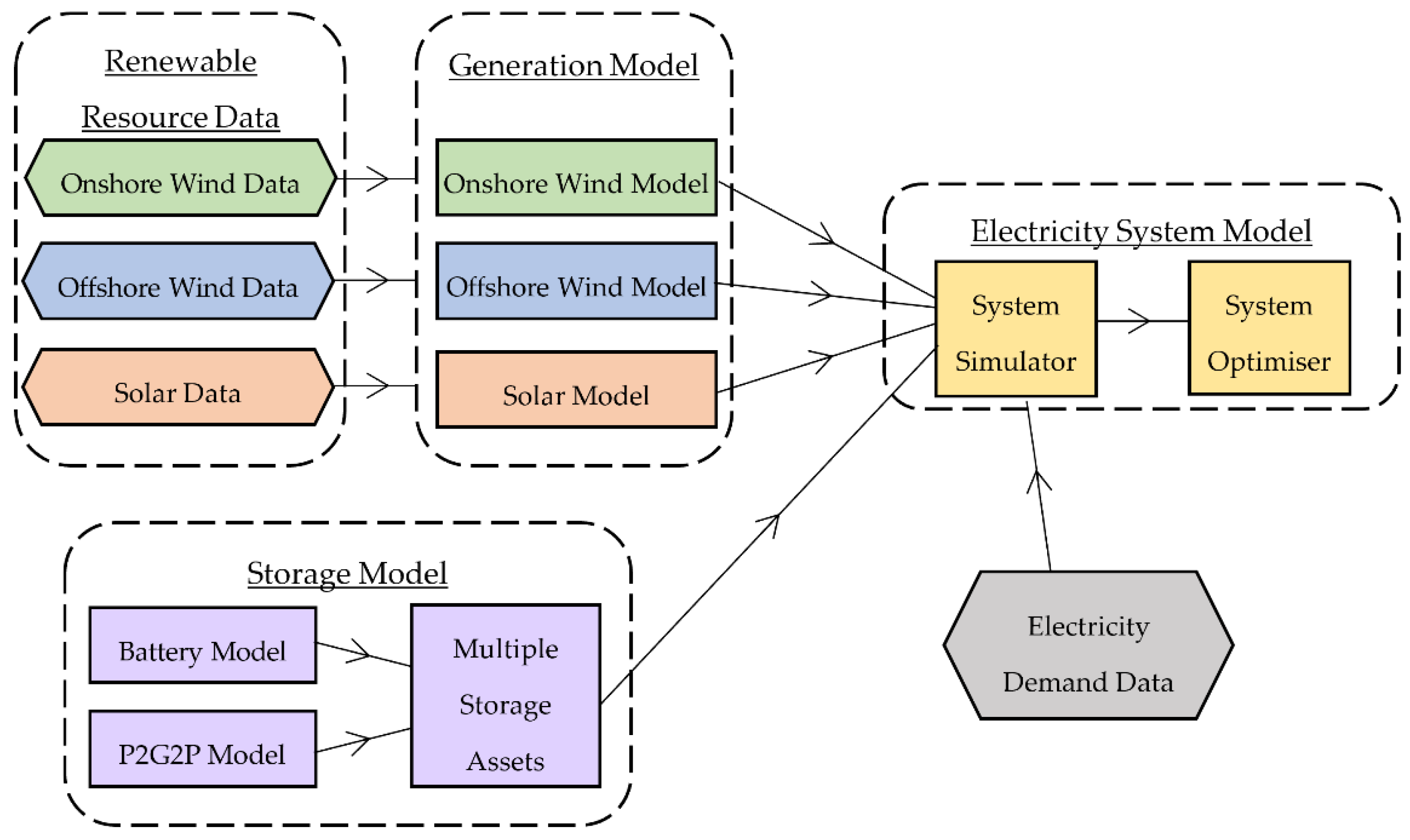
The SCORES model consists of several separate sub-models, which can be combined to carry out simulations or optimisations of a whole electricity system. A schematic overview of the model is shown in
Figure 1.
The model makes use of high-resolution renewable energy resource data, shown in
Figure 1 in the dashed box named “Renewable Resource Data”. These data include historic hourly wind speeds and solar irradiance data for a grid of datapoints across Great Britain and its territorial waters. More information is provided in
Section 2.2.
The “Generation Model” makes use of the Renewable Resource Data via technology specific sub-models for onshore wind, offshore wind and solar photovoltaics (PV). These sub-models include the technological parameters and relationships required to convert the hourly resource data into hourly generation profiles. More information on these sub-models is provided in
Section 2.3.1 and
Section 2.3.2. The Generation Model is a standalone model, which can be used to calculate various results, such as annual load factors for different technology types or locations.
The “Storage Model” is a separate model that is used to represent electricity storage assets. This model contains the necessary constraints to manage the charging and discharging of storage technologies. Sub-models are used to represent different storage technologies, such as batteries or power-to-gas-to-power (P2G2P). Additionally, the storage model contains a “Multiple Storage Assets” function, which manages the relationship between different storage technology types, for example, determining which technology should be charged or discharged first. The Storage Model is described in detail in
Section 2.4.
The Storage Model interfaces with the Generation Model, via the “Electricity System Model”. The key function of the Electricity System Model is to compare the electricity generation profiles generated in the Generation Model with pre-determined electricity demand data, generating an hourly profile of electricity “surplus” (when generation exceeds demand) or “deficit” (when demand exceeds generation). Based on this profile, operation of an electricity system can be simulated over one or more years. As described in detail in
Section 2.4, the “surplus” profile generated by the Electricity System Model is also used by the Storage Model in the simulation of storage operation.
The Electricity System Model is still in development, but is intended to include various other functions to provide overall system analysis. This will include modelling technology costs, and a system optimiser, which will seek the combination of generation and storage installed capacities that achieves the lowest overall system cost while still meeting required reliability levels. Details of this will be published in future work.
2.2. Renewable Resource Data
The SCORES model can make use of global reanalysis models such as the NASA Modern-Era Retrospective analysis for Research and Applications (MERRA-2) [
20]. This has a spatial resolution of 50 km and global coverage, meaning that SCORES could be applied to any country or energy system in the world.
In this study, MERRA-2 is used to provide the onshore wind speed data. For greater resolution and accuracy in the context of Great Britain, sources from the UK Met Office are used for offshore wind speeds and solar irradiance. The offshore wind speed data are sourced from the Met Office’s Virtual Met Mast (VMM) dataset [
21]. The VMM utilises data from Met Office regional-scale numerical weather prediction (NWP) models to which adjustments are applied to account for local complexity such as the effects of local topography and near-coast effect. It covers a period of over 34 years at 150 m height for 512 sites in regular spaced grids (30 km × 30 km) across Great Britain’s offshore sea water. The solar irradiance data are sourced from Met Office datasets from 80 observation centres across Great Britain, covering up to 10 years [
22].
Where there is not a data point at the specific location being simulated, a spatial interpolation is performed. The three closest data points are located and linearly weighted by their distance from the simulation point, such that the closest point is most strongly represented.
2.3. Generation Model
SCORES’ Generation Model contains a series of technology-specific sub-models. Each sub-model includes the relationships and parameters necessary to convert the hourly renewable resource data into power generation profiles. The sub-models are described in the following sub-sections.
2.3.1. Offshore Wind Model and Onshore Wind Model
Both the Offshore Wind Model and Onshore Wind Model use the same approach to convert wind speed data to power output. The only differences between the models are the wind speed data used and the turbine technology parameters.
To calculate the hourly power output profile, first the wind speeds in the renewable resource data are adjusted to account for differences in height between the wind turbine hub height
h and the height at which the wind speed data were measured,
href:
where
v is the wind speed at the wind turbine hub height
h;
vref is wind speed from the renewable resource data, measured at height
href; and
α is the wind shear coefficient, taken to be 0.143. The wind turbine “power curve” is then defined based on the wind power equation:
where
Pt is the theoretical wind turbine power output;
Cp is the power coefficient;
ρ is the air density;
A is the turbine rotor swept area and
v is the wind speed at the rotor hub height. In practice,
Cp is a non-linear function of the turbine’s tip speed ratio; however, in SCORES, it is assumed to be a constant value, derived from Equation (2) for the turbine’s power output at rated wind speed
vrated.
The actual wind turbine power output
P is then calculated from
Pt as follows:
where
vcut-in is the cut-in wind speed (at which the turbine begins outputting power);
vrated is the rated wind speed (at which maximum power output is first achieved); and
vcut-out is the cut-out wind speed (at which the turbine shuts down). The parameters
h,
A,
vcut-in,
vrated and
vcut-out are all input parameters that are defined based on the manufacturer specifications for the turbine being modelled. The details of the assumptions used for the offshore and onshore models in this study are shown in
Table 1.
2.3.2. Solar Model
The Solar Model converts the solar irradiance data to solar PV power output data. The hourly power output
of a solar PV installation of area
, subject to radiation
, is calculated as follows:
where
is a fixed efficiency parameter for the PV panel. Similarly, the installation area
relates to its nominal maximum power output
via a fixed area factor
:
The radiation seen by the PV installation,
, is derived from the global horizontal irradiation input data described in
Section 2.2. The method used follows the equations set out by Duffie and Beckman [
25], and is detailed in
Appendix A. The method accounts for the panel location, tilt and orientation, as well as how diffuse the irradiation is. The key panel parameters used in this study are shown in
Table 2. The PV nominal capacity is not defined as an input parameter, as it is varied depending on the total solar installed capacity that is modelled.
2.4. Storage Model
2.4.1. Storage Technology Parameters
One or more storage technologies may be included in the model. All modelled storage technologies follow the same operating principles, but are differentiated by technology parameters, which may determine their preferred mode of operation. The storage technology parameters that are modelled in SCORES are shown in
Table 3, with the values of those parameters that were used to model Li-ion batteries in this study.
A nominal battery storage or power capacity is not defined as an input, as this is determined by the total installed capacity of batteries. However, the parameters shown in
Table 3 are sufficient to determine the operating limits of the technology. For example, based on a maximum charging and discharging rates of 100% per hour, a battery with a nominal storage capacity of 20 MWh, would have a nominal power rating of 20 MW.
2.4.2. Storage Operation for a Single Storage Technology
The storage model is based on an hourly “surplus” profile
, which is defined as the total electricity generation minus the electricity demand:
where
is the hourly generation profile, determined by the Generation Model, and
is the hourly demand profile, a model input.
may be positive in the case of a generation surplus, or negative in the case of a deficit.
The storage model assumes opportunistic storage operation: in the event of a generation surplus (), the storage is charged at the maximum available rate; meanwhile, in a generation deficit (), the storage is discharged at the maximum available rate. The maximum available charging or discharging rate is constrained by a number of variables:
The total available surplus (or deficit) during the given time interval (the storage cannot continue charging if there is no more electricity available);
The remaining storage capacity (the storage cannot continue charging if it is already full);
The maximum charging or discharging rate of the technology (as defined in
Table 3).
The remaining storage inventory is tracked across the simulation, and the charging and discharging efficiencies are accounted for as electricity is either put into storage or withdrawn. Additionally, the storage inventory is depleted in each interval based on the self-discharge rate defined in
Table 3. Once the storage operation has been simulated for an entire time history, a new post-storage surplus profile will have been generated. Depending on the effectiveness of the storage technology, the new surplus profile may now be entirely positive, indicating that all generation deficits have been eliminated through storage. However, the post-storage surplus may still include negative values, indicating that there are time steps for which a generation deficit remains.
A “reliability” metric is used to measure the extent of remaining deficits. This metric is valuable for comparing the effectiveness of different generation and storage systems. Here we a metric previously used by Budischak et al. [
29]: the percentage of the simulation time for which the demand was met, such that reliability is defined as:
where
is the total number of timesteps where a deficit occurs (i.e., electricity demand exceeds supply, even after storage has been utilised), and
is the total number of timesteps in the simulation. This metric describes the percentage of time intervals for which demand could be met entirely with renewable electricity and storage. Although this does not capture the magnitude of energy shortfalls, as the storage is assumed to operate opportunistically (rather to maximise this metric) there is no danger of the system purposefully missing demand where a shortfall is unavoidable.
It should be noted that this specific definition of “reliability” is concerned only with the renewable generators, storage, and demand profile included in the model. Any “missed reliability” under this definition simply indicates that additional flexibility may be required, such as dispatchable generation or demand-side response. In the remainder of this article, the term “reliability” will only be used as defined above.
2.4.3. Multiple Storage Assets
Different storage technology types can be modelled concurrently in SCORES, for example, to include both Li-ion batteries and hydrogen storage in the same system. The same opportunistic storage algorithm is used; however, a precedence order must also be chosen to determine which storage technology type is charged and discharged first. Future work will investigate more dynamic precedence setting in order to maximise the overall system benefit. In this study, only one storage technology type (Li-ion batteries) was modelled.
2.5. Demand Data
The relationship between renewable generation and electricity demand will dictate the required amount of energy storage. Electricity demand is partially determined by human behaviour, and thus dependent on the weather. This complicates the problem of estimating the reliability of renewable electricity systems because generation will also be strongly weather dependent. Here, we propose using historic demand alongside historic weather data, so that this relationship is accurately captured.
For this study, electricity data were obtained from Gridwatch [
30], an API for accessing historic UK electricity demand. The demand is available at 5 min intervals; however, it was down-sampled to hourly resolution and missing points were forward-filled.
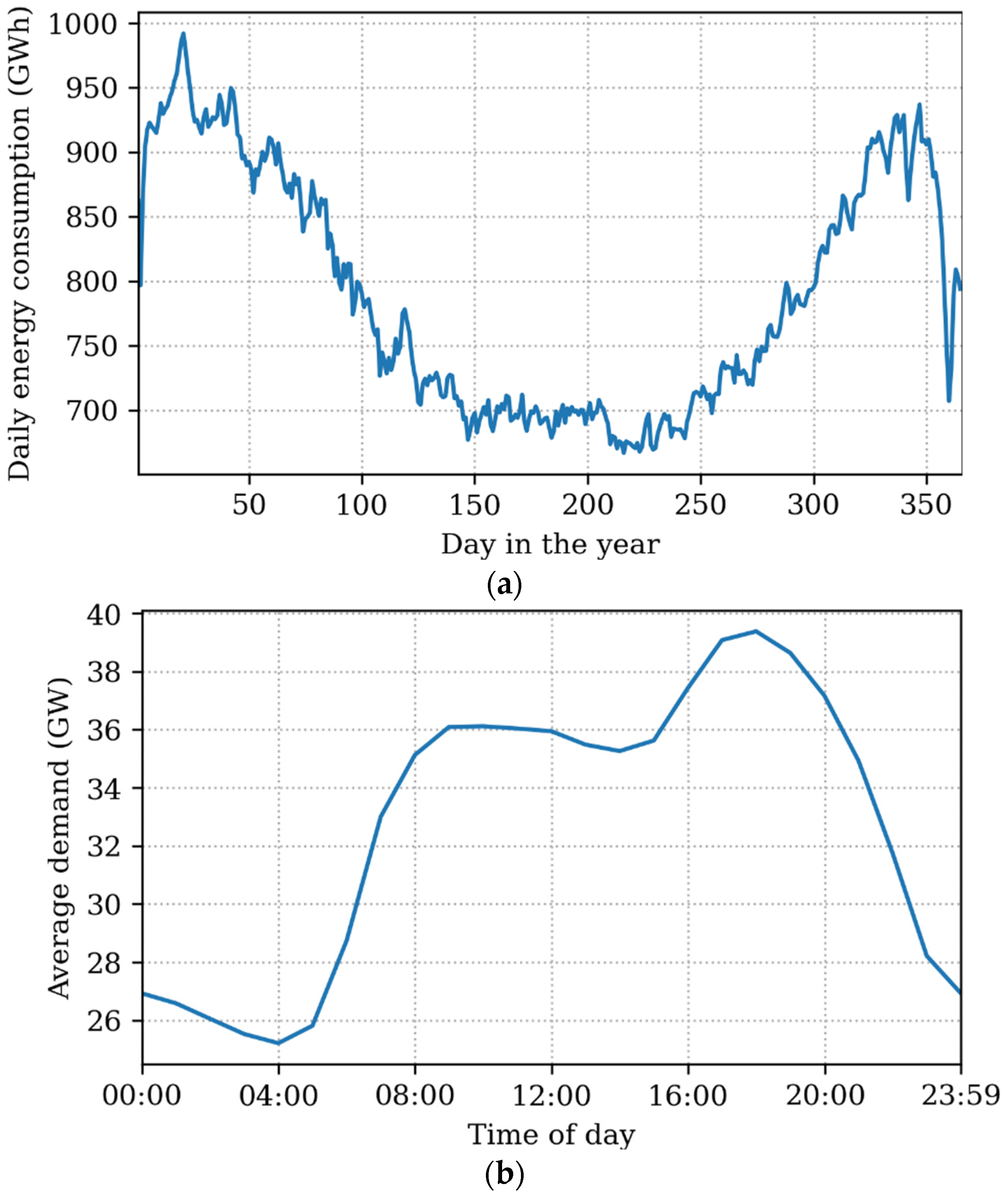
Figure 2 shows the resulting electricity demand profiles. As can be seen, there is significant variability across the year, with much larger electricity demands in winter. Demand is also much higher during the day than overnight, and with an early evening peak.
Although there are models of the future electricity profile (e.g., [
31,
32,
33]) these take a sample-day approach. This approach is not appropriate for estimating system reliability because both demand and renewable generation can have rare long events that must be accounted for—e.g., a two-week period of low wind output. We believe the proposed method is the most robust available for quantifying the reliability of an electricity system.
The limitation of using historic demand data in this way is that future changes to the electricity demand profile are not included. Electrification of transport and heating are likely to both increase total electricity consumption, and change its diurnal and seasonal profiles. It would be possible to model these additional loads and then superimpose them onto historic demand data. This will be explored in future work.
3. Results and Discussion
This section presents results generated with the SCORES model. A case study of Great Britain and its territorial water is modelled, with electricity generation made up of offshore wind, onshore wind, and solar power aided by battery energy storage. Offshore wind, onshore wind, and solar power plants are assumed to be evenly distributed across the territory. For all results in this section, the system is simulated at an hourly time step, using historic electricity demand and weather data between the years 2013 and 2019 inclusive; therefore, a total of 61,344 h were simulated. These results analyse the effect of sizing the various aspects of the system on the resultant reliability factor as defined by Equation (7).
3.1. Varying Installed Generation and Storage Capacity
The reliability of a renewable electricity system may be increased by increasing either the total installed generation capacity or the total installed storage capacity. Increased generation means that the storage is used less frequently, so it is more likely to be available to discharge at times of shortfall. By contrast, increased storage capacity means that a larger percentage of generation surplus can be shifted to meet demand. Here, we investigate how the reliability of the electricity system changes as one increases either the installed generation capacity or storage. We assume a fixed ratio of renewable energy capacity of 40% offshore wind, 30% onshore wind, and 30% solar (percentages taken by nameplate capacity, not energy generation).
Figure 3 shows the variation in system reliability for a range of system generation and storage capacities. Note that the “reliability” is as defined in Equation (7); therefore, “missed” reliability does not necessarily represent a system failure, but suggests that further alternative flexibility provision (such as dispatchable power generation or demand-side response) would be required.
Figure 3a shows five different total generation capacities, each with a range of storage capacities between 0 GWh and 800 GWh. At very low levels of storage the marginal utility of additional storage is high; i.e., a small further increase results in a substantial increase in reliability. However, as the amount of storage increases the marginal utility decreases, and for each installed generation capacity, the achievable reliability plateaus. In the cases where there is sufficient energy to meet all demand, theoretically close to 100% reliability should be possible (start-up effects of the simulation may prevent 100% from being reached). However, the cost of achieving an extra unit of reliability may become prohibitively high.
Figure 3b shows the variation in system reliability as the total generation capacity is increased from 55 GW to 170 GW for five levels of installed storage. Recall that generation capacity values are for total nameplate capacity rather than peak generation output (an important distinction as the peak output of the different renewables are unlikely to occur at the same time). For this range of values, total generation capacity has a more pronounced effect on reliability (although having energy storage significantly increases reliability).
Given the load factors of each renewable generator, the “average load factor” of the electricity generation system (with 40% offshore wind, 30% onshore wind and 30% solar) is 40%; therefore, a 60 GW system, for example, would only generate 24 GW on average. By comparison, the average electricity demand in the scenario is around 33 GW. From this, we can see that even in a system with “perfect storage”, a minimum generation capacity of around 83 GW would be required in order to meet the 33 GW “average demand” (thus achieving 100% reliability). As the results in
Figure 3 show, the storage system is non-perfect, so in fact system reliabilities remain well below 100% until generation capacity exceeds 100 GW, no matter how much storage is included.
3.2. Varying Generation Mix
As well as the total installed generation capacity, the relative sizes of the generation assets will influence system reliability.
Table 4 shows some metrics for the hourly generation profiles of different generation technologies. The generator’s load factor is calculated by dividing the average power output of the generator by its nameplate capacity, and for renewable generators, it is typically determined by the weather and the operating parameters of the generator. For example, solar generation has a significantly lower load factor than wind power due to the low number of sunlight hours per year. Load factor is important in this analysis because generators with higher load factors will generate more energy for a fixed installed generation capacity.
The generator’s Pearson coefficient and correlation with demand each give an indication of the degree to which the output of the generator matches the variations in demand. For example, as can be seen in
Figure 2, the UK’s electricity demand is lowest in the summer; meanwhile, solar power peaks in the summer, so seasonally the variation in solar power is not well aligned with demand. On the other hand, solar power is only available during the day, and the UK’s demand is higher in the daytime. This is important because greater misalignment of generation and demand suggests an increased reliance on energy storage. Correlation is quantified by scaling each signal to vary between 1 and 0 and calculating the average product between the two signals, such that the minimum value is 0% and the maximum value is 100%.
Finally, the correlation of each generator’s output with the other generators gives an indication of how well “matched” different generators are. It might be expected that generators with a low correlation would be more complementary in an electricity system, although in practice, it will depend on wider system dynamics.
The load factor for offshore wind is by far the highest, as is the correlation with demand. As they result in a higher energy generated (so larger area under the power curve) we can expect signals with a higher load factor may have a larger correlation with any signal. It is important to note that the load factors and correlation alone cannot dictate what the best mix of generation technologies is, as the correlation coefficient does not dictate the required energy storage capacity—this also depends on how long the energy needs to be stored for.
Therefore, in the following subsections, we will examine how the system reliability changes for different ratios of the three generation technologies, with a fixed amount of energy storage. Given that the load factor varies with the power sources, we present two cases: one with a fixed total capacity, and one with a fixed total energy generation. This will help to distinguish between the effect of the high load factor and the effect of the generation profiles.
3.3. Optimal Generation Mix with a Fixed Total Installed Capacity
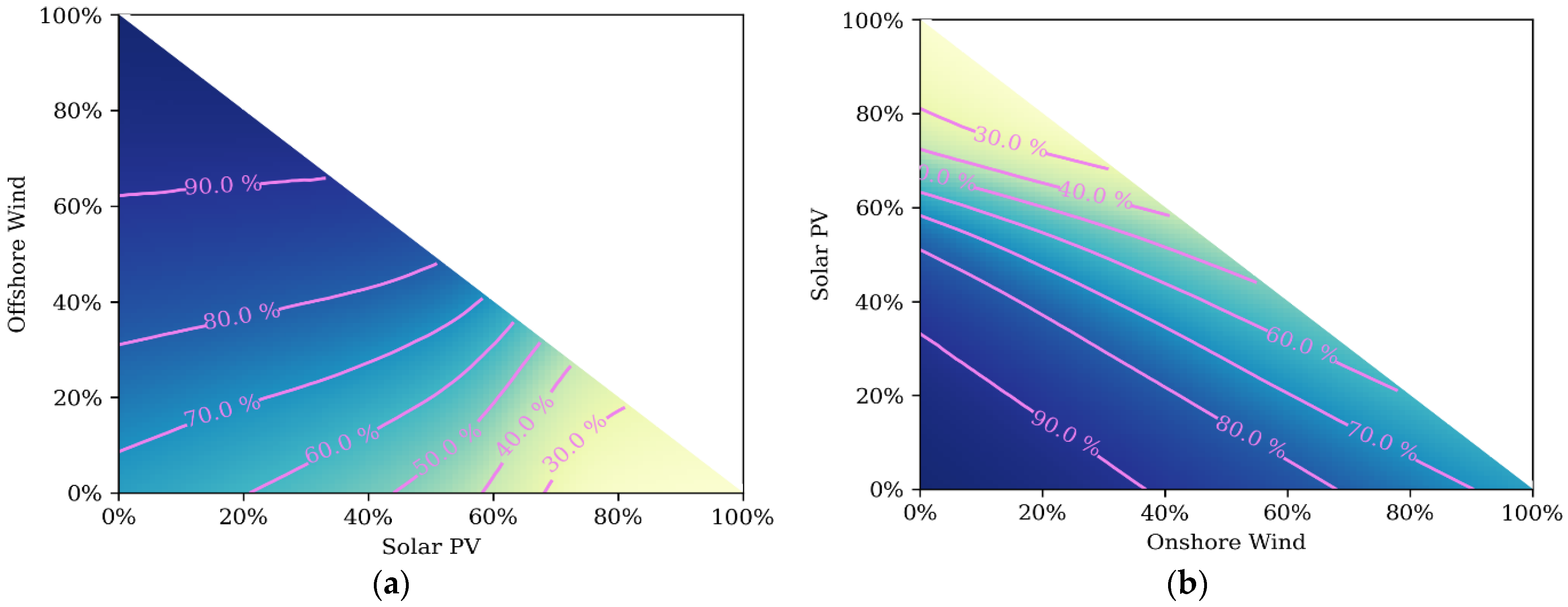
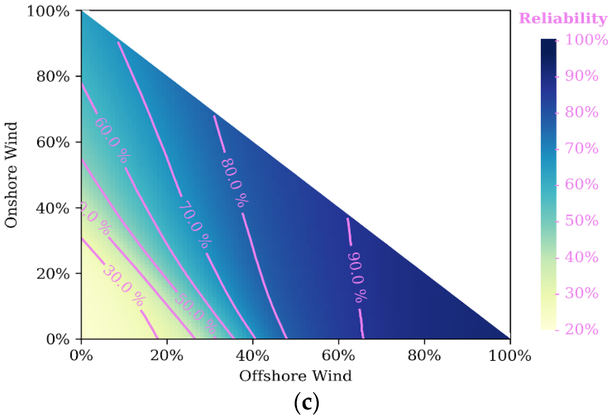
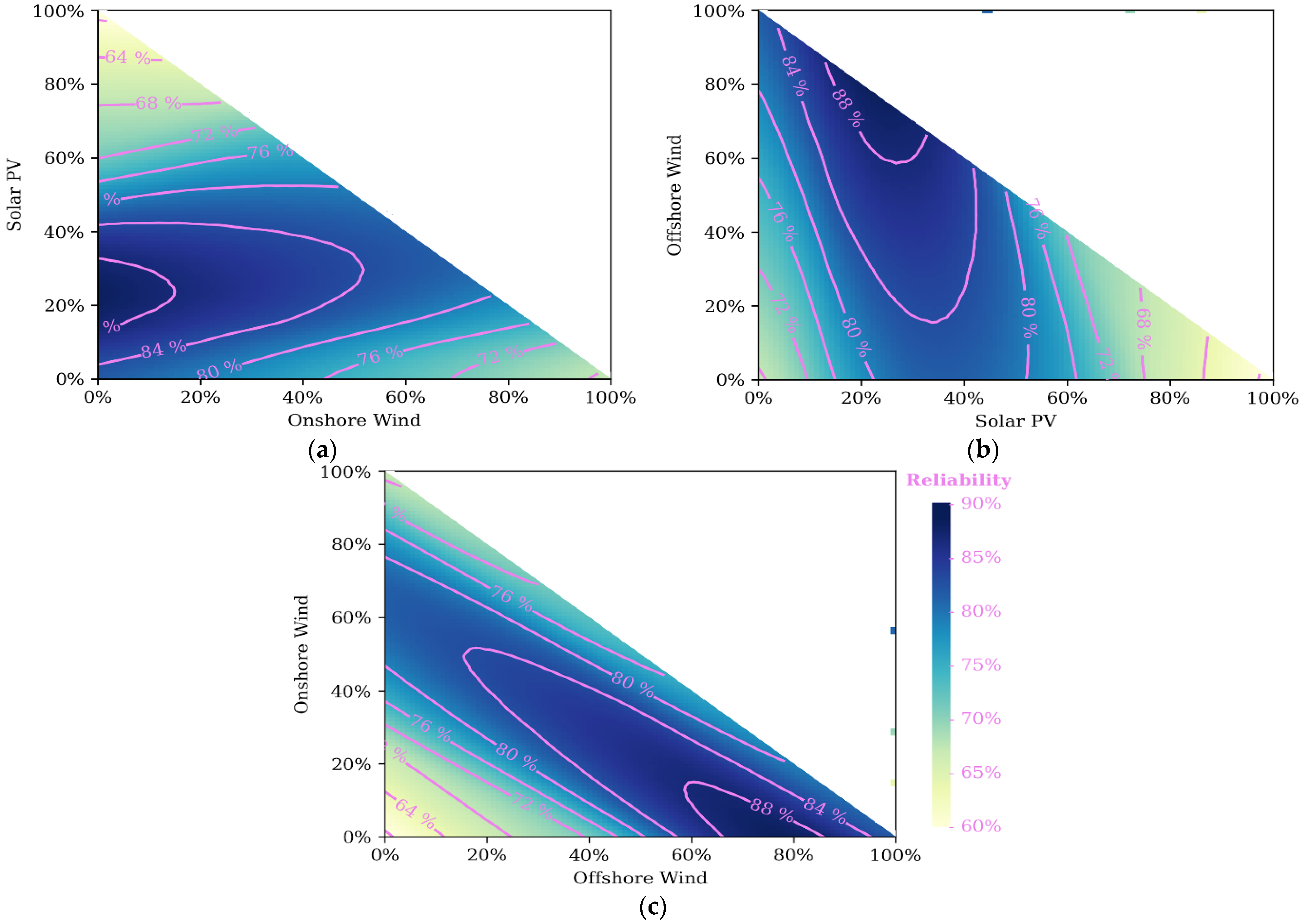
Figure 4 shows how the reliability of a system with 100 GW of total generation and 300 GWh of Li-ion battery storage changes with different relative installed capacities of the generator types.
The top-left
Figure 4a shows the percentage of total installed capacity provided by onshore wind on the x-axis, and the percentage provided by solar PV on the y-axis. The remaining capacity (summing to 100%) is provided by offshore wind. The other two
Figure 4b,c shows the same generator types but assigned to different axes so that the interplay between each of the generator types can be seen. Only the bottom triangle is shaded in each case as the sum of the contribution from each generator types cannot exceed 100%. Contour lines show lines of constant reliability, such that the generation mixes along the line will all have the same system reliability. It is interesting to consider the subset of generation mixes which create the same overall system reliability, because there may be political or economic considerations which favour one technology over the other.
The highest levels of reliability are found with a predominately offshore wind mix, which is likely caused because offshore wind has the highest load factor of the three generator types. A high penetration of solar power gives a low reliability regardless of the remaining mix between offshore and onshore wind. At high levels of offshore wind, the 90% contour is almost parallel to the y-axis—demonstrating that the reliability is almost the same regardless of the remaining make-up on onshore wind and solar. The contours show that the highest reliability levels are seen at, and close to, 100% offshore wind.
3.4. Optimal Generation Mix with a Fixed Annual Generation
Given that the total generation capacity is fixed at 100 GW in the above example, there is a distortion towards the generation technologies with the higher load factors. As offshore wind has the highest load factor, a larger percentage of offshore wind means that the total energy generation is higher. To compare how the generation mix aligns with the demand profile, we can instead fix the total energy generation.
Figure 5 shows plots with a fixed energy generation of 350.4 TWh/year, which is equivalent to 100 GW of generation with a 40% load factor. In this case, the range of reliability is much smaller, demonstrating that the quantity of energy had a large effect on the previous results. Whereas in the previous example, the contours centred around the 100% offshore wind point, here, the optimal reliability occurs at around 75% offshore wind, 25% solar.
The dominance of offshore wind is likely because it has the highest correlation with demand (as shown in
Table 4). Solar power is likely chosen because it complements the offshore wind, meaning that the solar is likely to be high when the offshore wind is low. This can also be seen from the correlation values: solar and offshore wind have less than a 7% correlation. There is little role for onshore wind, because it is more strongly correlated with offshore wind (28%), so compared to solar, it would be less effective at filling in the shortfalls of offshore wind.
To further understand why the reliability varies this way with generator mix, it is useful to look at how the storage is used.
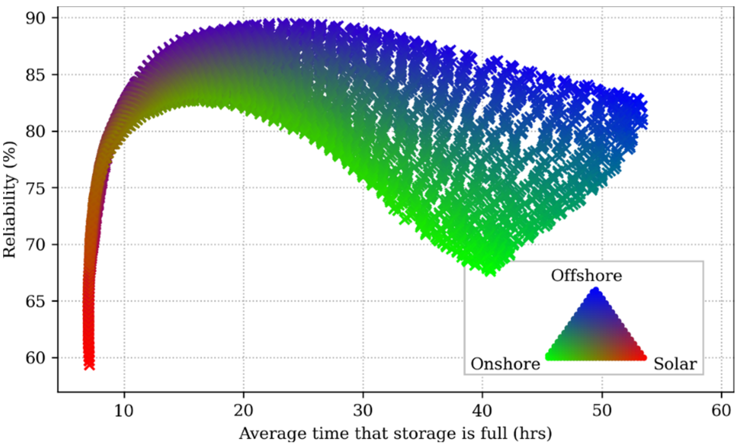
Figure 6 shows a scatter plot of the reliability of a system versus the average number of consecutive hours for which the storage is fully charged. This gives an indication of how long energy is generally stored for, as while the storage is fully charged, it is not being used. The systems were chosen using the same assumptions as in
Figure 5. The colour of each marker signifies the relative contribution of each generation technology to the total energy generation; for example, fully blue markers denote a 100% offshore wind powered system.
The system designs that are most reliant on solar power have the shortest durations for which the storage is fully charged, in the range of 5 to 16 h. Clearly, this storage operation is driven by the day/night cycle of solar power. Meanwhile wind-based systems have much longer full-storage durations on average, indicating that the storage is used less frequently in those systems. The highest reliability systems have average full-storage durations of around 23 h, whilst for some systems, this is in excess of 50 h. These long storage durations may present challenges in finding a viable economic case for the storage when it is used so infrequently. However, they also show the opportunity for suitable long-duration storage technologies, with large capacity and low self-discharge.
4. Summary and Conclusions
In this paper, we developed a model to quantify how the reliability of renewable electricity generation changes with battery energy storage, given the geographic location. Separate models were developed for offshore wind, onshore wind, and solar power, which use hourly wind speed and solar irradiance data to estimate generation output. As a case study, we considered the reliability with which the UK’s electricity demand could be met with renewable generation. First, we considered a fixed capacity generation mix of 40% offshore wind, 30% onshore wind, 30% solar and investigate how the sizing of total generation and storage affects the reliability of the system. We showed that introducing storage to an electricity system significantly increases its reliability, but as the total level of storage increases, the marginal benefit of further storage quickly diminishes.
Second, we considered how the mix of the generation technologies affects the reliability of the system. We found that, when capacity is held constant, an entirely offshore wind mix is the most reliable, but this was largely because the load factor for offshore wind is much higher than the other two sources. When energy generation was held constant, the most reliable mix was approximately three-quarters offshore wind and one-quarter solar power.
Finally, we explored how the storage is used in systems with different generation mixes. We showed that high-solar systems use shorter duration storage, but the most reliable systems have storage durations greater 20 h. Given that the economic viability of energy storage often requires a high usage rate, incentivisation methods or alternative storage technologies need to be investigated.
The results of the case study provide some insights into the design of a low-carbon electricity system in the UK. With appropriate amounts of energy storage, electricity demand can be met with a high degree of reliability using only renewable generation technologies. In the UK, when total generated energy or generated power is constrained, the most reliable systems are dominated by offshore wind. When total generated energy is constrained, adding solar power to the offshore wind increases reliability due to its complementary nature to offshore wind.
Additionally, more general conclusions about sizing a renewable electricity system can be formed. In this study, we developed the SCORES model and demonstrated how it can be used to explore the interactions of different electricity generation technologies, storage, and electricity demand. The case study showed that neither correlation nor load factor were accurate predictors for the resulting reliability, meaning that hourly simulations are necessary.
It is nontrivial to optimally size a renewable electricity system because there are at least four variables to consider: the quantity of each renewable resource and the amount of energy storage. Here, we demonstrated example results that can be visualised by fixing certain quantities, such as the total installed storage capacity. In practice, system planners will have their own constraints and we hope that our open source model will allow them to explore potential future system designs.
This study has focused on system reliability as the key metric, but with future work, we plan to expand SCORES to include optimisation of system cost, which will enable us to investigate the trade-offs between cost and reliability. By including additional storage technologies with different performance parameters, we also plan to explore the relative merits of different generation and storage technologies in more detail.
