1. Introduction
Carbonized palm kernel shell (CPKS)-reinforced epoxy resin composites represent a sustainable bio-based material with strong potential for electrical insulation applications. Palm kernel shells, an abundant agricultural waste from palm oil processing (particularly relevant in regions like Nigeria), are carbonized under controlled low-oxygen conditions to produce a char-like particulate filler. When incorporated into epoxy resin, the resulting composite enhanced key insulation properties: electrical resistivity and dielectric strength (breakdown strength) [
1,
2]. However, additive manufacturing (AM or 3D printing) of CPKS-reinforced epoxy resin composites offers a promising but underexplored route for producing lightweight, sustainable electrical insulation components in the automotive and aerospace sectors. CPKS, which serves as a bio-based particulate filler that traditionally enhances insulation in cast or molded epoxy, increases AC breakdown voltage up to ~2× and meets the ≥108 Ω/mm resistivity threshold at optimal low-percentage loadings [
1,
3].
The reliability and performance of electrical equipment are strongly influenced by the properties of the insulating materials used. Traditional insulators such as mica, rubber, and marble—derived from natural sources—offer limited dielectric properties and have largely been replaced by synthetic polymers, which provide superior electrical insulation [
4,
5]. Technologists and researchers have shown increasing interest in natural fibers as reinforcements for sustainable composites, driven by global environmental concerns, regulatory pressures for reduced carbon emissions, and the need for lightweight, renewable materials in industries like automotive and construction sectors. This interest stems from the shift away from petroleum-based synthetics, which contribute to pollution and resource depletion, toward bio-based alternatives that align with circular economy principles [
5].
However, synthetic insulators often come with drawbacks: high production costs, environmental concerns, and potential health hazards [
5,
6]. These challenges have driven the search for alternative materials that are both effective and sustainable. Recent research highlights the potential of agricultural waste rich in cellulose, such as coconut husk, bagasse, cashew nut liquid (cardanol), and palm kernel shell, as eco-friendly insulating materials [
2,
7,
8]. Recent reviews highlight how natural fibers offer a pathway to eco-friendly innovations, with the production of natural fiber composites growing rapidly in regions like Europe, where they now comprise up to 30% of the composite market alongside synthetics. The focus is on valorizing agricultural byproducts and wastes, turning them into high-value materials that minimize environmental impact while maintaining competitive performance [
2,
5,
7]. Traditional manufacturing faces challenges like filler agglomeration (causing defects that degrade dielectric strength), material variability (natural waste), energy waste in processing, and high scrap rates; lean principles directly target these issues [
1]. Lean intelligent manufacturing merges lean philosophy (waste elimination via value stream mapping, 5S, kaizen, and just-in-time manufacturing) with intelligent (data-driven and AI-enabled) systems. Industry 5.0 develops this further by prioritizing three pillars beyond Industry 4.0’s automation focus: human-centricity (worker well-being and collaboration), sustainability (circular economy and eco-materials like agro-waste), and resilience (adaptability to disruptions via predictive systems) [
1]. The resulting conceptual model—termed here a Lean Industry 5.0 Introduction Framework for CPKS-Epoxy Insulation Composites (LI5-CPKE-Intro)—has a human-centric framework [
1].
The selection of insulation materials requires a thorough understanding of two critical properties: electrical resistivity, which differentiates insulators from conductors, and dielectric strength, the maximum electric field a material can withstand without failure [
9]. Dielectric breakdown triggered by excessive temperature, prolonged voltage stress, humidity, or frequency-related losses marks the end of an insulator’s effectiveness [
10,
11]. Moisture absorption (hygrothermal aging) plasticizes the epoxy, promotes hydrolysis at interfaces (especially with hydrophilic biomass fillers), and introduces ionic conduction paths, significantly degrading resistivity, increasing loss, and lowering breakdown strength. Thermal–oxidative or electrical aging can lead to chain scission, void formation, and filler–matrix debonding, progressively reducing insulation reliability over service life [
10,
11,
12].
Breakdown mechanisms include thermal breakdown, due to heat accumulation beyond dissipation capacity [
13], and avalanche breakdown, driven by electron collisions and ionization within the material [
14]. Furthermore, dielectric strength is not a fixed property; it varies with factors such as thickness, temperature, and aging [
15,
16].
However, in spite of all the progress made by researchers in agro-waste materials, critical gaps remain. Limited research has examined epoxy resin-based composites specifically reinforced with PKS for insulation purposes. Furthermore, carbonization has shown promise in enhancing the performance of agro-waste, but there is little systematic work linking dielectric strength and resistivity properties to a specific carbonization temperature range. This research addresses these gaps by characterizing the dielectric strength and resistivity properties of composites made from carbonized PKS with epoxy resin as the binder.
This study investigates the resistivity and dielectric strength performances of carbonized palm kernel shell-based insulation, aiming to assess its suitability as a cost-effective and environmentally responsible alternative for electrical applications.
3. Results and Discussion
The dielectric strength of each sample was calculated using the breakdown voltage (BDV) and sample thickness, according to the following equation:
where
Emax is the dielectric strength (kV/mm), V
BD is the breakdown voltage (kV), and D is the thickness of the sample (mm). The results are presented in
Table 1,
Table 2 and
Table 3.
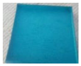
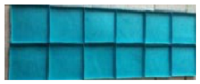
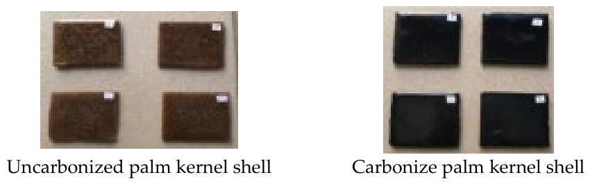
To evaluate electrical resistivity, samples were molded into rectangular shapes with dimensions of 50 mm × 50 mm × 3 mm, as shown in
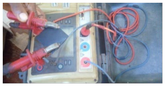
Figure 8. Copper wires (2.5 mm diameter; 1000 mm length) were clipped to opposite edges of each specimen and connected to a Digital Mega Insulation Tester (Megger MIT 520/2), as shown in
Figure 11. The resistance was measured in gigaohms, and the volume resistivity
ρ of each specimen was calculated using the following formula:
where
ρ = volume resistivity (Ω·mm);
R = measured resistance (Ω);
A = cross-sectional area of the specimen (mm
2); and
L = length between electrodes (mm) [
11]. The experimental results are shown in
Table 1,
Table 2 and
Table 3 and
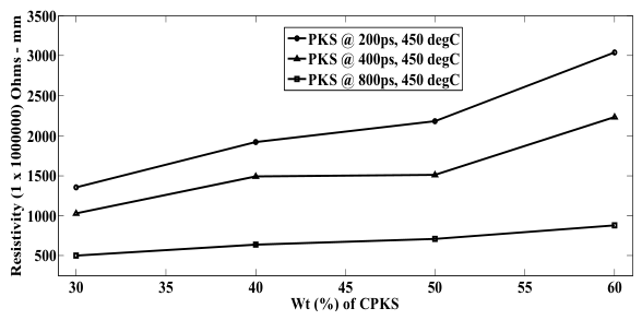
Figure 11,
Figure 12,
Figure 13,
Figure 14,
Figure 15,
Figure 16 and
Figure 17.
3.1. Effect of Particle Size and Weight Percentages on Carbonized Palm Kernel Shell-Reinforced Epoxy Matrix Composites
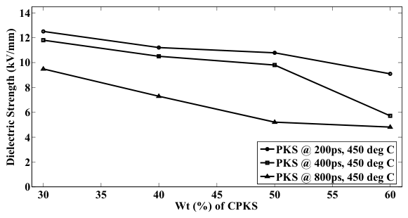
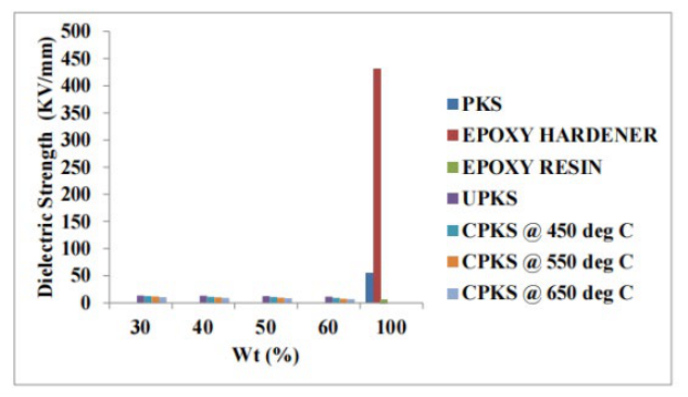
As shown in
Figure 12 and
Figure 13, composites reinforced with smaller particle sizes exhibited superior dielectric performance across all weight percent (wt%) reinforcements. This behavior can be attributed to the finer particles dispersing more uniformly within the epoxy matrix, which enhances wetting and promotes stronger interfacial bonding between the filler and the resin, as shown in
Figure 14. In contrast, larger particles offer a reduced surface-area-to-volume ratio, limiting their dispersion and interaction with the matrix, thereby weakening the filler resin bond.
It was also observed that increasing the filler loading (wt%) led to a reduction in dielectric strength. At lower filler contents, particles are more evenly distributed. This supports better wetting and interfacial adhesion. However, higher filler content tends to agglomerate, leading to poor dispersion and reduced bonding integrity. Superior breakdown at lower loadings (<30 wt%) and smaller sizes (200 µm) stems from enhanced dispersion, reducing agglomeration-induced field concentrations and defects. Quantitatively, poor dispersion at higher loadings or larger sizes increases local field enhancement factors (often modeled via finite element analysis as 2–5× in clusters), promoting partial discharge and treeing initiation. Better dispersion minimizes interfacial voids, improves charge trapping at well-bonded interfaces (reducing free carrier mobility), and homogenizes electric field distribution. In natural filler systems, dispersion quality directly correlates with percolation threshold, below which fillers act as barriers to charge transport, enhancing strength, and above which conductive pathways or defects dominate, reducing it by 20–50% or more. SEM-supported quantitative metrics (like cluster size distribution and void fraction) confirm that optimal dispersion (achieved at smaller sizes or loadings) suppresses mechanisms like interfacial polarization, excess, and void-initiated breakdown. On the other hand, resistivity was found to increase with both particle size and filler content. This trend can be explained by the increased porosity introduced with larger particles and higher wt% reinforcements, as shown in
Figure 15. These pores, often air-filled, act as high-resistivity zones since air has an effectively high electrical resistance. As porosity increases, so does the overall resistivity of the composite material.
The reduction in dielectric or breakdown strength with higher filler loading is attributed to increased defect densities and inhomogeneities introduced by the filler particles. At low loadings, well-dispersed fillers can enhance dielectric performance through interfacial trapping of charge carriers or improved heat dissipation. However, as loading increases, agglomeration becomes prominent, forming clusters that act as local field concentrators and creating high-stress regions prone to partial discharge initiation and premature breakdown. Resin starvation occurs in inter-particle regions, where insufficient epoxy resin fails to fully wet or impregnate filler aggregates, leading to micro-voids or poor matrix coverage that serves as weak points for electrical treeing. Interfacial defects, such as debonding and voids at filler–matrix interfaces, exacerbate charge accumulation and localized field enhancement, reducing overall insulation integrity. These effects are exacerbated in micron-scale natural fillers like carbonized PKS, which have irregular morphology and surface porosity, promoting agglomeration during hand lay-up processing. The pores in carbonized PKS (enhanced at higher temperatures due to volatile escape) have dual, loading-dependent effects. With low filler contents, isolated porous fillers introduce air voids (ꜫr=1) that dilute overall permittivity and trap charges, slightly increasing effective resistivity by reducing conductive pathways. However, with higher filler contents, pores exacerbate certain issues; they promote resin starvation (incomplete wetting), creating micro-voids at interfaces or within clusters, which act as weak points for partial discharge and field concentration (reducing breakdown by providing initiation sites for electrical trees). Porous fillers also facilitate moisture ingress or gas trapping, lowering long-term resistivity. Thus, while intrinsic filler porosity may insulate internally, inter-particle or interfacial defects from poor impregnation dominate at high loadings, leading to a net reduction in strength despite any resistivity gain in isolated cases.
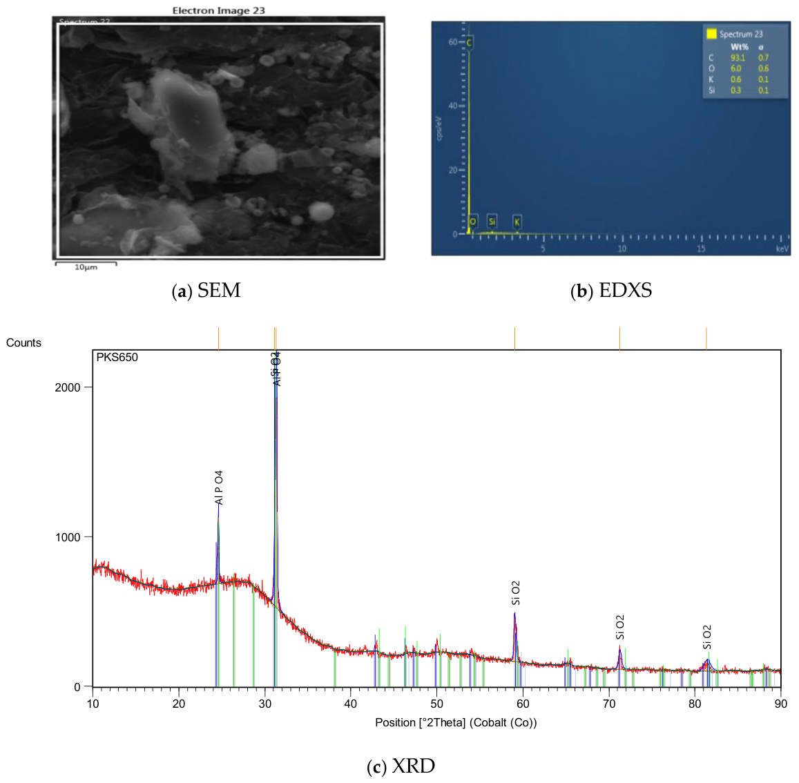
Particle size also influenced performance, where larger particles increased resistivity due to enhanced pore formation. At 550 °C, filler dispersion remained largely homogeneous with minimal voids, preserving good filler–matrix bonding and yielding favorable insulating properties. However, at 650 °C, the SEM images in
Figure 15 revealed increased porosity, weak bonding, and filler agglomeration. These structural issues led to poor interfacial contact and a drop in electrical insulation performance. SEM micrographs reveal that higher carbonization temperatures, such as 650 °C, produce fillers with greater porosity due to enhanced volatile release, char restructuring, and rougher, more irregular surfaces, which hinder effective wetting and interfacial adhesion with the epoxy matrix. This results in increased micro-voids and gaps at the filler–matrix interface, acting as sites for charge trapping and partial discharge. It also results in weak bonding, promoting debonding under electric stress and facilitating propagation of electrical trees. It results in higher porosity within fillers, potentially allowing internal gas pockets or moisture ingress, further degrading insulation. These microstructural changes directly correlate with observed deterioration in dielectric performance, such as reduced breakdown strength and increased dielectric loss at higher carbonization temperatures, as porous, poorly bonded fillers introduce more defect sites and lower effective resistivity. Lower-temperature carbonized fillers (450–550 °C) retain more functional groups for better compatibility, leading to improved interfacial integrity and superior electrical insulation. This correlation strengthens the conclusion that moderate carbonization optimizes filler microstructure for dielectric applications.
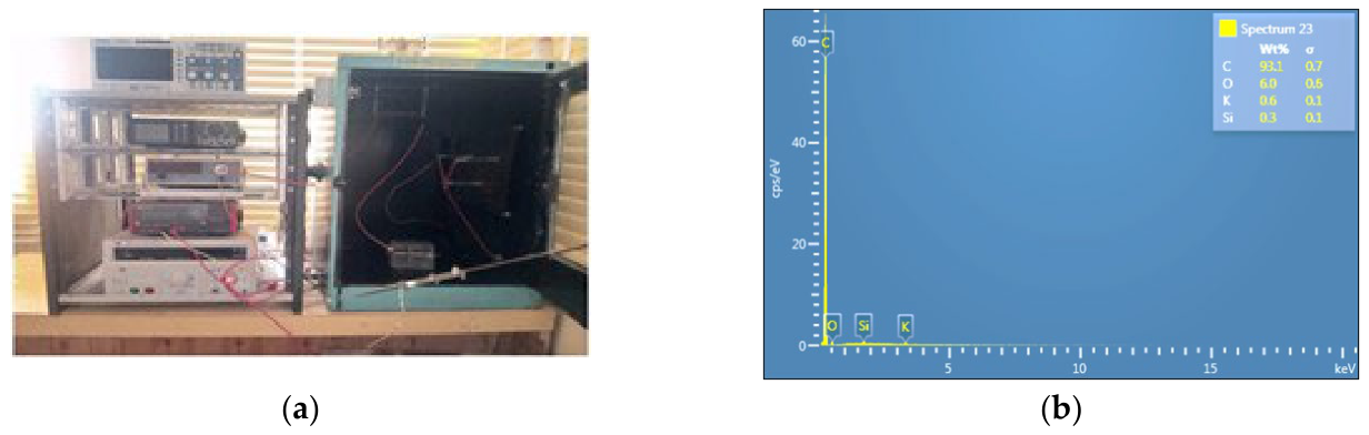
EDXS images in
Figure 15 show elemental composition, revealing that carbon has the highest percentage composition, which accounts for the increased performance of the samples.
The XRD patterns indicate predominantly amorphous carbon structures across the 450–650 °C range with no sharp crystalline peaks corresponding to graphitic ordering, such as no prominent (002) peak at ~26° 2θ or detectable radioactive or inorganic phases, confirming the purity and disordered nature of the carbonized PKS fillers. With increasing carbonization temperature, subtle shifts occur, progressive loss of oxygen-containing groups leads to higher fixed carbon content, and incipient short-range ordering, such as broadening or narrowing of amorphous humps, through full graphitization typically requires >1000–1200 °C in biomass-derived chars without a catalyst. At 650 °C, enhanced aromatic condensation increases electrical conductivity slightly due to delocalized πelectrons, which may contribute to higher dielectric loss or reduced breakdown by facilitating charge transport. Lower temperatures preserve more insulating character with residual polar groups. This temperature-dependent evolution from amorphous, oxygen-rich char to more condensed, semi-aromatic structures explains the observed trends in dielectric behavior, enhancing the mechanistic insight into filler property tuning.
While XRD shows no radioactive phases, trace mineral phases (e.g., silicates and oxides from biomass ash) in carbonized PKS can influence insulation via having higher permittivity/conductivity than pure carbon, introducing interfacial polarization (the Maxwell–Wagner effect), and increasing dielectric loss at low frequencies, thereby acting as charge-trapping sites if insulation occurs (e.g., silica-like), potentially enhancing break down strength modestly by hindering carrier mobility. If the materials are semi-conductive (e.g., metal oxides), they may create local conductive paths at high loadings, reducing resistivity. Overall, low ash content in PKS minimizes negative impacts, contributing to stable insulation; however, mineral heterogeneity can cause slight field distortions or loss increases compared to pure synthetic fillers.
3.2. Effect of Temperature Variation on Carbonized Palm Kernel Shell (PKS)-Reinforced Epoxy Matrix at 200 µm
The carbonization temperatures of 450 °C, 550 °C, and 650 °C were chosen to correspond with the primary thermal decomposition stages of lignocellulosic biomass during carbonization, allowing investigation into how the progressive structural changes in the filler influence the dielectric properties of the resulting composites. The carbonized palm kernel shell (lignocellulosic biomass) consists of hemicellulose, cellulose, and lignin, which decomposeat distinct but overlapping temperature ranges. Hemicellulose decomposes first in the range of ~200–350 °C, releasing volatiles and initiating early structural breakdown. Subsequently, cellulose decomposes between ~300 and 400 °C, involving depolymerization and major volatile release. Lignin decomposes over a broader and higher range, starting from ~200 °C, but with significant charring and slow degradation from ~350–500 °C up to 700–900 °C, contributing to aromatic char formation. The temperature of 450 °C was chosen to target the completion of hemicellulose and cellulose decomposition, whereas 550 °C was selected to capture the onset of more extensive lignin decomposition and secondary reactions, leading to increased aromaticity, reduced oxygen content, and enhanced porosity in the filler. But 650 °C promotes advanced carbonization, further increasing fixed carbon content and electrical conductivity due to graphitic development, while minimizing residual volatiles. A lower temperature preserves more polar functional groups and potentially increases dielectric strength, while higher temperatures yield more inert and conductive chars and potentially lower breakdown strength (dielectric strength).
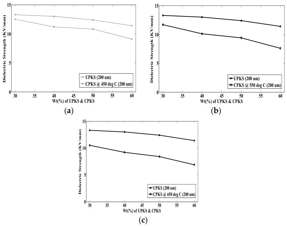
Figure 14 and
Figure 15 show that uncarbonized composites exhibit the highest dielectric strength, which is attributed to the presence of organic functional groups within the palm kernel shell (PKS). Among the carbonized samples, the optimum dielectric performance was observed at a carbonization temperature of 450 °C. Beyond this point, dielectric strength declined progressively up to 650 °C, indicating that higher carbonization temperatures adversely affect insulation performance.
This reduction is primarily due to the formation of micro-pores during carbonization, which compromises the material’s density and interfacial bonding. As carbonization progresses, total pore volume increases, and the poor adhesion between the filler and the matrix is further exacerbated by surface silica layers, which are remnants of the silicon–cellulose membrane that hinder bonding.
Moreover, excessive carbonization can lead to particle agglomeration, impeding uniform distribution in the epoxy matrix and increasing void formation. These micro-voids serve as points of dielectric failure, reducing overall performance.
Dielectric strength was also found to depend on filler loading and particle size. At 30 wt%, composites demonstrated optimal strength, attributed to effective wetting and sufficient resin availability for bonding. Higher filler contents introduced more porosity due to resin insufficiency, weakening the filler–matrix interface.
Additionally, smaller particle sizes (200 µm) consistently outperformed larger ones (400 and 600 µm) due to better dispersion, improved interfacial contact, and reduced internal voids. Hence, both moderate filler loading and finer particle sizes contribute to enhanced dielectric properties. At ~30 wt% PKS, dielectric strength peaks due to balanced filler reinforcement (charge trapping without excessive defects) while mechanical properties (tensile/flexural) benefit from moderate loading, avoiding agglomeration/resin starvation. Higher loading compromises both insulation (more voids/defects) and mechanics (brittleness and poor bonding). Long-term durability is supported by epoxy’s stability and PKS’s char inertness, but interfacial moisture sensitivity requires attention. This optimum provides a good insulation–mechanical trade-off for sustainable applications, with potential enhancements via treatments for extended aging resistance.
Measurements were conducted at room temperature (~25–30 °C) and low humidity to establish baseline properties. Real-world insulation performance is influenced by environmental factors as follows. Temperature variation: Elevated temperatures accelerated molecular mobility, increasing dielectric loss and permittivity while potentially reducing breakdown strength due to thermal expansion mismatches, softening of the epoxy matrix, and enhanced charge carrier mobility. In natural filler composites, differential thermal expansion may worsen interfacial defects. Humidity: Moisture absorption (hygrothermal aging) plasticizes the epoxy, promotes hydrolysis at interfaces, especially with hydrophilic biomass fillers, and introduces ionic conduction paths, significantly degrading resistivity, increasing loss, and lowering breakdown strength. Long-term aging: Thermal oxidative or electrical aging can lead to chain scission, void formation, and filler–matrix debonding, progressively reducing insulation reliability over service life. These factors are particularly relevant for outdoor or high-voltage applications of sustainable composites. Elevated temperatures (>50–100 °C) typically reduce dielectric strength and resistivity in epoxy composites due to increased molecular mobility, enhanced charge carrier generation/migration, thermal expansion mismatches (worsening interfacial defects in natural fillers), and potential softening/degradation of the matrix. For PKS/epoxy, hydrophilic char may absorb moisture, accelerating hygrothermal effects and ionic conditions. Thermal cycling exacerbates debonding/void growth, promoting treeing and progressive failure. A20–50% drop in strength is expected at 80–120 °C (common in insulation service), with natural fillers showing greater sensitivity than mineral ones due to organic residues. Long-term exposure could lead to oxidative aging, further degrading performance.
3.3. Effect of Carbonization and Filler Composition on Electrical Resistivity
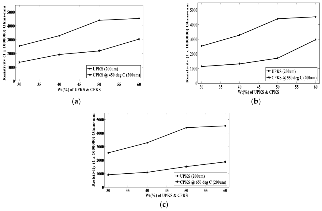
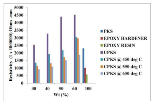
Electrical resistivity, as shown in
Figure 16 and
Figure 17, decreased with increasing carbonization temperature within each filler wt% but increased across wt% levels. This trend is due to the thermal degradation of cellulose and loss of polar groups during carbonization, which enhances the formation of conductive graphitic structures. At higher temperatures, more carbon atoms rearrange into graphene-like layers, with the primary conductive phase resulting in lower resistivity.
Despite this, the inclusion of epoxy resin and carbonization improved resistivity compared to pure PKS, possibly due to the non-conductive nature of the matrix. Among the compositions, 60 wt% fillers demonstrated the best resistivity, outperforming lower wt% (e.g., 50% and 40%), which had better dielectric strength. Lower filler content benefits from better resin wetting, but higher content can create a denser, more resistant structure if dispersion is maintained. The resistivity decreases as carbonization temperature rises from 450 to 650 °C due to progressive graphitic evolution: loss of oxygen groups, increased aromatic condensation, and formation of extended sp2 domains with delocalized π-electrons, enhancing charge mobility. At ~550–650 °C, short-range ordering creates semi-conductive pathways (conductivity rises from the ~10−10 to 10−6 W/mK range in similar biochars, transitioning from highly insulating (amorphous, oxygen-rich char) to semi-conductive (incipient graphitic)). Full graphitization (>1000 °C) would further increase conductivity, but at these temperatures, the shift explains higher dielectric loss and lower breakdown in higher temperature fillers.
Compared to commercial insulating materials such as unfilled epoxy, silica-filled epoxy, or mineral-filled resins used in bushings or cables, these PKS-reinforced composites offer advantages in sustainability and potentially comparable or tunable dielectric properties at optimized loadings or temperatures. While commercial materials often exhibit higher breakdown strengths due to better dispersion, nano-scale fillers or synthetic reinforcement, and proven long-term stability, our PKS composites show competitive performance in DC insulation with added benefits of cost-effectiveness and environmental friendliness. For instance, at moderate loadings, dielectric constants remain low (suitable for insulation) though losses may be slightly higher than ultra-pure commercial epoxies. This positions PKS composites as viable eco-friendly alternatives for non-critical or emerging applications such as low-to-medium-voltage insulators, which are structural composites with insulation functions, with room for improvement via surface treatments or hybrid fillers to approach commercial benchmarks. Commercial epoxy composites with micron-scale alumina (Al
2O
3), silica (SiO
2), or mica fillers often achieve higher DC breakdown strengths, frequently 50–80 KV/mm or more under similar ramp-test conditions like ASTM D149 [
17] equivalents, due to superior dispersion, lower defect density, and inherent high resistivity of these inorganic fillers. For example, alumina epoxy micro-composites can reach 60–70 KV/mm DC, while optimized nano-modified or dual-interface alumina systems exceed 67 KV/mm DC with reduced loss. Mica-filled epoxies are valued for high-voltage applications, often showing enhanced AC breakdown at a ~30–50 KV/mm peak and thermal stability. Silica-filled systems provide excellent insulation with low loss but may have slightly lower strength unless they are nano-enhanced. These PKS composites offer advantages in sustainability, cost, and renewability with comparable performance at low-to-moderate loadings where filler dispersion is good and interfacial defects are minimized. However, they fall short of conventional fillers in absolute breakdown strength due to inherent porosity, variable surface chemistry, and potential for agglomeration in natural chars. Quantitative improvements could be achieved through surface treatments like silane coupling or hybrid filler approaches to approach commercial benchmarks such as 50 + KV/mm while retaining eco-benefits.
The hand lay-up method was used for composite fabrication; however, alternative methods could improve performance. Compression molding applies pressure to reduce void/porosity, enhance filler wetting, and improve interfacial bonding, potentially increasing breakdown strength by 20–50% via defect minimization and better homogeneity. Vacuum infusion removes air entrapment, ensuring full resin impregnation into porous PKS, reducing interfacial voids and agglomeration, leading to superior dispersion, higher resistivity, and enhanced strength/loss characteristics. Both outperform hand lay-up (prone to variability/voids), especially for higher loadings, by improving microstructural uniformity and reducing weak points for dielectric failure.
Challenges include:
Sourcing: There is variability in PKS composition (regional, seasonal, differences in ash, and lignin content) affecting reproducibility, as well as supply chain logistics from palm oil mills.
Carbonization: Energy-intensive controlled pyrolysis is required to ensure uniform temperature/atmosphere, as well as emissions management for scalability.
Processing: Due to dispersion issues in epoxy due to irregular/porous morphology, there isa need for surface modification to improve bonding and address hand lay-up limitations for large-scale applications (favoring automated methods like compression/vacuum). Opportunities lie in abundant agro-waste supply, low cost, and circular economy benefits, but require standardized protocols, quality control, and hybrid approaches for reliable large-scale insulation production.