Proceeding Paper

Comparative Study of Conical and Cylindrical Basins for Gravitational Water Vortex Turbines †

1
Mechanical Engineering Department, Wah Engineering College, University of Wah, Wah Cantt 47040, Pakistan
2
Mechanical Engineering Department, University of Engineering and Technology, Taxila 47050, Pakistan
*
Author to whom correspondence should be addressed.
Presented at 6th Conference on Emerging Materials and Processes (CEMP 2023), Islamabad, Pakistan, 22–23 November 2023.
Mater. Proc. 2024, 17(1), 30; https://doi.org/10.3390/materproc2024017030
Published: 6 May 2024
(This article belongs to the Proceedings of CEMP 2023)

Abstract

:
The demand for energy is gradually increasing; governments are looking for affordable and long-lasting solutions. Hydropower is crucial for addressing this issue. Low-head hydropower stations are necessary in certain regions due to their geographical position. Gravitational water vortex turbines are an alternative for these low-head turbines. They use the water’s tangential flow to create a vortex, converting mechanical energy to kinetic energy. The design of turbine blades and basins using SolidWorks and CFD analysis was carried out during this research. CFD investigation showed that the conical basin had a higher exit velocity than the cylindrical basin, indicating a successful design.

1. Introduction

The world is now on the verge of a clean source of energy. Recently, the Gravitational Water Vortex Power Plant has garnered significant attention from researchers worldwide, as the field of hydropower continues to discover new types of plants and components using simple principles of physics and mechanics [1]. Therefore, water energy, as a clean, cost-effective, and environmentally friendly power generation source, holds great importance for a sustainable future [2]. The hydroelectric energy-producing capability is powered by the water cycle, which is in turn powered by the sun. Hydropower, in contrast to the expensive, polluting, and depleting fossil fuels, is a sustainable, cost-effective, and dependable energy source. Despite the fact that it is non-polluting and has many other advantages, it does have certain environmental consequences. Hydropower has an impact on natural ecosystems, residences, and land in the vicinity of the dam. Hydroelectricity has a negative impact on wildlife habitats. Hydropower facilities have the potential to alter or destroy fish habitats, resulting in the entanglement of fish, the contamination of fresh water, and the restriction of fish movement. Fortunately, a water vortex turbine has found a solution to this issue. Statistics also remind us that waterpower stations and hydro power plants will produce 20 percent electrical power to fill global energy demand in an effective and secure way [3,4]. The most important component of the Gravitational Water Vortex Power Plant is the turbine. Alignment of the turbine is with the basin central outlet and its position is at the centre of the basin. From a vortex of water, waterpower is produced which then forces the turbine. To optimize the turbine was the main focus of the researchers so that plant efficiency could be increased [5,6,7]. The Gravitational Water Vortex Turbine is an ultra-low-head turbine capable of operating in a slow head range of 0.7–2 m, delivering similar yields to conventional hydroelectric turbines used in renewable energy production while maintaining positive environmental benefits [8]. Franz Zotloterer et al. designed a power plant while searching for an efficient method of water aeration. The gravitational vortex represents a milestone in hydrodynamic development for water aeration, but this technique now utilizes a water aeration process for the generation of electrical energy [9,10]. The complexity in fluid flow physics includes energy transfer between adjacent stages through vortex flow. Additionally, the geometric configuration of rotor blades in a conical basin plays a crucial role in extracting energy from the vortex. Furthermore, exploring the impact of interstaging has led to the development of a new physical application involving the combined effects of rigid body rotation and free vortex [11]. Various studies have explored blade geometry, including centrifugal [12,13], Francis [14], and impulse paddle-type [15] configurations, to assess their impact on gravitational water vortex turbine performance. Fortunately, a water vortex turbine has found a solution to this issue.
The gravitational vortex turbine is a pollution-free energy system and is economical. Therefore, we focused on modeling, simulating, and fabricating a gravitational water vortex power plant, which has the capacity to generate electrical power with low mass flow rate and head. As a result, electrical power might be produced at low head and mass flow rates using a gravitational water vortex turbine with a comparatively basic and compact structural structure. For this aim, modeling and simulation was performed using SolidWorks and ANSYS and then manufacturing of this project was carried out.

2. Working Model

2.1. Configurations of Basins

The GWVPP platform setup determines the vortex profiles that are created. A rectangular circular basin with a central cylinder inlet from the outlet, a cylinder-based inlet, and a central cylinder inlet were all used by Suntivarakorn and Wanchat to conduct their study. A cylindrical-shaped vessel with a directed entrance was found to be the best container since it delivers high speed and is compatible with other containers [16]. Channel widths should be kept as narrow as feasible while the channel widths and angles should be increased to their maximum to maximize efficiency. To minimize excessive losses, it is best to maintain the notch length as high as feasible [5].

2.2. Conical and Cylindrical Basin

In order to maximize efficiency, a cylindrical basin should have a hole in the middle of the bottom with a consistent diameter. Figure 1a,b shows the conical and cylindrical basins with different diameters ration between 14 and 18 percent of the basin diameter.

2.3. Model Development and Simulation Procedure

In earlier research, the flow of a vortex turbine was assumed stable, axisymmetric, and incompressible. The following are the descriptions of the Naiver–Stokes equations and the continuity equation in cylindrical coordinates [7,11]:
Vr r + Vz z + Vr r = 0
Because there was no blade in the basin analysis, only the basin’s border conditions were taken into account. The inlet temperature of air and water was taken at ambient condition, whereas the density of air, viscosity, and pressure was taken as 1000 kg/m3, 0.001 kg/m-s, and 1 atm, respectively. The air core vortex was formed. Slip shearing circumstances were not present, and the walls were stationary; the number of iterations for all the testing models was 300. The mesh was tetrahedral with a 0.0005 m minimum element size.

Initial Flow Condition for Conical and Cylindrical Basin

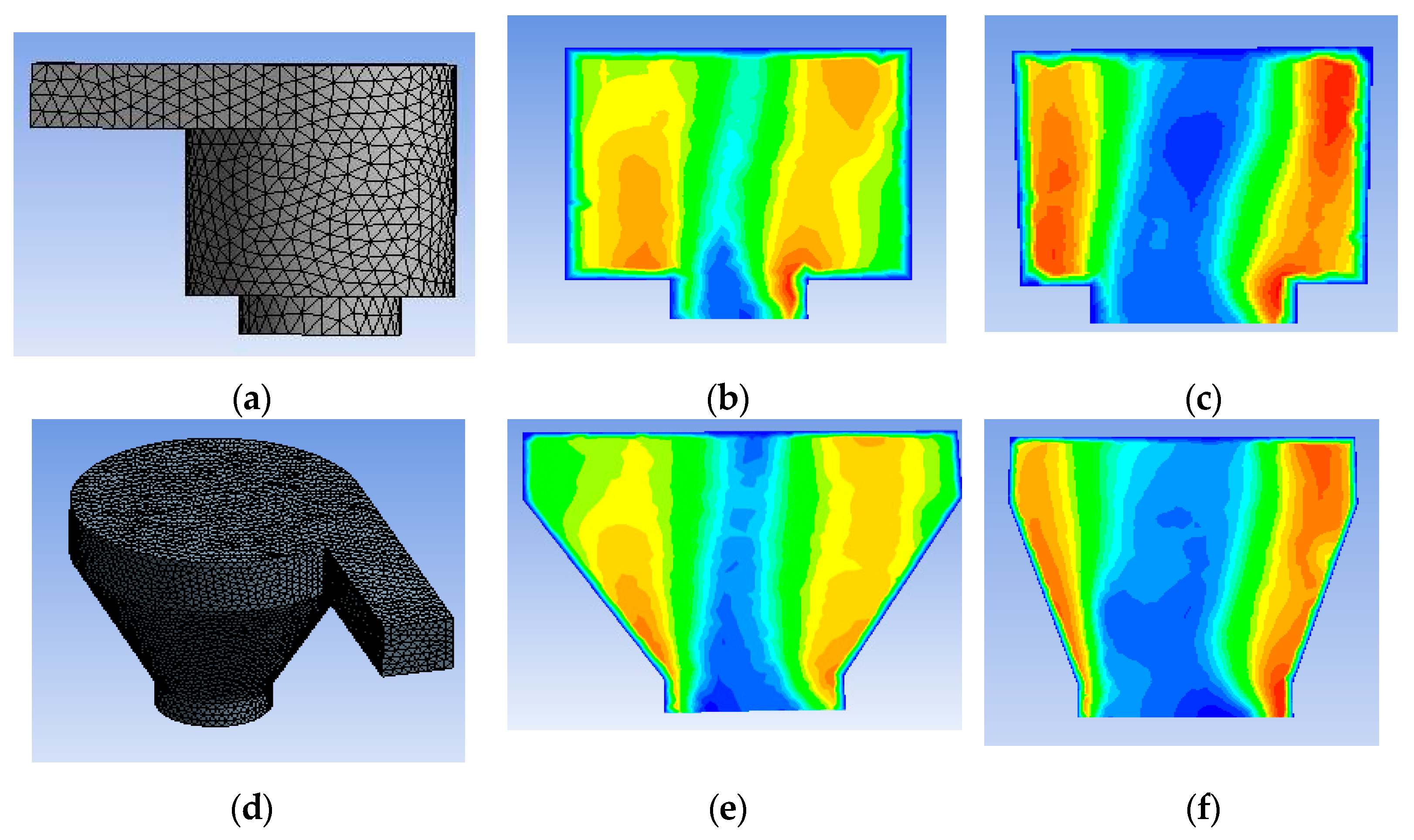
The basin’s vortex symmetry and velocity distribution were studied as shown in Figure 2.
In model 1, the maximum outlet flow velocity 4.907 m/s was achieved when the outlet diameter (d) was 400 mm. A vortex pool was generated but it was not perfect. The inlet velocity was 3 m/s and flow was steady with no slip conditions. In model 2, the outlet diameter (d) was 500 mm, a vortex pool was generated but the outlet velocity was only 3.93 m/s. In model 2, the maximum outlet flow velocity 6.74 m/s was achieved when the outlet diameter (d) was 400 mm. A vortex pool was generated in the center of the basin. Result of both the models are given in Table 1 and Table 2. The pressure decreased because the velocity of the vortex pool increased gradually in the center. The inlet velocity was 3 m/s and the flow was steady with no slip conditions. Therefore, the conical basin with 400 mm outlet diameter (d) was selected for more analysis.

3. Experimental Setup

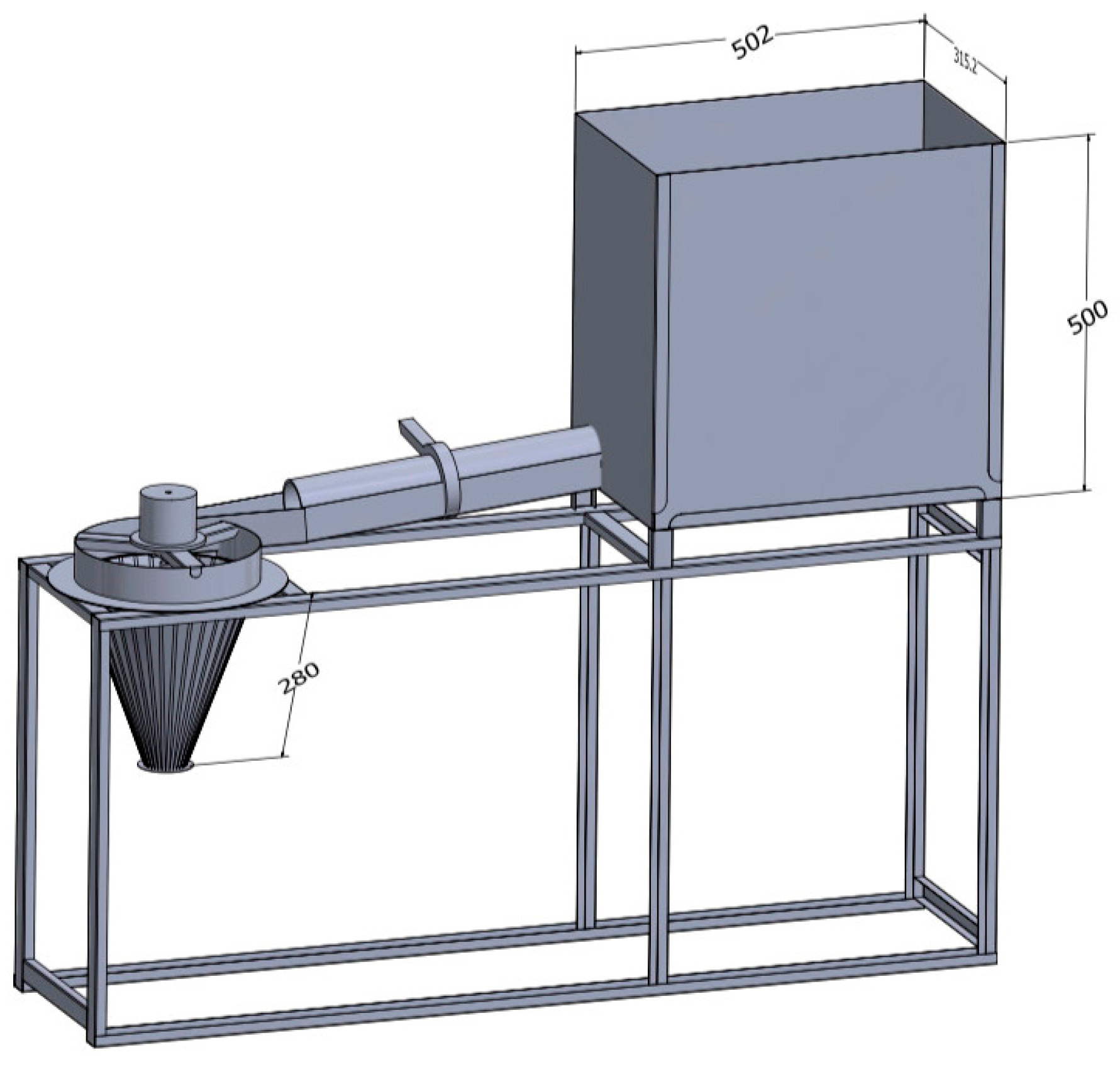
With CFD research, a design was found that maximized the pressure drop and created a full vortex of water, which could be used to generate mechanical power from water. The water entered the basin tangentially, providing the necessary circulation force to generate a vortex. The flow of water in our system is shown in Figure 3. To create a full vortex, it was sucked from its reservoir and sent to the turbine in the inflow channel. Water was recollected in the reservoir after being used to drive the turbine blades. Because we did not have a source of flowing water like a cannel in the lab, we changed the arrangement to make it workable. Water was circulated through a channel using a pump and reservoir. Complete assembly of the apparatus is shown in Figure 3.

4. Result and Discussion

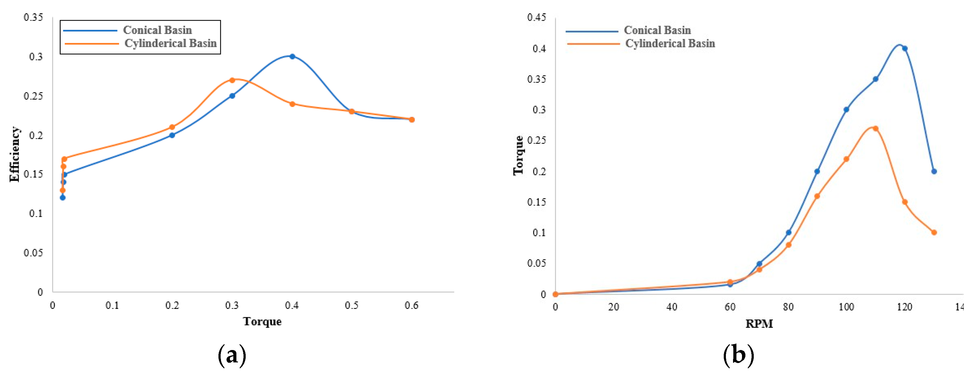
Both torque and efficiency had a direct relation until 0.4 Nm and 0.27 Nm for the conical and cylindrical basin, respectively, and beyond these specific values the efficiency started decreasing for both basins as shown in the graph below.
The RPM of the shaft and torque had direct relation for a particular limit; after this the torque and rpm showed an inverse relation for both the conical and cylindrical basin. The conical basin had a maximum average torque of 0.4 Nm at 120 rpm and after 120 rpm it started decreasing. Similarly, for the cylindrical basin the maximum average value of torque was recorded as 0.27 N-m at 110 rpm and after 110 rpm it started decreasing; both basins had the same relationship between RPM and torque but the conical basin had a maximum average value as compared to the cylindrical basin as shown in Figure 4a,b.

5. Conclusions

With the GWVPP, a low-head power plant, you could produce a lot of energy quickly. This conclusion showed that with a notch angle of 30° and a basin diameter of 1000 mm, the maximum velocity having a value of 6.74 m/sec was given by D/d of 2.5 and an increase in the tangential velocity of the flow or mass flow rate into the basin which raised the water level. When a complete air core was produced, the increase in velocity in the vortex was at its highest point, because the creation of an air core was dependent on a variety of other circumstances; it was impossible to connect the two variables directly. In order to create an air core, the diameter of the exit may be increased while all the other parameters are kept the same. The water level in the basin rose somewhat as the basin diameter was lowered.

Author Contributions

Conceptualization, U.Z. and W.J.; methodology, F.J. and S.A.; software, S.I. and S.A.; validation, W.J., U.Z., F.J., S.A. and S.I.; formal analysis, A.A. and T.M.; investigation, W.J., F.J. and U.Z.; resources, U.Z. and S.A.; data curation, S.I., T.M. and A.A.; writing—original draft preparation, S.I., W.J., F.J. and U.Z.; writing—review and editing, S.I., W.J., F.J. and U.Z.; visualization, U.Z. and W.J.; supervision, W.J. and F.J.; project administration, F.J. All authors have read and agreed to the published version of the manuscript.

Funding

This research received no external funding.

Institutional Review Board Statement

Not applicable.

Informed Consent Statement

Not applicable.

Data Availability Statement

Data are contained within the article.

Acknowledgments

All the authors are grateful to MED, WEC, University of Wah for their kind support of this research.

Conflicts of Interest

The authors confirm that there are no conflicts of interest.

References

  1. Dhakal, R.; Chaulagain, R.K.; Bajracharya, T.; Shrestha, S. Economic Feasibility Study of Gravitational Water Vortex Power Plant for the Rural Electrification of Low Head Region of Nepal and Its Comparative Study with Other Low Head Power Plant. In Proceedings of the 11th International Conference ASIAN Community Knowledge Networks for the Economy, Society, Culture, and Environmental Stability, Kathmandu, Nepal, 30 March–3 April 2015. [Google Scholar]
  2. Date, A.; Akbarzadeh, A. Design and cost analysis of low head simple reaction hydro turbine for Remote Area Power Supply. J. Renew. Energy 2009, 34, 409–415. [Google Scholar] [CrossRef]
  3. Arantes, C.C.; Fitzgerald, D.B.; Hoeinghaus, D.J.; Winemiller, K.O. Impacts of hydroelectric dams on fishes and fisheries in tropical rivers through the lens of functional traits. Curr. Opin. Environ. Sustain. 2019, 37, 28–40. [Google Scholar] [CrossRef]
  4. Sopian, K.; Ali, B.; Asim, N. Strategies for renewable energy applications in the Organization of Islamic Conference (OIC) countries. Renew. Renew. Sustain. Energy Rev. 2011, 15, 4706–4725. [Google Scholar] [CrossRef]
  5. Rahman, M.M.; Tan, J.H.; Fadzlita, M.T.; Muzammil, A.W.K. A review on the development of gravitational water vortex power plant as alternative renewable energy resources. In Proceedings of the International Conference on Materials Technology and Energy, Curtin University, Miri, Malaysia, 20–21 April 2017. [Google Scholar]
  6. Dhakal, S.; Nakarmi, S.; Pun, P.; Thapa, A.B.; Bajracharya, T.R. Development and testing of runner and conical basin for Gravitational Water Vortex Power Plant. J. Eng. Educ. 2014, 10, 140–148. [Google Scholar] [CrossRef]
  7. Power, C.; McNabola, A.; Coughlan, P. A parametric experimental investigation of the operating conditions of gravitational vortex hydropower (GVHP). J. Clean Energy Technol. 2015, 4, 112–119. [Google Scholar] [CrossRef]
  8. Zotlöterer, Smart Energy Systems. Available online: http://www.zotloeterer.com/welcome/gravitation-water-vortex-power-plants/zotloeterer-turbine/ (accessed on 13 September 2023).
  9. Wanchat, S.; Suntivarkon, R. Preliminary design of a vortex pool for electrical generation. Adv. Sci. Lett. 2012, 13, 173–177. [Google Scholar] [CrossRef]
  10. Paish, O. Small hydro power: Technology and current status. Renew. Sustain. Energy Rev. 2002, 6, 537–556. [Google Scholar] [CrossRef]
  11. Ali, M.H. Experimental comparison study for Savonius wind turbine of two & three blades at low wind speed. Int. J. Sci. Eng. 2013, 3, 2978–2986. [Google Scholar]
  12. Nishi, Y.; Inagaki, T. Performance and flow field of a gravitation vortex type water turbine. Int. J. Rotating Mach. 2017, 2017, 2610508. [Google Scholar] [CrossRef]
  13. Shabara, H.M.; Yaakob, O.B.; Ahmed, Y.M.; Elbatran, A.H. CFD simulation of water gravitation vortex pool flow for mini hydropower plants. J. Teknol. 2015, 74, 77–78. [Google Scholar] [CrossRef]
  14. Gheorghe-Marius, M.; Tudor, S. Energy capture in the gravitational vortex water flow. J. Mar. Technol. Environ. 2013, 1, 89. [Google Scholar]
  15. Kueh, T.C.; Beh, S.L.; Ooi, Y.S.; Rilling, D.G. Experimental study to the influences of rotational speed and blade shape on water vortex turbine performance. J. Phys. Conf. Ser. 2017, 822, 012066. [Google Scholar] [CrossRef]
  16. Wanchat, S.; Suntivarakorn, R.; Wanchat, S.; Tonmit, K.; Kayanyiem, P. A parametric study of a gravitation vortex power plant. Adv. Mater. Res. 2013, 805–806, 811–817. [Google Scholar] [CrossRef]
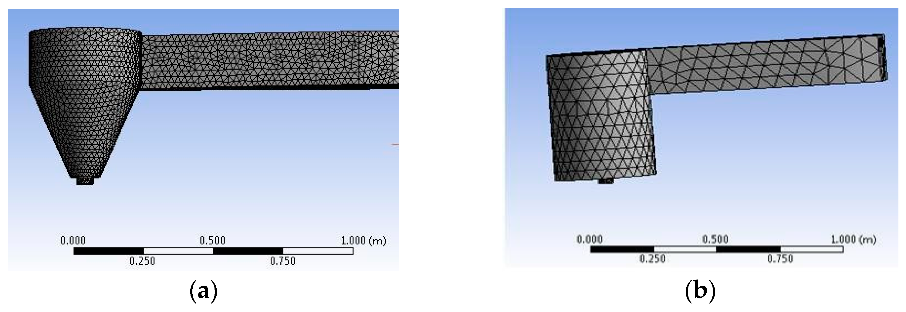
Figure 1. (a) conical basin; (b) cylindrical basin.
Materproc 17 00030 g001
Figure 2. (a) Meshed cylindrical basin model; (b,c) Vortex pool of cylindrical basin; (d) Meshed conical basin model; (e,f) Vortex pool of conical basin.
Materproc 17 00030 g002
Figure 3. Apparatus setup with different basins.
Materproc 17 00030 g003
Figure 4. (a) Relationship between efficiency and torque of the conical and cylindrical basin. (b) Relationship between RPM and torque of conical and cylindrical basin.
Materproc 17 00030 g004
Table 1. Cylindrical models result.
ModelsElementsNodesBasin Diameter (mm)Outlet Diameter (mm)Height (mm)Outlet Flow Velocity
(m/s)
124440476210004009004.907
225083487410005009003.99
324805483810006009004.37
Table 2. Conical models result.
ModelsElementsNodesBasin Diameter (mm)Outlet Diameter (mm)Height (mm)Outlet Flow Velocity
(m/s)
1866081725010004009006.74
2917071790910005009003.93
3969441889110006009004.43
Disclaimer/Publisher’s Note: The statements, opinions and data contained in all publications are solely those of the individual author(s) and contributor(s) and not of MDPI and/or the editor(s). MDPI and/or the editor(s) disclaim responsibility for any injury to people or property resulting from any ideas, methods, instructions or products referred to in the content.