Abstract
Structural Health Monitoring (SHM) of composite systems is challenging due to multiple factors unique to composites. Early detection of any defects in composites is essential to ensure structural integrity and prevent catastrophic failure. In this work, a square Open Loop Resonator (OLR) sensor is proposed for the evaluation of cracks in composite structures. Radio frequency characteristics of the newly designed sensors are analyzed, and their efficiency is studied with respect to various crack sizes and orientations. For the present study, early detection of the crack is focused, and cracking is considered to have occurred in the ground plane of the sensor. A band-pass resonator centered at 2.5 GHz is selected for the study. Structural and HFSS simulations are carried out using commercially available software packages. The proposed sensor is found to be effective in early detection of the cracks and is a viable choice for structural health monitoring applications.
1. Introduction
Structural parts subjected to high loads and other harsh operating environments can develop cracks in regions with high strain concentration. The timely detection of such defects can help avoid catastrophic failure of the structure. Moreover, such predictive, condition-based maintenance is generally more cost-effective and safer compared to traditional time-based maintenance. While traditional methods for analysis of stress and strain continue to be improved [1], Structural Health Monitoring (SHM) is a rapidly evolving field that requires reliable sensors providing data on multiple structural parameters. There are two major structural factors required to be monitored by an SHM system: strains and cracks. Detection of strain concentrations and crack initiation can provide sufficient warnings regarding the health of the structure. Thus, it is essential to have sensors which can accurately detect the formation and propagation of such cracks in the structure being monitored.
Typically, wired sensors such as strain gauges, fiber Bragg grating sensors, piezoelectric and eddy current sensors, among others, are used for SHM [2,3]. Novel contact-based methods utilizing nano sensing sheets [4] have also been explored.
Wireless Radio Frequency (RF) sensors have received much attention lately for applications in SHM [5]. Wireless systems have the advantage of being compact enough for embedded applications, with passive sensors eliminating the constraint of requiring a power source. This leads to a sensor which can be embedded with minimal intrusion in the structure. The advantages of wireless sensors have led to their use in multidisciplinary SHM techniques, such as combining vibration analysis of structures using wireless sensors, incorporation of novel geometries like auxetic structures [6], and image processing [7].
Microstrip patch antennas are the most common RF devices used for strain and crack detection. The first attempts to use such antennas for strain sensing was in 2008 [8]. Various means have been adopted to increase the sensitivity and compactness of the sensor. A multidirectional strain sensor which can be used for damage detection using meandered patch designs has been studied [9]. Frequency doubling techniques have also been applied by the addition of stubs in order to increase the usability of microstrip patches for strain sensing [10]. Attempts have been made to quantify and classify cracks using passive RFID patches based on changes in their frequency responses [11]. The issue of degrading communication with an increase in crack width has been addressed by harnessing parametric design methods for RFID sensors [12]. Change in the dielectric constant of substrate material when strain is applied has been studied in order to increase accuracy [13]. Various types of geometries for patches have also been considered, with circular patch antennas with rectangular windows demonstrating capability to find cracks [14]. RFID tags based on microstrip patches capable of being accurately sensitive to changes in depth of crack have been studied recently [15].
Microstrip patch antennas have thus gained traction in research for both strain sensing and crack detection. Moreover, resonators are often utilized in chipless RFID applications alongside patch antennas for encoding purposes. Passive RFID tags with multiple complementary spiral resonators capable of object tracking have been studied, with additional spirals proven to provide better range and security at the same operating frequency [16]. Circular microstrip patch antennas using four top-loaded dipole resonators were able to create a tag that can detect sub-millimeter cracks [17]. Cylindrical dielectric resonators have been used directly to detect cracks that are 2 mm wide with frequency shift of about 25.4 MHz/mm [18]. Chipless RFID tags of complementary spiral structure design and incorporating up to eight resonators have been developed which has usability in monitoring and sensing applications. The tag operates in the L band and has eight-bit encoding [19].
Resonators have thus been used alongside microstrip patch antennas in RFID tags for encoding purposes. However, the potential to utilize planar resonators as crack detection sensors has not been investigated in detail. Compared to a square closed loop resonator with the same dimensions, an open loop counterpart can resonate at half the frequency. In this work, a square Open Loop Resonator (OLR) has been chosen due to its compact size as well as ease of design [20].
2. Design of Resonator
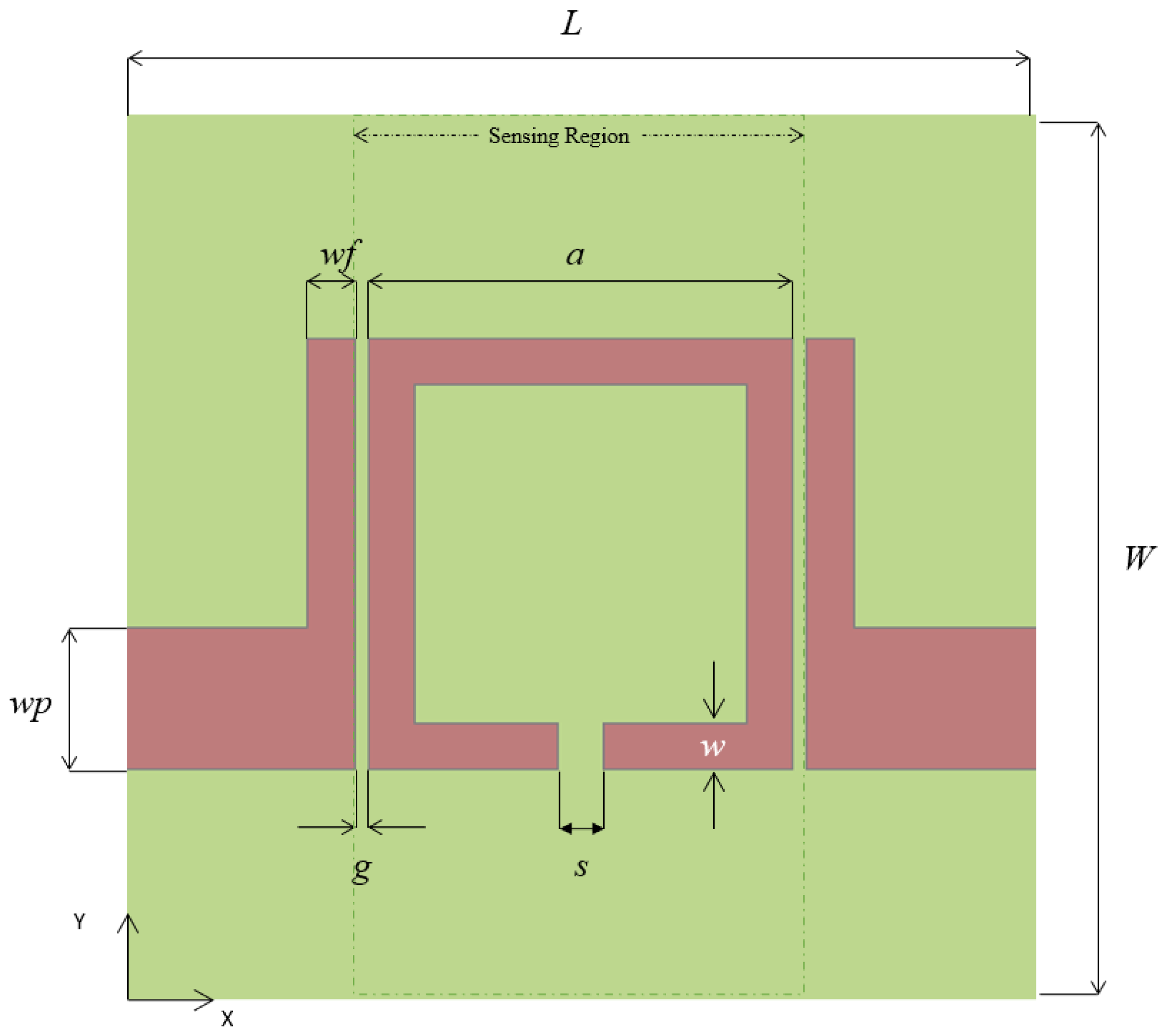
The geometry of the square Open Loop Resonator is shown in Figure 1. The substrate material chosen is FR-4, which has a dielectric constant of 4.4 and thickness of 1.6 mm. The fundamental resonance frequency f of the square Open Loop Resonator is obtained by:
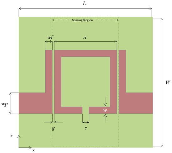
Figure 1.
Geometry of the square OLR.
In Equation (1), c is the speed of light, p is the average perimeter of square loop, s is the distance between the open ends and εeff is the effective permittivity of the substrate. The change in effective dielectric constant due to presence of a crack, measured in terms of consequent shift in frequency f, is proposed for crack detection in composite structures.
The square Open Loop Resonator is designed for 2.5 GHz and the resonator characteristics are simulated using ANSYS HFSS 2023 R2. The design characteristics of the resonator are provided in Table 1. It must be noted that the outer dimensions of the ground plane are similar to that of the substrate. The dielectric substrate is considered to be made of FR-4 with copper-clad resonator components.

Table 1.
Dimensions of square OLR.
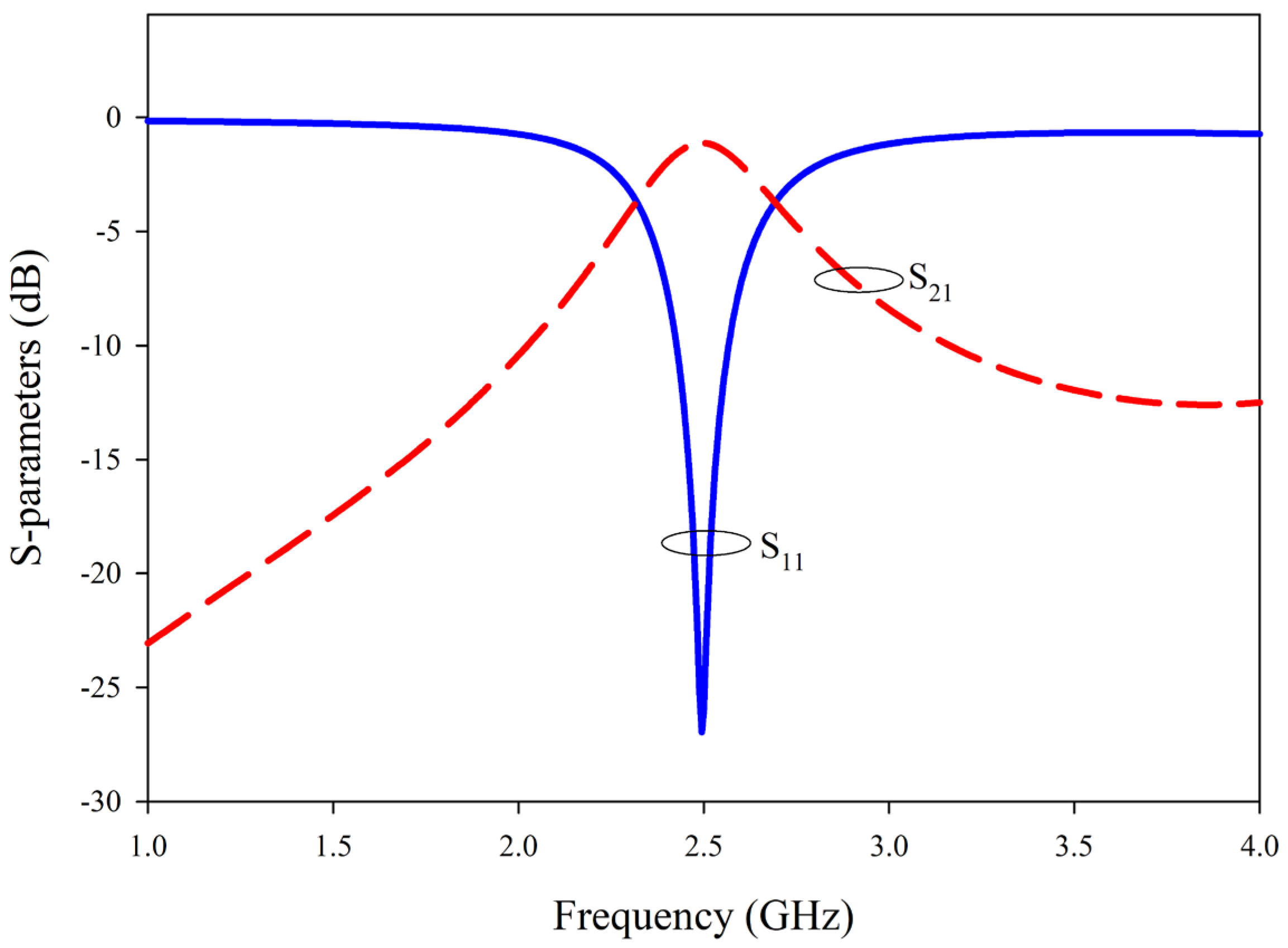
The performance of the resonator is analyzed from 1 to 4 GHz. The reflection and transmission characteristics of the resonator are provided in Figure 2. The resonator proves to be a band-pass device with a bandwidth of 372 MHz.
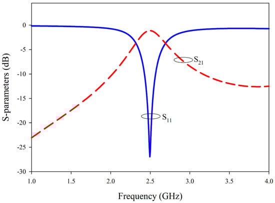
Figure 2.
Variation in S-parameters with frequency of the square OLR.
3. Results and Discussion
In this work, two different crack alignments are studied, with the width of crack as 0.2 mm, which is an acceptable crack width for reinforced concrete [21]. In the analysis, the early stage of crack formation and propagation is analyzed, thus restricting the study along the ground plane alone.
3.1. Crack Along the Length of the Resonator
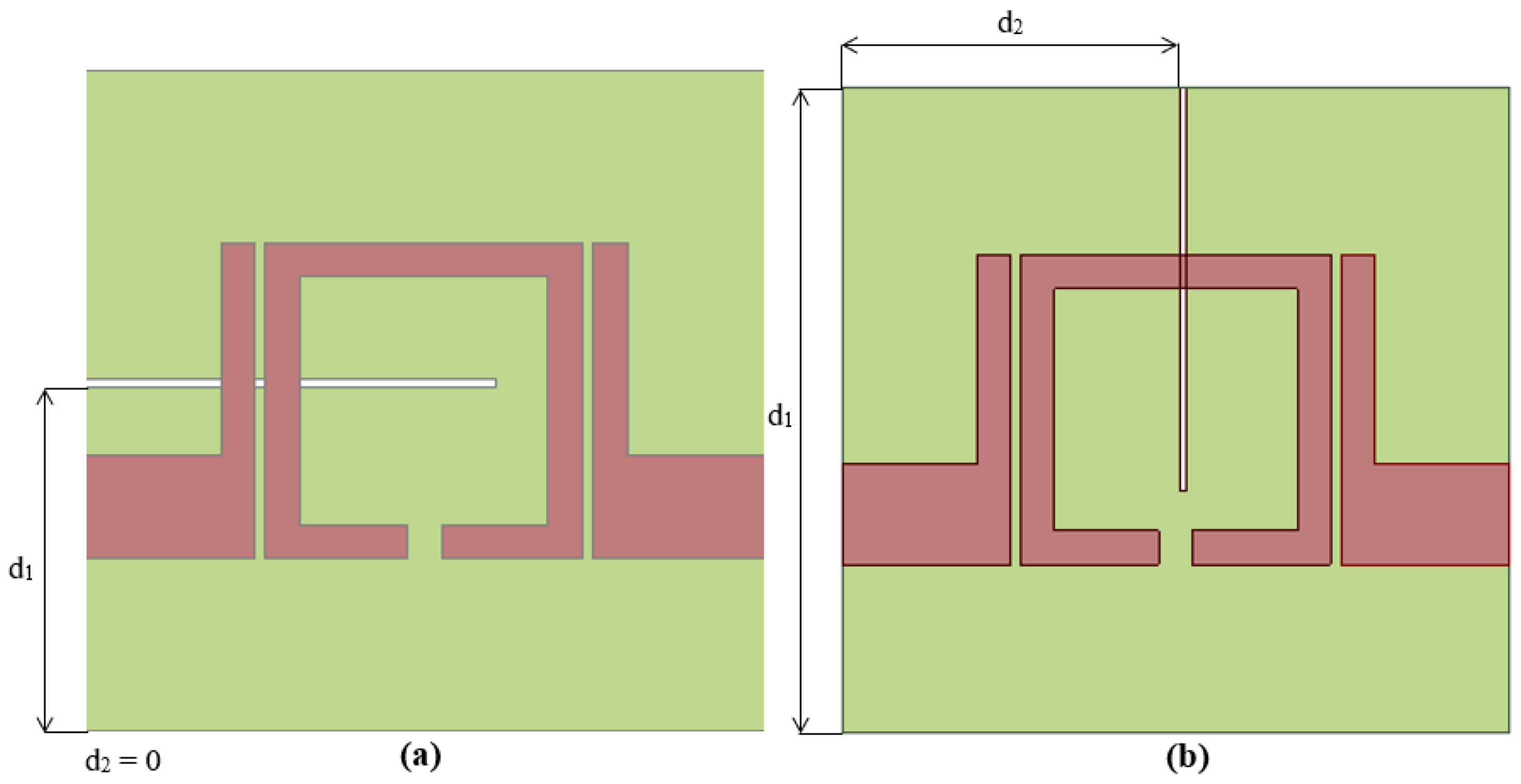
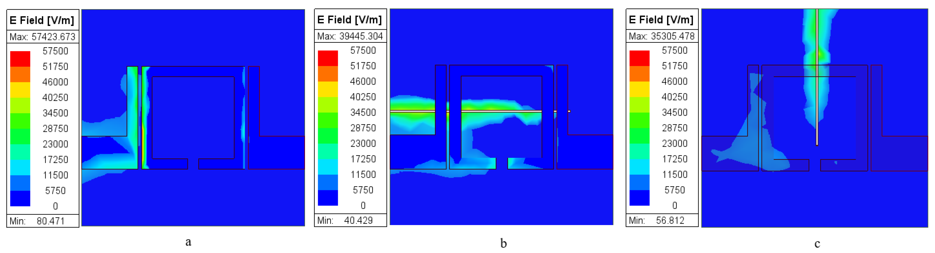
The origin of the crack is assumed to be located at a distance d1 = 10 mm along the Y axis with location along X axis being at d2 = 0, as seen in Figure 3a. In the initial analysis, the length of crack is increased along the X- axis with the length increasing from 4 mm to 18 mm going through the sensor, thus perturbing the field distribution relative to the uncracked sensor, as seen in Figure 4a,b, which also changes the resonant frequency of the sensor.
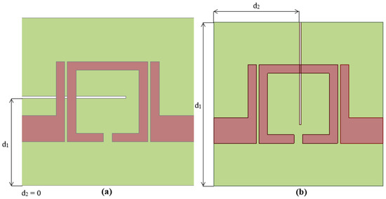
Figure 3.
(a) Crack along the length of the resonator (b) Crack along the width of the resonator.
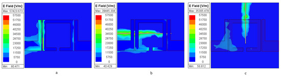
Figure 4.
Electric field distribution for with (a) Sensor without crack (b) Sensor with crack along length of sensor (c) Sensor with crack along width of sensor.
A formation of a crack in the sensor means that an environment of air is present instead of the existing dielectric, thus changing the boundary conditions at the interface and thus the effective dielectric constant for the wave propagation. This is clearly seen in the field analysis of the structure with and without a crack in Figure 4.
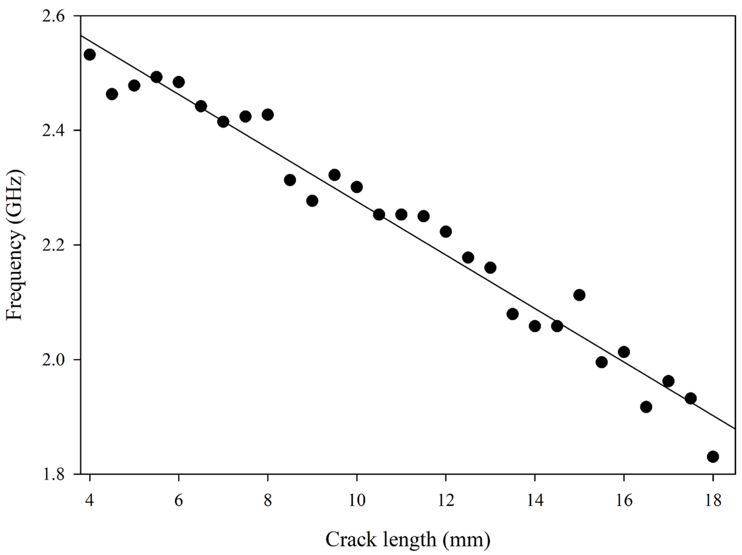
The change in resonant frequency of the sensor is observed in the reflection characteristics as the sensor is a band-pass filter and is depicted in Figure 5.
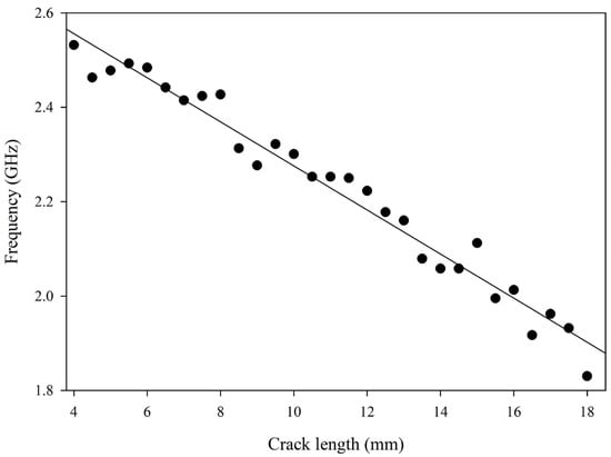
Figure 5.
Resonant frequency shift with increasing crack length along length of the sensor.
The matching and the bandwidth of the resonator deteriorated with crack length over 8 mm. This is due to the disturbances caused to the coupling region along the feed line by the crack, affecting the entire field generated by the sensor.
The response of the sensor is permissible only when the crack encompasses the geometry, i.e., in the sensing region of the sensor. The fields are predominant in this region; thus, any alteration leads to desired sensor response.
The frequency shift is found to be 36 MHz for 1 mm of crack length which provides good sensitivity in identifying and monitoring various crack lengths.
The frequency response at Lc = 2 mm is 2.472 GHz which falls to 1.83 GHz for a crack length of 18 mm. The total drop in frequency from the original design without a crack is thus 664 MHz, which corresponds to a fall in frequency of nearly 36 MHz for every millimeter of crack length.
3.2. Crack Along the Width of the Resonator
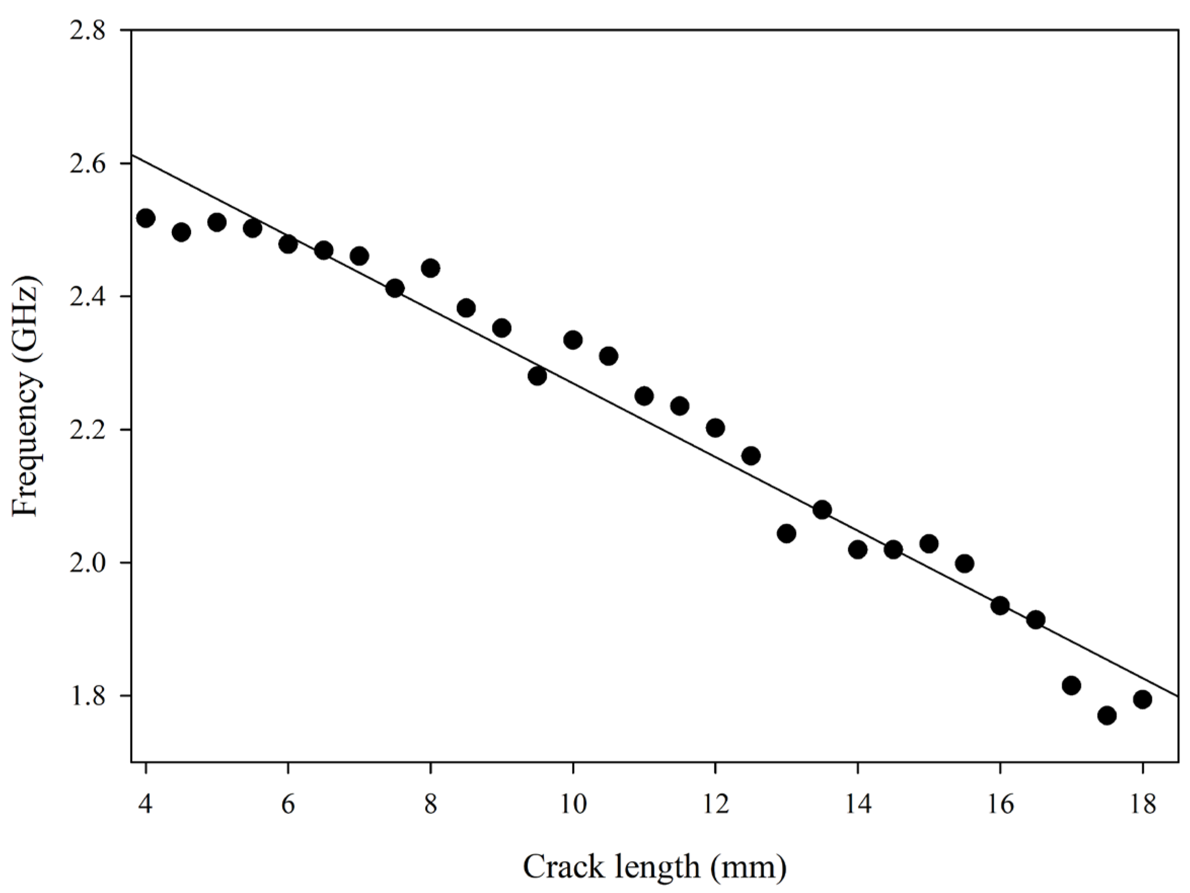
The crack is assumed to be located at d2 = 10 mm along the X axis with d1 = W being the location along the Y axis, as seen in Figure 3b. The crack extends in the Y direction along the width of the sensor. With the same assumptions as considered in Section 3.1, the effect of crack length is analyzed for a 0.2 mm wide crack in the ground plane.
Increase in crack length is observed to perturb the field distribution, as seen in Figure 4a,c. The corresponding reflection characteristics of the sensor are provided in Figure 6.

Figure 6.
Resonant frequency shift with increasing crack length along the width of the crack.
The matching and the bandwidth of the resonator did not deteriorate with crack length in the Y direction thus making OLR an effective sensor for crack detection and monitoring.
The frequency shift is found to be 39 MHz for every 1 mm of crack length which provides good sensitivity in identifying and monitoring crack propagation.
The proposed square OLR has exhibited excellent crack propagation monitoring capability along both axes and is compared with RF sensors in Table 2. The square OLR showcases superior sensitivity to crack length while being more compact and uses an affordable FR4 substrate.
Table 2.
Comparison of square open loop resonator with other popular RF sensors.
4. Conclusions
In general, the presence of a crack creates a perturbation in the ground plane. This changes the εeff of the substrate and increasing the size of the crack continues to change effective permittivity, leading to a reduction in frequency.
The design and analysis of a square open loop resonator for crack detection is presented. The primary application of this RF device lies in the field of SHM. Two cracks along the length and width of the resonator are considered. The results obtained show that a primarily linear frequency shift of 36 MHz/mm and 39 MHz/mm occurs for cracks along the length and width of the sensor, respectively. The observable difference in the frequency shifts has the potential to make the differentiation of crack orientation possible. More scenarios can be considered in the future for more clarity regarding initial crack lengths and overall behavior of the resonator.
Author Contributions
Conceptualization, S.K.M. and M.P.H.; methodology, S.K.M.; software, C.B.A. and A.K.M.; validation, A.K.M., S.K.M. and M.P.H.; formal analysis, A.K.M.; investigation, A.K.M. and C.B.A.; resources, S.K.M.; data curation, A.K.M.; writing—original draft preparation, A.K.M.; writing—review and editing, S.K.M. and M.P.H.; visualization, A.K.M. and C.B.A.; supervision, S.K.M. and M.P.H.; project administration, S.K.M. and M.P.H. All authors have read and agreed to the published version of the manuscript.
Funding
This research received no external funding.
Institutional Review Board Statement
Not applicable.
Informed Consent Statement
Not applicable.
Data Availability Statement
The data presented in this study are available upon request from the corresponding author.
Acknowledgments
The authors are deeply grateful to Mata Amritanandamayi Devi, Chancellor of Amrita Vishwa Vidyapeetham, for enlightening us and enabling our research activities.
Conflicts of Interest
The authors declare no conflicts of interest.
References
- Kumar, P.; Hariprasad, M.P.; Menon, A.; Ramesh, K. Experimental study of dry stone masonry walls using digital photoelasticity. Strain 2020, 56, e12372. [Google Scholar] [CrossRef]
- Ferreira, P.M.; Machado, M.A.; Carvalho, M.S.; Vidal, C. Embedded Sensors for Structural Health Monitoring: Methodologies and Applications Review. Sensors 2022, 22, 8320. [Google Scholar] [CrossRef] [PubMed]
- Dolbachian, L.; Harizi, W.; Aboura, Z. Structural Health Monitoring (SHM) Study of Polymer Matrix Composite (PMC) Materials Using Nonlinear Vibration Methods Based on Embedded Piezoelectric Transducers. Sensors 2023, 23, 3677. [Google Scholar] [CrossRef] [PubMed]
- Nisha, M.S.; Venthan, S.M.; Rangasamy, G.; Sam, D.P.; Akilesh, G.; Bhaskar, D.S. Fabrication and testing of rGO PVDF nano sensing sheets on Glass Fiber Reinforced Polymer for Structural Health Monitoring in aerospace. Appl. Nanosci. 2023, 13, 5935–5947. [Google Scholar] [CrossRef]
- Zhang, J.; Tian, G.Y.; Marindra, A.M.J.; Sunny, A.I.; Zhao, A.B. A Review of Passive RFID Tag Antenna-Based Sensors and Systems for Structural Health Monitoring Applications. Sensors 2017, 17, 265. [Google Scholar] [CrossRef] [PubMed]
- Praveen, A.P.; Menon, S.K.; Babu, J.S.; Donelli, M.; Hariprasad, M.P. An auxetic based geometric tuning approach in microwave sensors for enhanced sensitivity in strain measurements. Measurement 2025, 253, 117826. [Google Scholar] [CrossRef]
- Harinath Reddy, C.; Mini, K.M.; Radhika, N. Structural Health Monitoring—An Integrated Approach for Vibration Analysis with Wireless Sensors 4 to Steel Structure Using Image Processing. In Proceedings of the International Conference on ISMAC in Computational Vision and Bio-Engineering 2018 (ISMAC-CVB), Palladam, India, 16–17 May 2018; Springer International Publishing: Berlin/Heidelberg, Germany, 2018; pp. 1595–1610. [Google Scholar] [CrossRef]
- Tata, U.; Huang, H.; Carter, R.; Chiao, J. Exploiting a patch antenna for strain measurements. Meas. Sci. Technol. 2008, 20, 015201. [Google Scholar] [CrossRef]
- Daliri, A.; Wang, C.H.; John, S.; Galehdar, A.; Rowe, W.S.T.; Ghorbani, K. Multidirectional Circular Microstrip Patch Antenna Strain Sensor. In Proceedings of the ASME 2011 Conference on Smart Materials, Adaptive Structures and Intelligent Systems, Scottsdale, AZ, USA, 18–21 September 2011; Volume 2, pp. 481–487. [Google Scholar] [CrossRef]
- Song, G.; Zhang, B.; Lyu, Y.; Sun, T.; Wang, X.; He, C. Application of frequency doubling in micro-strip patch antenna for wireless strain detection. Sens. Actuators A Phys. 2021, 21, 112403. [Google Scholar] [CrossRef]
- Zhang, J.; Tian, G.Y.; Zhao, A.B. Passive RFID sensor systems for crack detection & characterization. NDT E Int. 2017, 86, 89–99. [Google Scholar] [CrossRef]
- Caizzone, S.; DiGiampaolo, E. Wireless Passive RFID Crack Width Sensor for Structural Health Monitoring. IEEE Sens. J. 2015, 15, 6767–6774. [Google Scholar] [CrossRef]
- Yi, X.; Wu, T.; Wang, Y.; Tentzeris, M.M. Sensitivity Modeling of an RFID-Based Strain Sensing Antenna with Dielectric Constant Change. IEEE Sens. J. 2015, 15, 6147–6155. [Google Scholar] [CrossRef]
- Zhang, J.; Huang, B.; Zhang, G.; Tian, G.Y. Wireless Passive Ultra High Frequency RFID Antenna Sensor for Surface Crack Monitoring and Quantitative Analysis. Sensors 2018, 18, 2130. [Google Scholar] [CrossRef] [PubMed]
- Zhang, B.; Lyu, Y.; Lee, Y.C. Passive wireless strain and crack sensing using a RFID-based patch antenna. J. Phys. Conf. Ser. 2022, 2198, 012018. [Google Scholar] [CrossRef]
- Aiswarya, S.; Ranjith, M.; Menon, S.K. Passive RFID tag with multiple resonators for object tracking. In Proceedings of the 2017 Progress in Electromagnetics Research Symposium—Fall (PIERS—FALL), Singapore, 19–22 November 2017; pp. 742–746. [Google Scholar]
- Marindra, A.M.J.; Tian, G.Y. Chipless RFID Sensor Tag for Metal Crack Detection and Characterization. IEEE Trans. Microw. Theory Tech. 2018, 66, 2452–2462. [Google Scholar] [CrossRef]
- Zhang, J.; Huang, H.; Huang, C.; Zhang, B.; Li, Y.; Wang, K.; Su, D.; Tian, G.Y. A Configurable Dielectric Resonator Based Passive Wireless Sensor for Crack Monitoring. IEEE Trans. Antennas Propag. 2019, 67, 5746–5749. [Google Scholar] [CrossRef]
- Menon, S.K.; Donelli, M. Development of Enhanced Range, High Q, Passive, Chipless RFID Tags for Continuous Monitoring and Sensing Applications. Electronics 2022, 11, 127. [Google Scholar] [CrossRef]
- Astuti, D.W.; Juwanto, J.; Alaydrus, M. A bandpass filter based on square open loop resonators at 2.45 GHz. In Proceedings of the 2013 3rd International Conference on Instrumentation, Communications, Information Technology and Biomedical Engineering (ICICI-BME), Bandung, Indonesia, 7–8 November 2013; pp. 147–151. [Google Scholar] [CrossRef]
- Rasidi, N.; Agoes Soehardjono, M.D.; Zacoeb, A. Prediction of Crack Width in Panel Composite Deck Slab Under Repeated Loading. Aust. J. Basic Appl. Sci. 2013, 7, 112–118. [Google Scholar]
- Mohammad, I.; Huang, H. Monitoring fatigue crack growth and opening using antenna sensors. Smart Mater. Struct. 2013, 19, 055023. [Google Scholar] [CrossRef]
- Mohammad, I.; Huang, H. An antenna sensor for crack detection and monitoring. Adv. Struct. Eng. 2011, 14, 47–53. [Google Scholar] [CrossRef]
- Li, X.; Xue, S.; Xie, L.; Wan, G. A miniaturized passive wireless patch antenna sensor for structural crack sensing. Struct. Health Monit. 2024, 23, 3276–3295. [Google Scholar] [CrossRef]
Disclaimer/Publisher’s Note: The statements, opinions and data contained in all publications are solely those of the individual author(s) and contributor(s) and not of MDPI and/or the editor(s). MDPI and/or the editor(s) disclaim responsibility for any injury to people or property resulting from any ideas, methods, instructions or products referred to in the content. |
© 2025 by the authors. Licensee MDPI, Basel, Switzerland. This article is an open access article distributed under the terms and conditions of the Creative Commons Attribution (CC BY) license (https://creativecommons.org/licenses/by/4.0/).