Abstract
LED lighting plays a pivotal role in the illumination landscape owing to its substantial energy efficiency, prolonged operational lifespan, environmental advantages, superior light quality, and its capacity for advanced lighting control. Flicker in led lighting systems has emerged as a substantial concern and is appropriate to its potential opposing impacts on human health and visual comfort. Hence, this paper presents a comprehensive analysis, design, and mitigation strategy for flicker in a DC-DC led driver that incorporates a valley fill circuit. The initial stage of this investigation involves an analysis of a conventional cuk converter. However, it is noted that this converter produces an inverting output and experiences high current stress on the semiconductor switch. Consequently, to address these limitations, a non-inverting cuk converter (NICC) is introduced, resulting in a positive output, reduced voltage and current ripple and increased efficiency. To surmount these challenges, the implementation of a valley fill circuit is proposed. This addition facilitates the rapid attainment of a steady state, increases efficiency, and substantially reduces the output voltage and current ripple. An in-depth analysis of the stress imposed on the switch is conducted, leading to the development of a circuit designed to extend the operational life of the LED driver. Therefore, this paper compares the topologies of three different DC-DC cuk power converters. These converters include conventional cuk, non-inverting cuk (NICC), and non-inverting cuk with valley-fill. The performance metrics are examined and compared for all three topologies. The findings of this study affirm that the proposed driver circuit is highly effective in mitigating flicker, thereby enhancing the user experience and elevating the quality of led lighting, all while maintaining energy efficiency. The MATLAB simulations of these converters are performed to validate the theoretical results.
1. Introduction
LED lighting has established itself as a pivotal player in the field of illumination, thanks to its numerous advantages. Notably, LEDs, or light emitting diodes, stand out for their exceptional energy efficiency, converting a higher percentage of energy into light when compared to traditional bulbs that often dissipate heat energy. This efficiency turns into substantial energy reserves and reduces electricity bills. For residential lighting, LEDs are widely embraced due to their energy efficiency and extended lifespan. They offer bright, warm light and come in various color temperatures, allowing homeowners to tailor the ambiance of their living spaces. In commercial spaces like offices, retail stores, and warehouses, LEDs are preferred for their energy efficiency and long lifespan. Their directional lighting capability proves advantageous in highlighting specific areas or products. Additionally, LEDs seamlessly integrate into smart lighting systems, enhancing control and automation. In street lighting, LEDs are commonly employed owing to their energy efficiency, durability, and directional lighting properties. They contribute to better visibility while minimizing light pollution compared to traditional streetlights. The prolonged lifespan of LEDs also translates into reduced maintenance costs for municipalities. Automotive lighting relies on LEDs due to their compact size, energy efficiency, and rapid response time. They are commonly utilized in headlights, brake lights, turn signals, and interior lighting, enhancing road safety through quick illumination and low power consumption. Within industrial settings, LEDs are preferred for their capacity to deliver focused and intense illumination. Their resistance to vibrations and impact makes them well-suited for harsh environments, and their extended lifespan reduces the need for frequent replacements in industrial facilities [1,2,3].
Despite the widespread applications of lighting, the occurrence of flickering in LED lighting systems has become a notable concern, given its potential adverse effects on human health and visual comfort. This concern is exacerbated by several factors. Firstly, lighting systems are particularly sensitive to variations in power supply, arising from fluctuations in voltage or current. Any inconsistency in the power supply can result in fluctuations in light output, thereby causing noticeable flicker. Another contributing factor is the low frequency of AC power in certain regions, such as those with a 50 Hz power frequency. In such cases, the human eye is more susceptible to perceiving flicker, particularly when the LED driver or control system lacks effective mitigation measures. Additionally, the driver circuit within LED systems may exhibit voltage ripple, especially in specific converter topologies. This ripple effect can lead to variations in light output, further contributing to the perceptibility of flicker. These factors underscore the need for addressing flicker issues in LED lighting systems to ensure optimal visual experiences and safeguard human well-being [4,5,6].
Hence, this report presents a comprehensive analysis, design, and mitigation strategy for flickering in a DC-DC LED driver that incorporates a valley fill circuit. The initial stage of this investigation involves an analysis of a conventional cuk converter. The conventional cuk converter is designed with the source voltage of 12 V and a duty cycle of 67% and with a switching frequency of 30 kHz. It is noted that this converter produces an inverting output and experiences high current stress on the semiconductor switch. Consequently, to address these limitations, a NICC is introduced, resulting in a positive output and increased efficiency. Nevertheless, it is observed that a transient period occurs before reaching a steady state, with significant current and voltage ripple evident. To summarize these challenges, the implementation of a valley fill circuit is proposed [7,8,9]. This addition facilitates the rapid attainment of a steady state, increases efficiency, and substantially reduces the LED voltage and current ripple.
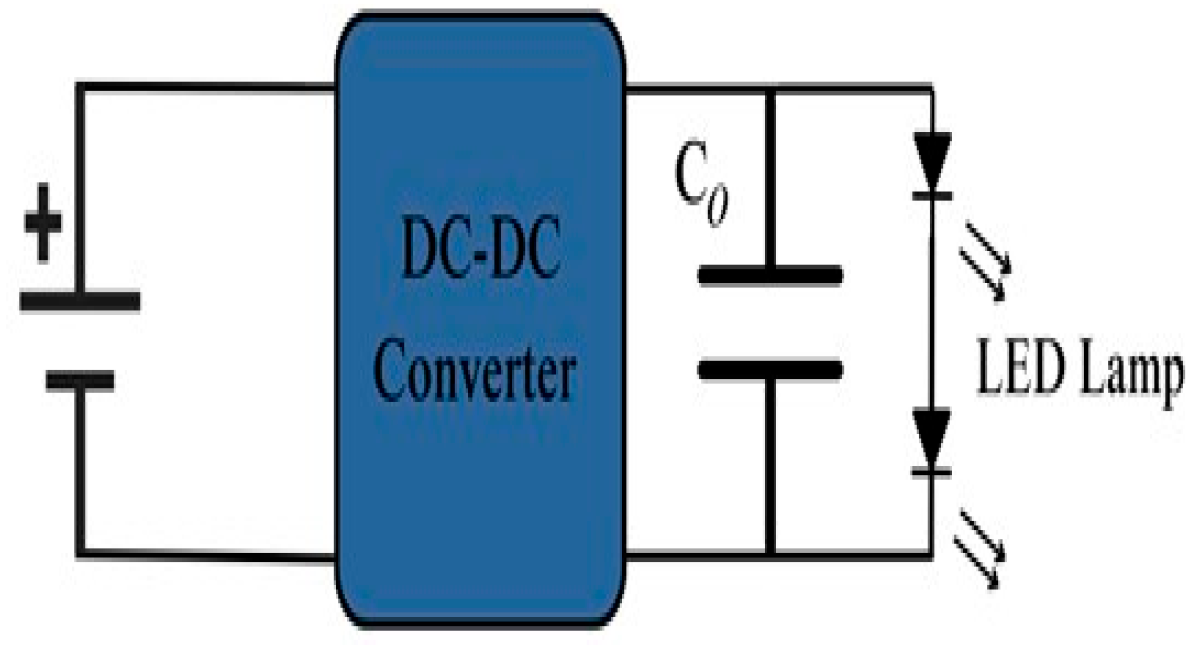
Furthermore, an innovative topology is introduced to minimize ripple to the lowest achievable levels while concurrently enhancing efficiency. An in-depth analysis of the stress imposed on the switch is conducted, leading to the development of a circuit designed to extend the operational life of the LED driver. Therefore, this research work proposes a novel Non-inverting DC-DC cuk [10,11,12] converter (NICC) with valley-fill circuit for LED applications and the block diagram of this proposed converter is depicted in Figure 1. The valley-fill circuit is used to improve efficiency, reduce switch current and voltage stress, and reduce load current ripple and voltage ripple, [13,14,15,16]; among these, other performance metrics are also examined. Then, the proposed converter is compared with two different existing DC-DC cuk power converter topologies. These converters include conventional cuk and non-inverting cuk. The findings of this research work affirm that the proposed driver circuit is highly effective in mitigating flicker, thereby enhancing the user experience, and elevating the quality of LED lighting, all while maintaining energy efficiency. The MATLAB 2021a simulations of these converters are performed to validate the theoretical results.

Figure 1.
Block Diagram of the proposed work.
2. Proposed Non-Inverting Cuk Converter with Valley Fill Circuit
The NICC with a valley-fill circuit using a single switch is an advanced DC-DC converter that combines the features of a non-inverting cuk topology with a valley-fill circuit. This design is aimed at enhancing the performance of the converter, especially in terms of reducing voltage ripple and ensuring continuous operation.
A valley-fill circuit, classified as a passive power-factor correction setup, employs a basic full-wave diode-bridge rectifier. This specific configuration, known as passive valley-fill circuit, aims to enhance power factor and diminish harmonic distortion within the input line current while simultaneously reducing the overall volume. Implementing this approach can contribute to stabilizing lamp power. The capacitor is arranged in series and discharged through the diodes. The diode’s purpose is to prevent the discharge of capacitor C2 through capacitor C3.
2.1. Working
In the step-down (buck) mode, the closure of the switch (Q1) enables the flow of current via the inductor (L2), storing energy in its magnetic field, while the diode (D1) is reverse-biased, preventing current flow, and concurrently, the valley-fill circuit charges capacitors, storing extra energy in this phase.
In the step-up (boost) mode with valley-fill, the opening of the switch (Q1) in the second phase releases the energy deposited in the inductor, leading to forward-biasing of the diode, facilitating current flow to the load through the diode and capacitor, with the valley-fill circuit aiding in maintaining a smoother voltage across the load. Continuous operation is ensured by the valley-fill circuit, utilizing energy stored during the buck mode to supplement the boost mode, minimizing voltage ripple and enhancing converter stability. Voltage control is achieved by adjusting the switch’s duty cycle, similar to the non-inverting cuk converter, providing precise control over the output voltage. The NICC with a valley-fill circuit is depicted in Figure 2 and it maintains a non-inverting output, aligned with the input voltage polarity, contributing to a more stable output by reducing voltage ripple. The incorporation of the valley-fill circuit significantly improves performance by reducing voltage ripple, ensuring a consistently smooth output voltage, which is particularly advantageous in applications requiring a stable and clean power supply.
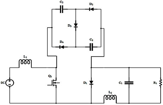
Figure 2.
Circuit Diagram of NICC with valley-fill circuit.
2.2. Design of NICC with Valley-Fill Circuit
The parameters for the inductor, capacitor, and the duty cycle at which it should be operated is derived from the design Equations (1)–(3) and is mentioned in Table 1. The input parameters for the value of duty cycle, inductor, and capacitor for which it should be designed and operated are derived from the below design Equations (1)–(3).

Table 1.
NICC With Valley-Fill Design Parameters.
Duty Cycle
Inductor Value
Capacitance Value
Here D is the duty cycle, Vin is the supply voltage supplied to the converter, Vout is the desired LED voltage of the cuk converter, L is the required inductance value, f is the switching frequency of the converter, Vin is the source voltage supplied to the converter, ΔIL is the desired current ripple in the inductor, C is the output capacitance, and ΔVout is the desired LED voltage ripple.
The parameters for the inductor, capacitor, and the duty cycle at which it should be operated is derived from the design Equations (1)–(3) and is mentioned in Table 1.
The LED current and current ripple, LED voltage and voltage ripple are depicted in Figure 3, Figure 4, Figure 5 and Figure 6, respectively.
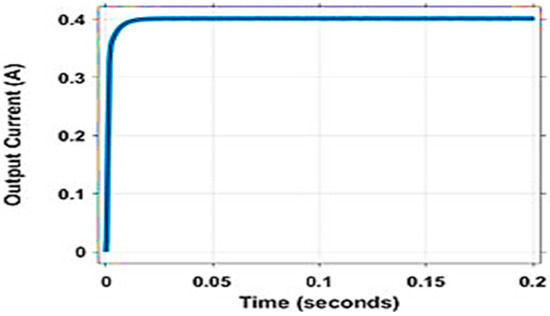
Figure 3.
LED Current of NICC with Valley-Fill Circuit.
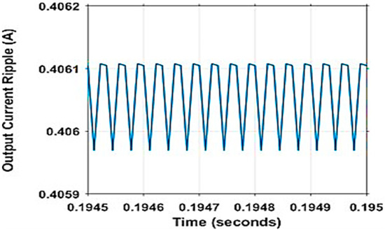
Figure 4.
LED Current Ripple of NICC with Valley-Fill Circuit.
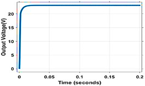
Figure 5.
LED Voltage of NICC with Valley-Fill Circuit.
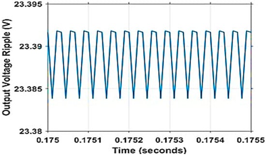
Figure 6.
LED Voltage Ripple of NICC with Valley-Fill Circuit.
From Figure 3, the LED current of the NICC with valley-fill is observed to be 0.3689 A.
From Figure 4, the LED current ripple of the NICC with valley-fill is observed to be 0.017441%.
From Figure 5, the LED voltage of the NICC with valley-fill is observed to be 24.42 V.
From Figure 6, the LED voltage ripple of the NICC with valley-fill is observed to be 0.02162%.
The various performance parameters of the proposed topology are calculated with the help of Equations (4)–(10) and compared with existing topologies.
where
Imax = Maximum Current,
Imin = Minimum Current,
where
Vmax = Maximum Voltage,
Vmin = Minimum Voltage.
- Conduction Loss
- Switching Loss
- Efficiency
- Luminous Efficiency
- Flicker Index
The performance parameters are computed from Equations (4)–(10) and they are shown in Table 2.
Table 2.
Performance Parameters of NICC With Valley-Fill Circuit.
Once the circuit is designed and implemented, the ripple voltage and current are calculated from the LED voltage and current from the graphs displayed in Figure 3, Figure 4, Figure 5 and Figure 6. The LED voltage is obtained as 24.42 V, the voltage ripple is 0.02162%, and the LED current in 0.3689 A and the respective current ripple as 0.017441%. The conduction and the switching losses are 0.010478714 W and 0.28405 W, respectively. From the losses, the efficiency is calculated as 97.13%. The luminous efficacy and flicker index are 5.3% and 0.009%. The voltage and the current stress of the switches are measured by connecting measuring devices across the switch, and the values obtained are 13.9 V and 0.000139 A for one switch and 32.25 V and 0.0003225 A for another switch, respectively. The ripple and losses are reduced, due to which the efficiency has increased substantially.
2.3. Summary
The design of a NICC with valley fill circuit is carried out and after implementing this design and simulating it through MATLAB, the output waveforms for current, current ripple, voltage, and voltage ripple, are obtained and it is found that the output voltage exhibits non-inverting characteristics. It is also noted that the losses and the ripple have been degraded substantially and the efficiency has been increased.
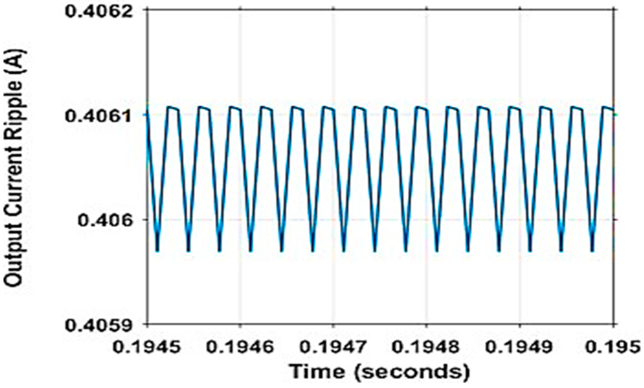
3. Comparison of Performance Parameters
From designing, implementing, and analyzing various topologies such as conventional cuk converter, NICC, NICC with valley-fill. The parameters under consideration include output voltage and current, current and voltage ripple, efficiency, luminous efficacy, flicker index, as well as voltage and current stress across key components. It is observed that in conventional cuk converter the LED voltage obtained is −23.38 V and the LED current obtained is −0.406 A, where the values are negative. To overcome this, NICC is used. In non-inverting cuk converter, the value of LED voltage is 23.39 V, and the LED current is 0.4061, the values are positive. But, in non-inverting cuk converter, the current ripple and voltage ripple are 0.02467% and 0.02993%, respectively. To reduce the ripple, valley-fill circuit is added in the non-inverting cuk converter. The current ripple and voltage ripple have become 0.0174% and 0.0216%, respectively. Hence, the valley-fill circuit introduced to the NICC is introduced to overcome inverting output, current, and voltage ripple, and to increase efficiency.
From Table 3, the conventional cuk converter output voltage obtained, and the output current obtained are negative. In non-inverting cuk converter, the value of LED voltage and current are positive. The value of current ripple and voltage ripple is high in non-inverting cuk converter, and they are rectified in NICC with valley-fill.
Table 3.
Load Side Parameters Comparison.
From Table 4, it can be observed that the efficiency of NICC with valley-fill is high compared to cuk converter and NICC. Similarly, the luminous efficacy, flicker index, and stress are low compared to cuk converter and NICC.
Table 4.
Performance Parameters Comparison.
4. Conclusions
This paper brings forth a comprehensive solution that significantly improves energy efficiency, reduces environmental impact, and propels technological innovation. A novel 10 W and 24 V NICC with valley-fill circuit-based LED driver with the efficiency of 97.13% is proposed. The incorporation of the valley-fill circuit not only enhances energy efficiency but also brings about tangible advantages such as voltage and current stress in semiconductor devices, reduced LED voltage and current ripple. The IEEE Std 1789-2015 determined the flicker regulation of high brightness for mitigating health risks. Therefore, the valley-fill circuit is utilized to reduce the current and voltage ripples by 0.017% and 0.022% to satisfy the IEEE Std 1789-2015. The project’s focus on cost-effectiveness plays a crucial role in making advanced power electronics more accessible, with broad implications across various industries. Furthermore, the mitigation of flicker in the proposed driver by current reducing ripple, the project contributes to a more stable and reliable power supply, significantly impacting sensitive electronic applications.
Author Contributions
Conceptualization, supervision, S.R.; Methodology, Validation, and writing-review and editing, L.P.B.; Investigation, writing–original draft preparation, A.R., D.S. and H.V.B. All authors have read and agreed to the published version of the manuscript.
Funding
This research received no external funding.
Institutional Review Board Statement
Not applicable.
Informed Consent Statement
Not applicable.
Data Availability Statement
Data sharing is not applicable.
Conflicts of Interest
The authors declare no conflicts of interest.
References
- Wang, Y.; Alonso, J.M.; Ruan, X. A Review of LED Drivers and Related Technologies. IEEE Trans. Ind. Electron. 2017, 64, 5754–5765. [Google Scholar] [CrossRef]
- Mrabet, B.M.; Chammam, A.; Nsibi, W. Constant-Current LEDs driver based on DC-DC buck converter with dimming capability. In Proceedings of the 2020 6th IEEE International Energy Conference (ENERGYCon), Gammarth, Tunisia, 28 September–1 October 2020; pp. 204–209. [Google Scholar] [CrossRef]
- Suthar, C.; Kumar, V.I.; Yousefzadeh, V.; Doshi, M.; Maksimović, D. A Composite Converter based Automotive LED Driver. In Proceedings of the 2023 IEEE 24th Workshop on Control and Modeling for Power Electronics (COMPEL), Ann Arbor, MI, USA, 25–28 June 2023; pp. 1–6. [Google Scholar] [CrossRef]
- He, Q.H.; Li, T.; Wang, Q. Dimmable and Cost-Effective DC Driving Technique for Flicker Mitigation in LED Lighting. J. Disp. Technol. 2014, 10, 766–774. [Google Scholar]
- Zhang, H. Reliability and lifetime prediction of LED drivers. In Proceedings of the 14th China International Forum on Solid State Lighting: International Forum on Wide Bandgap Semiconductors (SSL: IFWS), Beijing, China, 1–3 November 2017; pp. 24–27. [Google Scholar]
- Pal, S.; Singh, B.; Shrivastava, A. A Novel Cost-Effective Dual-Colored LED Lighting in Household Applications. IEEE J. Emerg. Sel. Top. Power Electron. 2022, 10, 4425–4434. [Google Scholar] [CrossRef]
- Lu, Z.; Wei-Ming, L. A Single-Stage LED Driver Using Step-Down Cuk/LLC with APWM-PFM Hybird Control. In Proceedings of the 2018 15th China International Forum on Solid State Lighting: International Forum on Wide Bandgap Semiconductors China (SSLChina: IFWS), Shenzhen, China, 23–25 October 2018; pp. 1–4. [Google Scholar]
- Al-Baidhani, H.; Kazimierczuk, M.K.; Reatti, A. Modeling and Control of Bridgeless Single-Switch Non-Inverting AC-DC Cuk Converter in DCM. In Proceedings of the IECON 2022—48th Annual Conference of the IEEE Industrial Electronics Society, Brussels, Belgium, 17–20 October 2022; pp. 1–6. [Google Scholar]
- Shukla, T.; Kalla, U.K. A Single-Stage positive Cuk Converter based Charging System for Light Electric Vehicle Applications. In Proceedings of the 2021 IEEE 2nd International Conference on Smart Technologies for Power, Energy and Control (STPEC), Bilaspur, India, 19–22 December 2021; pp. 1–6. [Google Scholar]
- Oluwafemi, A.W.; Ozsoy, E.; Padmanaban, S.; Bhaskar, M.S.; Ramachandaramurthy, V.K.; Fedak, V. A modified high output-gain cuk converter circuit configuration for renewable applications—A comprehensive investigation. In Proceedings of the 2017 IEEE Conference on Energy Conversion (CENCON), Kuala Lumpur, Malaysia, 30–31 October 2017; pp. 117–122. [Google Scholar]
- Maroti, P.K.; Padmanaban, S.; Wheeler, P.; Blaabjerg, F.; Rivera, M. Modified high voltage conversion inverting cuk DC-DC converter for renewable energy application. In Proceedings of the 2017 IEEE Southern Power Electronics Conference (SPEC), Puerto Varas, Chile, 4–7 December 2017; pp. 1–5. [Google Scholar]
- Babaei, E.; Mahmoodieh, M.E.S. Systematical method of designing the elements of the Cuk converter. Int. J. Electr. Power Energy Syst. 2014, 55, 351–361. [Google Scholar] [CrossRef]
- Lakshmipraba, B.; Seyezhai, R. Reliability Prediction of Bridgeless AC-DC SEPIC with V-Fill for LED Applications. In Proceedings of the 2022 International Conference on Power, Energy, Control and Transmission Systems (ICPECTS), Chennai, India, 8–9 December 2022; pp. 1–6. [Google Scholar]
- Kanamori, M.; Kato, K.; Ishida, K.; Jirachaisophon, P.; Mongkoldee, P.; Shibayama, T. Application of Valley-Fill Circuit to Inverter Air Conditioners. In Proceedings of the 2020 23rd International Conference on Electrical Machines and Systems (ICEMS), Hamamatsu, Japan, 24–27 November 2020. [Google Scholar]
- Wang, L.; Zhang, B.; Qiu, D. A Novel Valley-Fill Single-Stage Boost-Forward Converter With Optimized Performance in Universal-Line Range for Dimmable LED Lighting. IEEE Trans. Ind. Electron. 2016, 64, 2770–2778. [Google Scholar] [CrossRef]
- Lee, J.-Y.; Yoon, Y.-D.; Kang, J.-W. A Single-Phase Battery Charger Design for LEV Based on DC-SRC With Resonant Valley-Fill Circuit. IEEE Trans. Ind. Electron. 2014, 62, 2195–2205. [Google Scholar] [CrossRef]


Disclaimer/Publisher’s Note: The statements, opinions and data contained in all publications are solely those of the individual author(s) and contributor(s) and not of MDPI and/or the editor(s). MDPI and/or the editor(s) disclaim responsibility for any injury to people or property resulting from any ideas, methods, instructions or products referred to in the content. |
© 2025 by the authors. Licensee MDPI, Basel, Switzerland. This article is an open access article distributed under the terms and conditions of the Creative Commons Attribution (CC BY) license (https://creativecommons.org/licenses/by/4.0/).