1. Introduction
The EU regulation on drone operations [
1] defines the “specific” category of operations that should present intermediate levels of risk and require a thorough operational risk assessment to be performed following the Specific Operations Risk Assessment (SORA) methodology [
2]. SORA uses a description of the drone operation and characteristics to assess its main risks, such as the drone colliding with people and infrastructure on the ground of the area of operations (ground risk) or the drone colliding with other aircraft in the area of operations (air risk). The SORA determines a Specific Assurance and Integrity Level (SAIL), which defines the safety objectives that the drone must satisfy.
Within the PHYDIAS project, ONERA developed a new generic approach to assess the safety of Medium-Risk (e.g., either SAIL III or SAIL IV) drone operations, designed by six manufacturers.
The generic approach is based on the incremental development of a four-layer model that supports the safety assessments that are required for Medium-Risk operations:
The safety barrier model describes the operational risk management policy;
The procedure model describes the human and technical tasks that are performed in order to implement the safety barriers;
The functional architecture model describes how on-ground and on-board system functions implement the technical tasks;
The hardware architecture model describes how on-ground and on-board physical resources implement the system functions.
The main achievement of the work presented in this paper is that the proposed generic safety assessment approach was accepted by both the French national Aviation Authority and EASA in the context of SAIL III and IV drone operation authorizations.
In the remainder of this paper, we introduce the safety assessments that are required by the EU regulation for Medium-Risk drone operations. Then we present, for each of the four layers, the method used to describe the layer concepts, failure modes, and failure propagations. We also explain for each of the layers the regulatory and practical results that we achieved. The regulatory result sections explain how the layers can be used to support the required safety assessments. The practical result sections provide some lessons learnt when applying the method with the drone manufacturers to assess their drone designs. The sections provide feedback about the ease of application of the method and explain the main safety flaws that were discovered when we used the proposed approach. Finally, we briefly describe the implementation of the four-layer model using the AltaRica safety modeling language [
3].
2. Safety Assessments Required by EU Drone Regulation
The drone characteristics and operations that were assessed during the PHYDIAS project fit in the SAIL III or SAIL IV levels in the specific category of EU regulation. Various drone configurations (multicopter, helicopter, fixed-wing, lighter-than-air) were assessed. For each drone, we performed a SORA 2.0 assessment that used information about the drone’s characteristics (maximal dimension, mass, range), as well as information about the operations (level of flight, density of overflown areas, etc.). The maximal characteristic dimension of the assessed drones was always below 8 m, with a majority of configurations being around 3 m. The drone mass varied from 2.5 kg to 170 kg, and the range varied between 25 km and 250 km. The two operations considered were electrical, railway, or motorway infrastructure monitoring missions and medical good deliveries. Both operations were Beyond Visual Line of Sight (BVLOS) operations, where the drone remote pilot cannot directly observe the drone trajectory. For these operations, the drones were supposed to fly over either sparsely populated rural areas or populated suburban areas, and they were supposed to fly below 120 m.
Two recent EASA documents detail the safety objectives and Means of Compliance (MoC) for SAIL III [
4] and SAIL IV [
5] levels. The main safety assessments that are required by the regulation for SAIL III and IV for technical issues are as follows:
Functional Hazard Assessment (FHA): This assessment must assess the impact of all possible function degradation scenarios, also taking into account relevant adverse conditions. The FHA helps to define the Failure Conditions and their severity (Catastrophic, Hazardous, Major, Minor, or No Safety Effect).
Probable Failure Assessment (PFA)—Qualitative: This assessment must show that Failure Conditions leading to a Loss of Control of operation (LOC) are not probable. A failure is considered probable when it is expected to occur at least once in the life of the drone.
Probable Failure Assessment—Quantitative: If the qualitative assessment is not conclusive, this assessment must show that the cumulative probability of Failure Conditions leading to an LOC are below an acceptable target. Documents [
4,
5] set the acceptable target to 5.10
−4/Flight Hour for SAIL III and 10
−5/Flight Hour for SAIL IV.
No Single Point of Failure (NSF) Assessment: This assessment must show that Catastrophic Failure Conditions do not result from any single failure.
Development Assurance Level (DAL)
Allocation: This assessment must show that functions, systems, equipment, and items whose development error(s) could directly result in an LOC are developed with an appropriate level of rigor. Documents [
4,
5] set the acceptable level of rigor to DAL D for SAIL III and DAL C for SAIL IV.
3. Safety Barrier Model
3.1. Model Notation
Figure 1 shows a safety barrier model for the management of ground risk. Following the principles of other safety barrier models [
6,
7], this model relates operational barriers such as Land As Soon As Possible (ASAP) or Interrupt Flight, depicted by rectangles in
Figure 1, with situations such as emergency flight, mitigated crash, or unmitigated crash, depicted by rounded boxes. Diamonds represent the question “
Is the Barrier successful?”. The rounded box that is connected to bottom of the diamond is the initial situation. When a barrier is successful, the situation connected to the left of the diamond is the next situation; otherwise, the situation that is connected to top of the diamond is the next situation.
3.2. Failure Modes and Propagations
The model captures the safety policy by describing the effects of barriers when a hazard occurs.
Figure 1 shows the application of the barrier model when assessing the occurrence of a hazard such as the severe degradation of propulsive energy. This hazard occurrence would trigger the initial situation “Unable to perform mission”. The barriers “Abort Mission” and “Divert” are not successful, because we consider that, with a severely degraded propulsion, the drone would not be able to reach the planned destination or to divert to a contingency landing area. Consequently, these two barriers are colored in grey. The next successful barrier could be “Land ASAP”, and the resulting situation would be “Emergency Landing”. In that case, the impact of a severe loss of propulsion would be an “Emergency landing”. If a further failure such as an erroneous control of the trajectory occurs, the “Land ASAP” barrier might not be successful, and the next barrier that should be applied, which is “Interrupt Flight”. In that case, the impact of a partial loss of propulsion combined with an erroneous control of the trajectory would be a crash.
3.3. Supported Assessment
This layer alone does not directly support safety assessments, but it helps define LoC situations and their severity. SAIL III and IV MoC documents provide a list of situations that should be considered LoC. We relate them with three situations in the safety barrier model:
Unmitigated crash represents LoC situations: a crash of the drone with the ground/infrastructure/people, unrecoverable loss of controllability, or controlled flight into the terrain.
Mitigated crash represents LoC situations: an emergency leading to the activation of the flight termination system/parachute/other ground risk mitigation procedures or erroneous activation of the flight termination system/parachute/other ground risk mitigation procedures.
Fly Away represents an LoC situation: the drone leaving the operational volume.
SAIL III and IV MoC documents also provide guidelines on the severity classification of the situations in the model. Situations that directly lead to an LoC, such as a mitigated crash, shall be classified as Hazardous whereas situations that combine a drone failure with the loss of a mitigation, such as an unmitigated crash or Fly Away, shall be classified as Catastrophic. We use colors to represent the situation classifications: green for Minor situations, yellow for Major situations, orange for Hazardous situations and red for Catastrophic situations.
3.4. Practical Results
Drone manufacturers were not using the safety barrier model previously, but they found the notation easy to use, and it helped them clarify the role of barriers. The drone manufacturers worked with very similar barriers and policies, so it was easy to adapt the Ground Risk Barrier model to their drone designs and operations. The adaptation took into consideration some drone characteristics. For instance, we added a barrier called “Hover” for multicopter and helicopter drones, where the drone would perform a stationary flight while waiting for the confirmation of a failure. This barrier can be used to deal with transient external failures such as GNSS or communication loss. The Lighter-Than-Air (LTA) drone also needed some adaptation. We did not change the barriers, but we modified the severity classifications. We considered that, due to the low speed and low crash impact of the LTA, crash situations could be classified as Major instead of Catastrophic, but we did not change the classification of the Fly Away situation.
4. Procedure Model
4.1. Model Notation
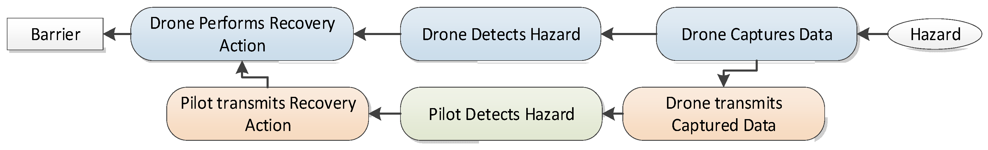
Figure 2 shows a generic procedure model, inspired by the Business Process Modeling notation [
8]. The oval represents the generic hazard that is managed by the procedure. The graph represents the sequences of tasks that implement the procedure. There are tasks that capture data about the hazard, tasks that detect the hazard, tasks that perform a recovery action, and tasks that trigger one of the operational barriers in the safety barrier model. Tasks that are colored in blue are performed by the drone, whereas tasks in green are performed by the remote pilot on the ground. Communication tasks are colored in orange.
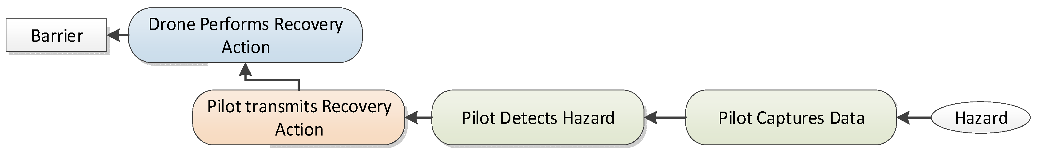
We developed several procedure patterns for various types of allocations of tasks between the remote pilot and the drone. In the dual detection pattern shown in
Figure 2, both the drone and the remote pilot detect the hazard. The drone would use data captured by sensors on board the drone in order to detect the hazard, and the pilot would use the same data after transmission from the drone to the ground. This pattern would be used for drone hazards such as failure of propulsion or trajectory control. In the ground detection pattern shown in
Figure 3, the hazard can only be detected by the pilot. This pattern would be used for a hazard such as weather deterioration, which is communicated directly from a weather information service to the remote pilot.
4.2. Failure Modes and Propagations
Let us suppose that the procedure managing the severe degradation of propulsive energy uses the dual detection pattern presented in
Figure 2. When this hazard occurs, both the drone and pilot tasks are activated, and the nominal result of the procedure should be the activation of the “Land ASAP” barrier. We consider that tasks that are included in the procedure model might fail in two ways: loss or inadvertent activation. The loss of activation of a task interrupts the sequence of tasks linking the hazard with the barrier. For instance, in the previous example, if the task that captures data is not activated, both tasks detecting the hazard cannot be performed, and the barrier would not be activated. If communication tasks are lost, the drone can still detect the hazard and activate the barrier. Consequently, the resulting situation will not be the same for these two cases of failures. The inadvertent activation of a task activates the task when it is not needed. Suppose now that the hazard did not occur and that the task that triggers the barrier is inadvertently activated; then, the barrier “Land ASAP” would be applied, even when it is not needed.
4.3. Supported Assessment
By plugging together the safety barrier and procedure models, it is possible to identify, for any hazard, the tasks and barriers that would be applied, the resulting situation, and its severity. It is also possible to assess the impact of task failures on the management of hazards. References [
9,
10] explain in more detail how the FHA can be consolidated with the models. The failure of tasks that are allocated to the pilot could be caused by either technical issues or human errors. The regulatory safety assessments that we introduced in
Section 2 focus on technical issues. The models could also support other assessments mentioned by the SORA in order to deal with human errors and procedure design flaws.
4.4. Practical Results
Drone manufacturers are required to develop procedures for all important hazards. Furthermore, the procedures are supposed to clearly explain the allocation of tasks between technical systems and the remote pilot. Consequently, it was rather easy to produce a procedure model by selecting the adequate predefined pattern. We found a number of weaknesses in the procedures as defined by the drone manufacturers. Among the common weaknesses are procedures that do not trigger any safety barrier or barriers that are not triggered by any procedure. We also identified procedures that were not robust to the loss of communication between the drone and the remote pilot. Finally, we found inconsistent procedures that could be simultaneously applicable and would trigger different barriers.
5. Functional Model
5.1. Model Notation
Figure 4 shows an extract of the functional architecture model. It contains functions performed by the drone (blue rectangles) and the ground segment (green rectangles), as well as data flows that are exchanged between functions. Functions may be categorized into sub-functions. For instance, the function “Flight Data Acquisition” may be divided into the sub-function “Air Data Acquisition”, which would produce altitude, attitude, speed, and position parameters, and the sub-function “Drone status acquisition”, which would collect information on the health status of the drone’s main capabilities: propulsion, communication, and flight control.
5.2. Failure Modes and Propagations
We consider that a function could either be nominal, lost, or erroneous. The model associates with each function a set of rules that relates the safety quality of the data flows that are produced with its current failure mode and the quality of its incoming data flows. Such a rule could state that when the function is in nominal mode and its incoming data flows are erroneous, it produces erroneous data flows. For a more robust function, the rule could state that the function is able to produce a nominal output, even if some of its incoming data flows are lost or erroneous. These rules are used to assess the propagation of failures through the components of the functional architecture. We can also assess the propagation of failures towards the upper-layer models (procedure and barrier) by connecting task failure modes and function failure modes. For instance, as the function “Flight data acquisition” implements the task “Drone captures data”, a loss of this function will be connected with the loss of activation of the task. We also relate hazards that are found in the procedure model with Failure Conditions that may be defined as functional failures. More details on the connections between the procedure and functional models are given in [
11,
12].
5.3. Supported Assessment
By plugging the functional, procedure and safety barrier models, it is possible to identify combinations of functional failures leading to LoC situations. These combinations can be checked to perform qualitative safety assessments. For instance, for the NSF assessment, it is sufficient to check that no combination of functional failures of size 1 leads to a Catastrophic LoC situation. If we suppose that the loss of a function is probable but that its erroneous behavior is not probable, we can assess PFA—Qualitative by checking that no function loss leads to an LoC situation.
5.4. Practical Results
The description of functions was a weak point of the drone manufacturers’ documentation. It often lacked important information such as an exhaustive description of the data flows connecting functions. The description of aspects helping us to define the failure propagation rules was not always up to date with the actual behavior of the drone. These weaknesses were not difficult to address, but this was a time-consuming task. We identified a few unacceptable single points of functional failure that were corrected by the drone manufacturers.
6. Hardware Model
6.1. Model Notation
The hardware model lists the hardware items that are on-board the drone or on the ground. The model should also include networks that are used for data communication or power distribution. Typical on-board items include sensors, modems, auto-pilot computers, flight control actuators, batteries, engines, and propellers. On-ground items include modems, ground control station computers and displays, and communication equipment with external services. In order to achieve safety, the hardware architecture often includes multiple instances of the same items. For instance, multiple batteries provide power to the items on board the drone. The hardware model also describes the mapping between functions of the functional model and hardware resources that are needed to implement the functions. A function generally requires several hardware resources: sensors to acquire data, computers to treat data, a communication network to transfer data, actuators and electrical power sources, and a network for all these resources.
6.2. Failure Modes and Propagations
We associated to each hardware item either a technology-dependent failure mode (e.g., overheating, short-circuit, leakage, etc.) or a generic failure mode (loss, erroneous) when technology-dependent failure modes were not described in the documentation. We also collected information such as the failure rates and the DAL allocated to the hardware items. Failure propagation rules are simpler than the rules that are used in the functional model. We generally considered that a hardware item failure impacts all the functions that depend on this resource. For instance, if a battery is lost, then all the electrical resources that are used by a function will be lost, and consequently, the function will be lost. If a sensor is erroneous, the function using this resource will provide erroneous results.
6.3. Supported Assessment
If we plug together all the layers, it is possible to perform the qualitative assessments that were performed at the previous stage again, as the functional–hardware mapping might introduce new unacceptable combinations of resource failures. When the failure rates of hardware resources are available, it is also possible to compute the cumulative probability of situations leading to an LoC, as required by PFA—Quantitative. Finally, DAL allocations can also be checked.
6.4. Practical Results
The drone manufacturer documentation provided adequate information regarding the hardware architecture. The failure rates of hardware items were often not available, so we assessed PFA—Qualitative rather than PFA—Quantitative. The mapping of functions on hardware items was often not fully described. We had to interact with the drone manufacturers in order to build a complete mapping. We found new single resource failures leading to Catastrophic LoC situations. This was often related to the mapping of functions on shared resources such as electrical power sources or data communication networks. These flaws were promptly corrected by the drone manufacturers.
7. Implementation with AltaRica
The four layers of models presented in the previous sections are implemented using the AltaRica safety modeling language. In reference [
12], we showed how the layer models can be progressively plugged together: items of the hardware model are connected with functions that are mapped onto them, functions and Failure Conditions in the functional model are connected with tasks and hazards of the procedure model, and tasks trigger barriers in the safety barrier model. Libraries of reusable AltaRica components were developed in order to speed up the development of the models. The Cecilia Workshop [
13] supports the development and assessment of AltaRica models. This tool includes a graphical interactive simulator that plays combinations of failures and shows their impacts on functions, tasks, barriers, and LoC situations. This was useful for validating models with drone manufacturers. The tool also includes a Minimal Cut Set generator that automatically computes the set of minimal combinations of failures leading to LoC situations. Finally, it computes the probabilities of LoC situations. The DALculator tool [
14] helps to explore the DAL allocations. We have developed a new tool that extracts information from the AltaRica model and safety results in order to present them in a Probable Failure Assessment table that was agreed to by the certification authorities.
8. Conclusions
The generic safety assessment was developed by ONERA during the PHYDIAS project. Our work benefited from interactions with both drone manufacturers and the French national Aviation Authority. The results of the safety assessments were included in the documents that are used to grant flight authorizations in France. Then, the approach was successfully applied to one of the fixed-wing drones that we assessed for the first EASA approved SAIL III Design Verification Report [
15].
Our future goal is to share the generic safety assessment that we have presented in this paper widely. We plan to distribute [
16] a number of documents that should help drone manufacturers perform the safety assessments that are required by EU regulations online.
Author Contributions
Conceptualization, methodology, implementation, and writing, P.B., K.D., S.P., T.P. and C.S. All authors have read and agreed to the published version of the manuscript.
Funding
The authors acknowledge the funding of PHYDIAS2 project by DGAC, France Relance 2030, and European Union NextGenerationEU.
Institutional Review Board Statement
Not Applicable.
Informed Consent Statement
Not applicable.
Data Availability Statement
Data are contained within the article.
Conflicts of Interest
The authors declare no conflicts of interest.
References
- European Union Commission. Implementing Regulation (EU) 2019/947 of 24 May 2019 on the Rules and Procedures for the Operation of Unmanned Aircraft; The European Union: Brussels, Belgium, 2019. [Google Scholar]
- JARUS. JARUS Guidelines on Specific Operations Risk Assessment (SORA), Edition Number 2.5. May 2024. Available online: http://jarus-rpas.org/wp-content/uploads/2024/06/SORA-v2.5-Main-Body-Release-JAR_doc_25.pdf (accessed on 1 December 2024).
- Arnold, A.; Griffault, A.; Point, G.; Rauzy, A. The AltaRica formalism for describing concurrent systems. Fundam. Inform. 2000, 40, 109–124. [Google Scholar] [CrossRef]
- EASA. SAIL III Means of Compliance with OSO#05/10/12 “System Safety and Reliability”; EASA: Cologne, Germany, 2023.
- EASA. SAIL IV Means of Compliance with Light-UAS.2510 Equipment, Systems and Installation; EASA: Cologne, Germany, 2024.
- Perrin, E.; Kirwan, B.; Stroup, R. A systematic model of ATM safety: The integrated risk picture. In Proceedings of the Conference on Risk Analysis and Safety Performance in Aviation, Atlantic City, NJ, USA, 19–21 September 2006. [Google Scholar]
- Rabiller, B.; Fota, O.N. Guidance to Applying the Expanded Safety Reference Material (E-SRM); EUROCONTROL Technical Report; EUROCONTROL: Belgium, France, 2023. [Google Scholar]
- Corradini, F.; Ferrari, A.; Fornari, F.; Gnesi, S.; Polini, A.; Re, B.; Spagnolo, G.O. A Guidelines framework for understandable BPMN models. Data Knowl. Eng. 2018, 113, 129–154. [Google Scholar] [CrossRef]
- Bieber, P.; Delmas, K.; Blaye, P.L.; Pizziol, S.; Prosvirnova, T.; Seguin, C. Safety Barrier Diagrams for Specific Operations of Drones. In Proceedings of the 2024 International Conference on Unmanned Aircraft Systems (ICUAS), Chania, Greece, 4–7 June 2024. [Google Scholar]
- Mathou, C.; Delmas, K.; de Saqui-Sannes, P.; Chaudemar, J.C. Safety-oriented dynamic procedure modeling. In Proceedings of the 2024 IEEE International Systems Conference (SysCon), Montreal, QC, Canada, 15–18 April 2024. [Google Scholar]
- Mathou, C.; Delmas, K.; de Saqui-Sannes, P.; Chaudemar, J.C. UAS Procedures Model with System Architecture for Safety Analysis. In Proceedings of the 2024 International Conference on Unmanned Aircraft Systems (ICUAS), Chania, Greece, 4–7 June 2024. [Google Scholar]
- Delmas, K.; Seguin, C.; Bieber, P. Tiered Model-Based Safety Assessment. In Model-Based Safety and Assessment; Papadopoulos, Y., Aslansefat, K., Katsaros, P., Bozzano, M., Eds.; IMBSA 2019, Lecture Notes in Computer Science; Springer: Cham, Switzerland, 2019; Volume 11842. [Google Scholar] [CrossRef]
- Cecilia Workshop Website. Available online: https://satodev.com/cecilia-workhop/ (accessed on 1 December 2024).
- DALculator Website. Available online: https://github.com/onera/dalculator (accessed on 1 December 2024).
- Thales UAS AVEM300 ScaleFlyt Design Verification Report. Available online: https://www.easa.europa.eu/en/domains/drones-air-mobility/drones-evtol-designs/approved-drones-eu-operations/pr-68-thales-uas (accessed on 1 December 2024).
- PHYDIAS Website. Available online: https://w3.onera.fr/PHYDIAS/fr (accessed on 1 December 2024).
| Disclaimer/Publisher’s Note: The statements, opinions and data contained in all publications are solely those of the individual author(s) and contributor(s) and not of MDPI and/or the editor(s). MDPI and/or the editor(s) disclaim responsibility for any injury to people or property resulting from any ideas, methods, instructions or products referred to in the content. |
© 2025 by the authors. Licensee MDPI, Basel, Switzerland. This article is an open access article distributed under the terms and conditions of the Creative Commons Attribution (CC BY) license (https://creativecommons.org/licenses/by/4.0/).

