Proceeding Paper

Study of Proposed SIS Monitoring Strategies for a Lunar Navigation System †

Navigation System Department, DONI, Thales Alenia Space Italia, Via Tiburtina 1232, 00131 Roma, Italy
*
Author to whom correspondence should be addressed.
Presented at the European Navigation Conference 2024, Noordwijk, The Netherlands, 22–24 May 2024.
Eng. Proc. 2025, 88(1), 47; https://doi.org/10.3390/engproc2025088047
Published: 9 May 2025
(This article belongs to the Proceedings of European Navigation Conference 2024)

Abstract

The deployment of a lunar navigation satellite system will be justified by the provision of navigation services to the many planned lunar missions that will include both orbiting and surface users. In this context, system monitoring and system validation will require an innovative approach different from common GNSS terrestrial application, considering the initial absence of a ground station on the lunar surface. A trade-off will be performed between three proposed strategies for the monitoring of navigation signals broadcasted by lunar-orbiting satellites, considering the advantages and disadvantages and proposing the best strategy to verify the structure and/or content of the navigation signal.

1. Introduction

Exploration and exploitation of the Moon and its natural resources are entering a challenging phase. Worldwide national agencies and private companies, boosted by both similar and different motivations, are not only planning but already designing, implementing and launching a large variety of missions: from robotic explorers such as orbiters, landers and rovers to far more complex manned expeditions, it is clear that the current scenario of space engineering, industry and the economy sees the return to the Moon as the next “giant leap” to be taken, paving to way to Solar System exploration and the permanent presence of humankind on other celestial bodies [1]. The high number of missions and this permanent presence, in the long term, justifies the in-parallel deployment of services and infrastructures [2]: among them, a GNSS-like (Global Navigation Satellite System) navigation service is crucial to support not only surface operations but also landing, rendezvous, in-orbit servicing (just like GNSS for Earth users), avoiding and/or enforcing the usage of DTE (Direct-to-Earth) links and on-board sensors (i.e., altimeter, IMU).
The state of the art for this topic includes an initial exploitation of GNSS signals from MEO (i.e., GPS, Galileo) with high-sensitivity space-borne receivers [3], but later this capability will be complemented with the deployment of a dedicated satellite constellation in lunar orbit providing ranging and PVT (Position, Velocity, Timing). Many feasibility studies have been carried out presenting different constellation concepts [4] and some of them are already the object of funding and industrial concern, especially those with satellites in ELFOs (Elliptical Lunar Frozen Orbits) [5]. An ELFO is a peculiar orbital configuration enabled by the combined gravitational pull of the Earth and the Moon, for which the orbital maintenance of a satellite (in terms of the station-keeping propellant budget) deployed on an eccentric and inclined orbit with 90° or 270° argument of periapsis is relatively very low and the trajectory very stable around the nominal orbit [6]. With the lunar South Pole region being the target of many of the aforementioned missions [7], a constellation of four satellites in ELFOs is able to provide a PVT service to users in this region with sufficient continuity and availability (depending on the orbital period and optimized geometry).
In addition to the challenges presented by the design and the deployment of both the system and the service [8], the problem of how to monitor and how to validate the lunar navigation system still stands, since a “lunar ground segment” able to receive, process and analyze the system’s Key Performance Indicators (KPI) will not be foreseen in the early stages of the system, i.e., when one satellite (or, at least, very few) is already orbiting the Moon providing, for example, just a one-way ranging service.
Assuming that this lunar ground segment will also not be present when all the four ELFO satellites have been deployed, the aim of this paper is to present and discuss the feasibility of three alternative monitoring strategies for the navigation signal:
  • Monitoring from Earth: The direct visibility from a ground segment on the Earth will be analyzed and a preliminary link budget is computed in order to derive power levels and discuss the feasibility of this strategy.
  • Cross-monitoring: The analyzed constellation geometry permits extensive visibility time windows between its satellites. Since the FSL (Free Space Loss) of these links could be more representative of a surface user of the navigation service, the link budget is computed but transmission and reception in the same frequency band must be dealt with.
  • Monitoring from lunar orbit: Both the predominant FSL of a Moon-to-Earth link and the issues related to reception of the navigation signal by the lunar satellites could be overcome by lunar-orbiting assets equipping a receiver. Link budget and visibility must be analyzed considering a candidate orbit.

2. Simulation Scenario: Hypothesis and Assumptions

2.1. Space Segment

The assumed space segment for the present work is a constellation of four satellites with Elliptical Lunar Frozen Orbits, orbiting the Moon in a 24 h period trajectory and deployed on three orbital planes equally spaced in RAAN. The argument of periapsis is set to 90 degrees in order for the apolune to be oriented towards the South Polar region and to have the widest visibility windows in that area, while the relative phasing between the satellites is arranged to maximize the contemporary reception of 3 and 4 satellites (Figure 1).
These initial conditions were propagated with STK (Systems Tool Kit) Lunar HPOP (High-Precision Orbit Propagator) from 1 January 2027 to 1 January 2028. The dynamical effects included in the propagation are the lunar gravity model LP150Q (up to 48 for both the order and degree of the gravitational harmonics), the cannonball SRP model with a 0.04 kg/m2 coefficient and third-body perturbations from the Earth and the Sun, whose positions and gravitational parameters come from JPL DE430 ephemeris. The numerical integration is performed by a Runge–Kutta–Fehlberg 7(8) method.
After a first propagation attempt, it was noted that, despite the Keplerian orbital parameters’ behavior in time being enough stable to guarantee their libration around an equilibrium point without significant drift, the relative mean anomaly phasing between the satellites rapidly degraded, severely impacting the geometry of the constellation from the user’s perspective. The initial semimajor axis correction described by Ely [6] has been applied with the aid of STK Astrogator and the embedded Differential Corrector optimizer: a small relative difference between the initial semimajor axes of the four satellites (in order of a few tens of meters or a few kilometers) has been proven capable of constraining the relative mean anomaly in the vicinity of the initial value without any drift and with only short-period oscillations.
The final assumptions on the space segment are related to the navigation payload:
  • The satellite attitude is a standard nadir-pointing towards the center of the Moon, with the navigation antenna deployed in that direction.
  • The navigation antenna is described by its radiation pattern, i.e., the result of the sum between the High-Power Amplifier (HPA) power at the antenna interface (assumed constant) and the antenna gain profile. In our case, both a primary main lobe and secondary side lobes have been considered, in order to obtain a 3D realistic representation (the punctual antenna gain experienced by an endpoint user will be a function of the azimuth and the elevation of such user with respect to the plane of the antenna mount).
  • The maximum off-nadir angle from the antenna boresight that will be set as a threshold for the visibility conditions is 70 degrees.
  • The navigation signal is transmitted in the S-band, with a center frequency of 2.49 GHz [2].

2.2. Ground Segment

The heritage of DTE navigation for lunar and any other interplanetary missions, in terms of ground sites all over the Earth equipped with large antennas and related facilities, will contribute to the first phases of a GNSS-like navigation service for the Moon as a ground segment, not only for the generation of orbit and clock products, for the uplink of navigation data and for TT&C purposes, but also in some way for the reception and the monitoring of the navigation signal-in-space.
In this paper, three ground sites equally spaced in longitude by about 120 degrees (Northern America, Southern Europe, Australia) have been considered in order to always cover the link with the Moon with at least one site.
An elevation mask of 5 degrees’ cut-off angle constrains the visibility, and the antennas are assumed to be Moon-pointing in order to exploit their high directivity and their high gain (i.e., G/T). Standard tropospheric and ionospheric environments, presented in STK, have been injected in the computations of the link losses in the S-band.

3. Analysis and Results

3.1. Monitoring from Earth

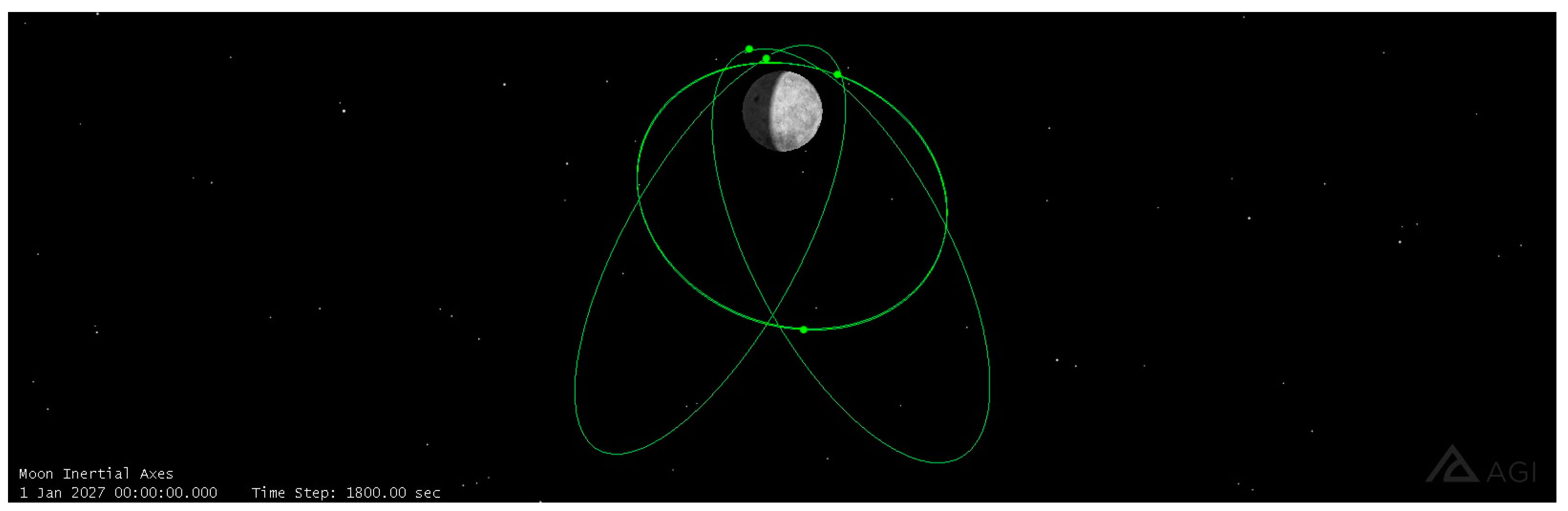
A “chain” object has been created on STK: this embedded function will compute the accesses from a satellite S-band navigation signal to the ground segment, activating the constraint that the access is active when at least one site field-of-view (i.e., S-band receiver on Earth) is in visibility of the signal. This operation has been repeated for the four satellites.
The results for the aforementioned year of simulation has been reported in the following table (Table 1) and in the following figure (Figure 2).
The two percentages in brackets in the second column are the apportionment of the main percentage (i.e., per satellite, year fraction of cumulative visibility of its S-band signal from at least one ground site) between visibility from exactly one site and visibility from exactly two sites at the same time, also reflected in “(1 site)” duration in the fourth column as the maximum duration of an interval for which the signal is visible from just one site.
From a daily point of view, which can be considered as more fitting for operation scheduling and the repeatability of the monitored products, the reception of each of the four signals is guaranteed every day from a minimum of half an hour to a maximum of almost the entire day, with overall (i.e., in an absolute sense, not daily) continuous visibility of an S-band signal for a maximum of 20/21 h. It has to be specified that this is an aggregated time, divided into a number of individual daily windows from one to four. Moreover, the disposition of these windows during each day drift along the year, with overall data gaps of almost 24 h.
For redundancy and RAMS purposes, the analysis results related to visibility from just one site are interesting: this condition occurs for half of the visibility epochs, with windows that can last up to almost 8 h. The high reliability of the ground facilities and/or a sufficient number of antennas per site must be guaranteed.
Visibility of the signal as a standalone is not sufficient for a proper monitoring: the RF power level at the ground site antenna must be high enough to decode the embedded data. For each satellite-to-site link (a total of 12 links), the RF-received power level (from now on, PoG for ground assets and PoS for space assets) has been computed with the following mathematical relation (1):
PoG/PoS [dBW] = EIRP(Az, El) [dBW] + PL(slant range, ground site/space asset coordinates) [dB]
with the EIRP extrapolated from the radiation pattern as a function of the azimuth (Az) and elevation (El) of the ground site/space asset as seen from the satellite antenna and path losses (PL) as a sum of the Free Space Loss (function of satellite-to-site/satellite slant range and frequency) and atmospheric losses, computed by STK with embedded models. Two thresholds of −199 dBW and −189 dBW have been set for availability computation [9], whose results have been collected in the following table (Table 2).
The cases with the −189 dBW threshold are not applicable because the maximum absolute values (i.e., the best case for each of the satellite) are between −190.4 dBW and −190.9 dBW.
Assuming that the correct reception and interpretation of the signal occurs when the −199 dBW power level is reached or overcome, the combination of Table 3’s availability information and Table 2’s visibility information translates into guaranteed daily monitoring of at least one hour per day but interrupted, within the single windows, by gaps because of the low received RF power level. The entity and the related impact of these power drops on the quality of the monitoring must be investigated.
It is here remarked that thresholds have been proposed in the mentioned references for the links from MEO to the Moon and for space-borne receivers to be equipped on board lunar missions. In this paper, they have been considered applicable for the opposite direction: despite the additional atmospheric contribution that arises from the receivers being on the Earth surface and the possible interferences given by other systems, the typical high antenna G/T of ground sites used for space communications has been considered as a highly compensative effect.
An analysis on the site workload in terms of signal reception has been carried out and summarized in the following table (Table 3).
For the main part of the time for which an antenna is receiving S-band signals, it is just one satellite, and almost never three or four of them at the same time. On the other hand, for more than half of the time over one year, each site is not active at all.

3.2. Cross-Monitoring

The limitations of the monitoring from Earth are high Free Space Losses due to slant ranges of up to 400 thousands km, atmospheric losses and stringent visibility constraints due to the relative motion between the Earth and the Moon, combined with the Earth’s rotation and ELFO satellites’ orbital motion. In the following section, the possibility for the ELFO satellites themselves to directly receive S-band signals from other elements of the constellation is considered and its effects analyzed.

3.2.1. Case 1: Always Rx + Tx

The first case considers the simultaneous transmission and reception capability for each satellite. This means that, from a scenario point of view, both sides are not constrained in time and access is granted every time the receiving asset is in view of the transmitting asset field-of-view. An omnidirectional receiver is assumed (i.e., no constraint on the direction of the signal).
In the following table (Table 4), the visibility of each satellite S-band signal from at least one of the other satellites is reported.
As expected from the constellation geometry, every performance indicator has highly improved: total time of visibility, redundancy, daily availability, continuity, gaps.
From the point of view of the receivers’ workload, there is always at least one S-band signal in view (except the ELFO 4 receiver, for which it is 99.37% over one year) and there are even windows for which all of them (3) are visible. The availability of reception of three S-band signals and Position Dilution Of Precision (PDOP) availability of the receiver have been computed and reported in the following table (Table 5).
The possibility of in-orbit or post-processing PVT (on the assumption that just three satellites are needed because the “user” performing the PVT is a satellite of the same constellation and the same clock is assumed) must be investigated, with some windows’ length being favorable for the convergence of a standard algorithm. Anyway, the geometry issues (PDOP availability around 80% when considering 10 as a threshold value) and signal-in-space error (SISE) of the constellation satellites [10] must be tackled.
The RF power levels reached at the receiving satellites and the availability with respect to the thresholds have been computed using (1) (Table 6).
Table 7 shows another main advantage of this technique: the much higher RF power level due to the reduced link losses (one order of magnitude lower slant ranges and no atmospheric losses). In addition, the receiving assets are aligned towards transmitting assets boresight for most of the time, resulting in higher EIRP in the link budgets.

3.2.2. Case 2: Rx or Tx

Despite the clear advantages of the “always Rx + Tx” scenario, there is also a clear disadvantage of reception and transmission in the same frequency, which introduces several interferences at both sides. In order to manage this limitation, it has been decided to analyze the same performance indicators presented in the previous section but assuming complementary usage of an S-band HPA and S-band receiver along the orbit: the first will be switched on where the ground track is below 6° N latitude and switched off elsewhere, the second will have the opposite functioning.
This latitude threshold has been derived by analyzing the first ground track latitude for which the satellite is in visibility for a user in a service volume defined in the South Pole region (from 70° S latitude to 90° S latitude), along one year, and taking the maximum value experienced in this year: this means that the S-band payload is “useful” just for the portions of the lunar surface below this value.
Analysis results are resumed in the following tables (Table 7, Table 8, Table 9).
As expected from the limited availability of the satellite functions and for the orbit geometry (the reception phase corresponds to the trajectory portion near the perilune, so it is relatively brief with respect to the transmission phase), all of the time visibility percentages are severely reduced while the PoS levels are not affected, but the PDOP availability has increased (with more favorable geometries despite the highly reduced visibility windows) and the daily availability is interestingly stable for around a couple of hours per day (suggesting that the overall visibility reduction is mainly due to the shrinking of the longest windows along the year).

3.2.3. Case 3: Rx or Tx + Earth

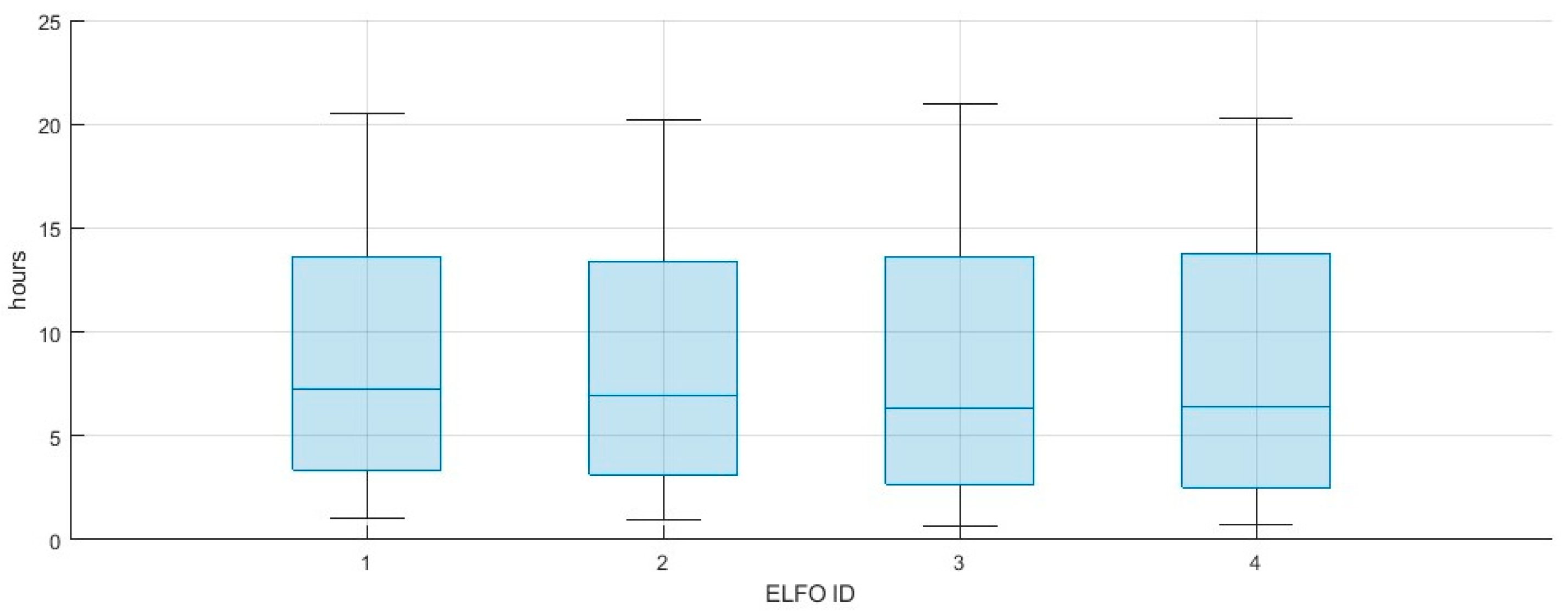
In this last case, a combination of monitoring from Earth using ground sites and from lunar orbit using ELFO satellites receivers when not in visibility from the South Pole is analyzed: hereafter, the S-band signal is considered as monitored when at least one among these four assets is in visibility. The results are summarized in the following table (Table 10) and in the following figure (Figure 3).
As a reference, monitoring from Earth is compared: despite the ELFO satellites, the HPA is switched off for entire portions of the orbit, and the additional receiving asset with respect to the Earth sites resulted in incremented visibility, with higher daily availability (divided into more individual windows), lower gaps and lower slots with just one asset receiving.

3.2.4. Omnidirectional Antenna on-Board vs. Pointed Antenna

The strong assumption of an omnidirectional antenna for the on-board receivers is justified by the ongoing studies on the complex attitude required by the satellite of such a constellation: at least, the nadir-pointing for the S-band transmitter antenna, Earth-pointing for the TT&C antenna and Sun-pointing for the solar panels are all to be satisfied with some level of accuracy. For this reason, it is difficult at this level of maturity to also introduce such a constraint on the S-band receiver antenna.
Anyway, a preliminary analysis has been run, starting from “Case 1: always Rx + Tx”, introducing a standard nadir-pointing with Sun constraint for the ELFO satellites (i.e., body Z-axis aligned with nadir and body Y-axis projection on XZ-plane aligned with Sun direction, for the solar panels) and constraining S-band reception from just one plane of the XYZ body reference (i.e., FoV = 180° and a total of five possible direction, excluding the nadir).
The best numbers for the availabilities correspond to a receiver antenna pointing at the Az-El coordinates (90°, 0°) in a satellite body frame, with values still between 8% and 11% over one year (they were around 100% without this constraint). Given the uncertainty in the final attitude of the satellite, there is some margin for optimization, but the usage of an omnidirectional receiver antenna is strongly suggested in case this strategy is picked.

3.3. Monitoring from Lunar Orbit

The issues caused by the simultaneous roles of transmitters and receivers exercised by the ELFO satellites are overcome by decoupling these functions in the monitoring system and considering an independent orbiter able to receive the S-band signals, in this way also keeping the advantages of the reduced losses and improved geometry.
The effect of orbital drift due to Earth perturbations is mitigated choosing a low orbital period (i.e., two hours, or 123 km altitude), while the inclination is set to 90 degrees (polar orbit, in order to be aligned with South-Pole coverage of the ELFO constellation) and the eccentricity to zero (circular orbit). The orbiter has been equipped with a receiver and the reception has been assumed to be possible just from the zenith-pointing plane of the satellite. This last assumption has been made with a realistic placement of the receiver in mind on the panel pointing outward, i.e., towards space and towards the ELFO satellites.
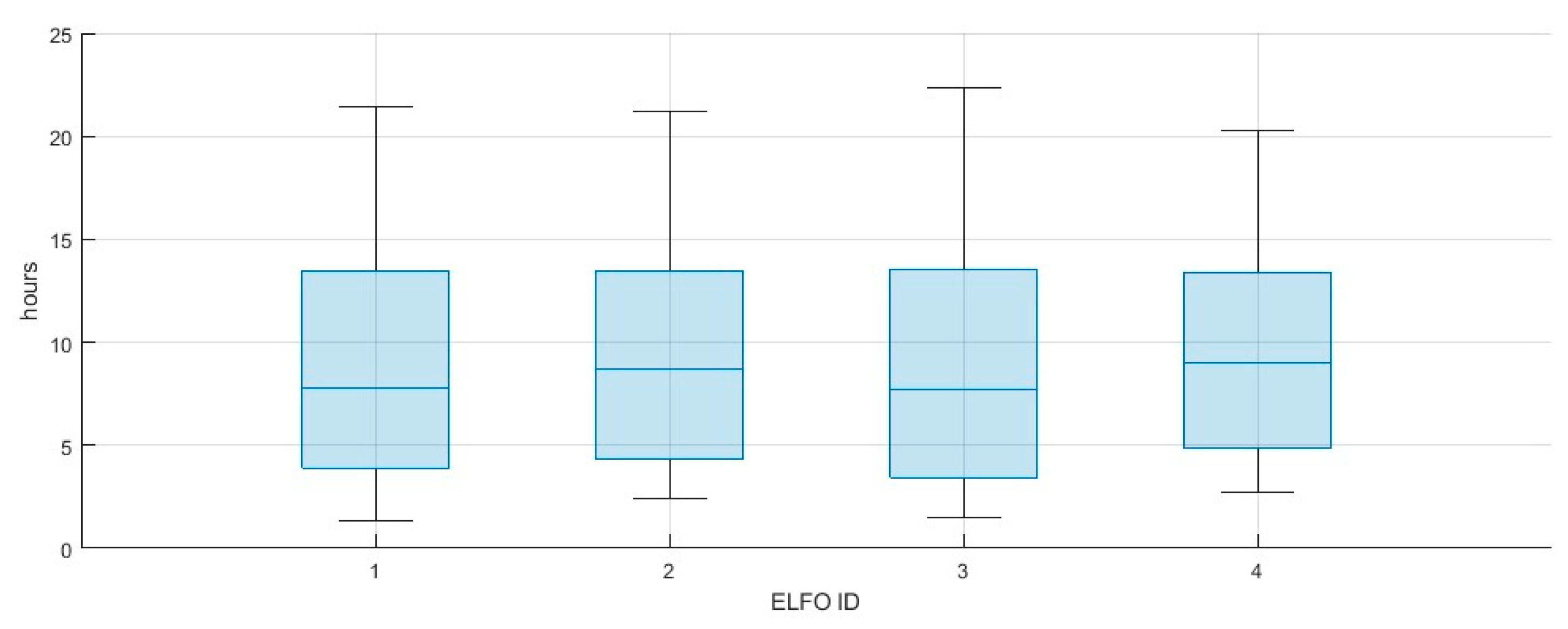
In the first table (Table 11), the availability and reception of multiple signals is analyzed, also presenting geometrical conditions for a possible PVT by the orbiter itself.
In the second table (Table 12), the RF power level of the different S-band signals from the orbiter side are obtained and availabilities are computed.
The “total time in view” KPI exhibits higher values with respect to the cases in which monitoring from Earth has been considered, with a stable daily availability between 8 and 11 h and highly acceptable power levels. The other way around, the possibility to compute the PVT is constrained both in time and in geometry by the high velocity of the orbiter on its orbit, that leads to highly non-continuous and un-symmetric exploitation of the slots where the four ELFO satellites are above the South Pole. Moreover, not only must the SISE analysis of the S-band signals be faced, but also an accurate orbit determination of the orbiter is needed as a pre-condition for the PVT. These two last further analyses, together with an eventual optimization of the orbital parameters of the orbiters in order to improve the relative geometries with the ELFO constellation, are a clear way forward for this Case 3.

4. Conclusions and Future Work

In this paper, the visibility, availability, possibility of PVT and RF power levels have been investigated in the field of lunar navigation system S-band signal exploitation for monitoring and validation purposes, and the results presented. The overall scenario has been set with the assumptions of a four-satellite constellation in an ELFO and three ground sites equipped with high-G/T antennas (able to cope with low received power on the ground, up to −190 dBW). In the hypothesis of no lunar ground segment being able to perform these operations in a standard way, like for the Earth GNSS, three possibilities are proposed and explained with preliminary results: Monitoring from Earth permits good enough daily availabilities and time slots, but the signal losses are significant and online PVT is not feasible. Cross-monitoring is practically possible only when alternating transmitter and receiver functions, constraining daily availability to a few hours and the PVT possibility to minutes, but the DOP and power level results are very favorable (and, when used in combination with Earth monitoring, there are slight improvements in the monitoring KPI). Monitoring by the orbiter would need its accurate OD, and the geometries for PVT are not very good, but its daily availability and power levels are a strong advantage. From this recap, it is evident that a combination of these solutions should be implemented because each of them carries important pros and equally important cons. In order to deepen this work and to obtain further elements for a choice, a characterization of the navigation message is needed and analysis of the actual decoding performances should be computed, together with a PVT analysis comprehensive of positioning performance analysis.

Author Contributions

All authors contributed equally to this work. All authors have read and agreed to the published version of the manuscript.

Funding

This research received no external funding.

Institutional Review Board Statement

Not applicable.

Informed Consent Statement

Not applicable.

Data Availability Statement

Data are contained within the article.

Conflicts of Interest

All authors are employed by the company Thales Alenia Space Italia and declare that the research was conducted in the absence of any commercial or financial relationships that could be construed as a potential conflict of interest. The company had no role in the design of the study; in the collection, analyses, or interpretation of data; in the writing of the manuscript, or in the decision to publish the results.

References

  1. ISECG Global Exploration Roadmap Supplement Update 2022. Available online: https://www.globalspaceexploration.org/wp-content/isecg/GER_Supplement_Update_2022.pdf (accessed on 7 October 2022).
  2. LunaNet Interoperability Specification Document. Available online: https://www3.nasa.gov/sites/default/files/atoms/files/lunanet_interoperability_specification_version_4.pdf (accessed on 12 September 2022).
  3. Delépaut, A.; Giordano, P.; Ventura-Traveset, J.; Blonski, D.; Schönfeldt, M.; Schoonejans, P.; Aziz, S.; Walker, R. Use of GNSS for lunar missions and plans for lunar in-orbit development. Adv. Space Res. 2020, 66, 2739–2756. [Google Scholar] [CrossRef]
  4. Musacchio, D.; Iess, L.; Carosi, M.; Capolicchio, J.; Eleuteri, M.; Stallo, C.; Di Lauro, C. Design of Earth Moon Halo Orbits for a Global Lunar PNT Service. In Proceedings of the ION GNSS+ 2021, St. Louis, MI, USA, 20–24 September 2021. [Google Scholar]
  5. Iannone, C.; Carosi, M.; Eleuteri, M.; Stallo, C.; Di Lauro, C.; Musacchio, D. Four Satellites to Navigate the Moon’s South Pole: An Orbital Study. In Proceedings of the ION GNSS+ 2021, St. Louis, MI, USA, 20–24 September 2021. [Google Scholar]
  6. Ely, T.A. Stable Constellations of Frozen Elliptical Inclined Lunar Orbits. J. Astronaut. Sci. 2005, 53, 301–316. [Google Scholar] [CrossRef]
  7. Li, S.; Lucey, P.; Milliken, R.E.; Hayne, P.O.; Fisher, E.; Williams, J.P.; Hurley, D.M.; Elphic, R.C. Direct evidence of surface exposed water ice in the lunar polar regions. Proc. Natl. Acad. Sci. USA 2018, 115, 8097–8912. [Google Scholar] [CrossRef] [PubMed]
  8. Stallo, C.; Di Lauro, C.; Carosi, M.; Zini, E.E.; Cretoni, D.; Musacchio, D.; Perugia, S.; Boomkamp, H.; Giordano, P.; Albanese, C.; et al. Candidate System concepts for a Lunar Satellite Navigation System. In Proceedings of the NAVITEC 2022, Noordwijk, The Netherlands, 5–7 April 2022. [Google Scholar]
  9. Capuano, V. GNSS-Based Navigation for Lunar Missions. Ph.D. Thesis, École Polytechnique Fédérale de Lausanne, Lausanne, Switzerland, 2016. [Google Scholar]
  10. Stallo, C.; Di Lauro, C.; Carosi, M.; De Leo, L.; Cappa, M.; Musacchio, D.; Cretoni, D.; Boomkamp, H.; Giordano, P.; Swinden, R.; et al. Lunar Navigation System ODTS Signal in Space Error Analysis. In Proceedings of the 2023 European Navigation Conference (ENC), Noordwijk, The Netherlands, 31 May–2 June 2020. [Google Scholar]
Figure 1. Visualization of the chosen constellation at simulation start time on STK “3D Graphics Window”, with the three in-phase satellites at perilune and the other one at apolune.
Engproc 88 00047 g001
Figure 2. Box plot of daily availability from Earth for each ELFO satellite.
Engproc 88 00047 g002
Figure 3. Box plot of daily availability from Earth + ELFO for each ELFO satellite.
Engproc 88 00047 g003
Table 1. Visibility of satellite S-band signal from at least one ground site (percentages over one year).
SatelliteTotal Time in View (%)Daily AvailabilityMax WindowMax Gap
ELFO 135.45% (20.00 + 15.45%)1.06 h–20.5 h20.56 h (6.85 h 1 site)23.22 h
ELFO 234.96% (18.92 + 16.04%)0.98 h–20.2 h20.33 h (7.34 h 1 site)23.23 h
ELFO 334.15% (17.87 + 16.28%)0.63 h–21 h21.20 h (7.21 h 1 site)23.46 h
ELFO 434.00% (18.89 + 15.11%)0.72 h–20.3 h21.24 h (7.39 h 1 site)23.47 h
Table 2. Availability of RF power level on ground for each satellite-to-site link (percentages with respect to visibility epochs).
SatelliteSouthern EuropeAustraliaNorthern America
ELFO 132.36% (−199 dBW)36.73% (−199 dBW)38.38% (−199 dBW)
ELFO 237.79% (−199 dBW)38.51% (−199 dBW)34.31% (−199 dBW)
ELFO 338.66% (−199 dBW)35.17% (−199 dBW)37.80% (−199 dBW)
ELFO 435.12% (−199 dBW)37.58% (−199 dBW)35.82% (−199 dBW)
Table 3. Visibility conditions (geometric only) from each ground site (percentages over one year).
Site1 SIS in View2 SIS in View3 SIS in View4 SIS In ViewTotal
Southern Europe29.56%14.36%1.41%~0%45.32%
Australia27.61%17.98%2.49%~0%48.08%
Northern America27.46%16.17%2.69%~0%46.33%
Table 4. Visibility of satellite S-band signal from at least one other satellite (percentages over one year). Percentages in brackets in the first column are the availabilities of signal reception from one, two and three receivers.
SatelliteTotal Time in View (%)Daily Avail.Max WindowMax Gap
ELFO 1~100% (0.99 + 35.91 + 63.09%)23.93 h–24 h265 d (0.74 h 1 sat)4.27 min
ELFO 2~100% (1.59 + 29.26 + 69.14%)23.93 h–24 h331 d (0.90 h 1 sat)3.34 min
ELFO 3~100% (2.61 + 42.15 + 55.24%)23.95 h–24 h323 d (1.06 h 1 sat)3.04 min
ELFO 499.13% (37.63 + 16.72 + 44.78%)21.8 h–24 h37 d (5.39 h 1 sat)2.20 h
Table 5. Availability and PDOP availability of receiving three S-band signals, for each satellite (percentages over one year).
SatelliteAvailability of Three Signals in ViewPDOP < 5PDOP < 7.5PDOP < 10
ELFO 169.62% (Max: 12.76 h)72.94%82.79%87.28%
ELFO 269.26% (Max: 18.10 h)66.30%78.23%83.71%
ELFO 351.99% (Max: 6.69 h)62.25%73.98%79.88%
ELFO 444.48% (Max: 5.82 h)91.39%95.84%97.53%
Table 6. Availability of RF power level for each satellite-to-satellite link (percentages with respect to visibility epochs: first percentage is >−199 dBW, second percentage is >−189 dBW).
From/toELFO 1ELFO 2ELFO 3ELFO 4
ELFO 1/97.93%, 93.73%97.66%, 92.96%97.47%, 93.39%
ELFO 298.06%, 94.00%/96.09%, 89.37%95.30%, 87.33%
ELFO 397.48%, 92.62%96.76%, 90.45%/92.44%, 86.53%
ELFO 496.91%, 92.64%95.37%, 87.29%92.42%, 86.48%/
Table 7. Visibility of satellite S-band signal from at least one other satellite (percentages over one year)—HPA switching-off when nadir latitude above 6° N. Percentages in brackets in the first column are the availabilities of signal reception from one, two and three receivers.
SatelliteTotal Time in View (%)Daily Avail.Max WindowMax Gap
ELFO 18.73% (7.44 + 1.29 + 0%)0.90 h–3.30 h2.34 h (2.34 h 1 sat)22.42 h
ELFO 211.96% (11.74 + 0.22 + 0%)2.17 h–3.75 h2.35 h (2.35 h 1 sat)11.98 h
ELFO 38.66% (8.44 + 0.22 + 0%)1.43 h–2.77 h1.65 h (1.64 h 1 sat)11.90 h
ELFO 413.25% (5.41 + 4.88 + 2.96%)2.67 h–3.72 h3.71 h (1.58 h 1 sat)21.30 h
Table 8. Availability and PDOP availability of receiving three S-band signals, for each satellite (percentages over one year)—HPA switching-off when nadir latitude above 6° N.
SatelliteAvailability of Three Signals in ViewPDOP < 5PDOP < 7.5PDOP < 10
ELFO 12.91% (Max: 1.58 h)31.31%91.74%99.95%
ELFO 20.17% (Max: 0.32 h)92.49%100%100%
ELFO 3~0% (Max: 2.62 min)10.00%100%100%
ELFO 43.98% (Max: 0.91 h)100%100%100%
Table 9. Availability of RF power level for each satellite-to-satellite link (percentages with respect to visibility epochs)—HPA switching-off when nadir latitude above 6° N.
From/toELFO 1ELFO 2ELFO 3ELFO 4
ELFO 1/92.78%, 82.88%97.86%, 94.36%100%, 100%
ELFO 295.44%, 86.86%/96.97%, 92.01%100%, 100%
ELFO 398.02%, 94.37%97.68%, 92.90%/100%, 100%
ELFO 499.85%, 99.57%100%, 100%100%, 100%/
Table 10. Visibility of satellite S-band signal from at least one monitoring asset (percentages over one year). Percentages in brackets in the first column are availabilities of signal reception from one, two, three and four receivers.
SatelliteTotal Time in View (%)Daily AvailabilityMax WindowMax Gap
ELFO 137.52% (20.84 + 15.40 + 1.09 + 0.18%)1.35 h–21.45 h21.73 h (6.85 h 1 mon)13.81 h
ELFO 239.98% (23.20 + 14.79 + 1.96 + 0.03%)2.45 h–21.18 h21.39 h (7.04 h 1 mon)11.93 h
ELFO 337.71% (21.18 + 15.13 + 1.36 + 0.03%)1.50 h–22.38 h22.15 h (6.80 h 1 mon)11.54 h
ELFO 440.64% (18.78 + 16.72 + 3.59 + 1.13%)2.72 h–20.25 h21.24 h (6.65 h 1 mon)21.29 h
Table 11. Visibility of satellite S-band signals from the receiving orbiter (percentages over one year).
# Signals In ViewTotal Time (%)PDOP Availability (%)
028.65%/
122.86%/
217.92%/
316.11%/
414.45%26.81% (<5), 46.27% (<7.5), 59.03% (<10)
>= 171.35%/
>= 330.57%49.41% (<5), 64.13% (<7.5), 72.63% (<10)
Table 12. Visibility, daily availability and RF power levels for each satellite S-band signal from the receiving orbiter (percentages over one year).
SatelliteTotal Time in View (%)Daily AvailabilityPoS Availability (%)
ELFO 140.55%8.35–10.63 h99.89%, 99.70%
ELFO 241.85%8.70–10.66 h99.92%, 99.77%
ELFO 341.21%8.82–10.93 h99.92%, 99.80%
ELFO 441.24%8.93–10.83 h99.94%, 99.82%
Disclaimer/Publisher’s Note: The statements, opinions and data contained in all publications are solely those of the individual author(s) and contributor(s) and not of MDPI and/or the editor(s). MDPI and/or the editor(s) disclaim responsibility for any injury to people or property resulting from any ideas, methods, instructions or products referred to in the content.

