Abstract
In this paper, we introduce a robust beamforming technique using array antennas. The proposed solution constitutes two stages; the first stage exploits the space-alternating generalized expectation-maximization (SAGE) algorithm to decompose the received GNSS signal into its constituent signals, i.e., direct and reflected signals. The SAGE algorithm estimates the angle of arrival (AoA) and the received covariance matrix for both the direct and reflected signals. The second stage, on the other hand, utilizes the Minimum Variance Distortionless Response (MVDR) algorithm to produce the weight vector that steers the main beam towards the satellite’s direction and the nulls towards the multipath effect. The MVDR uses the AoA of the direct path and the covariance matrix of the reflected path to minimize the multipath effect. The experimental results reveal that the proposed technique improves the received signal strength and the location estimation accuracy, as compared to a single-antenna system. Furthermore, the proposed technique outperforms the traditional MVDR technique in the tested environment. Finally, the 95% 3D position error of the proposed solution is 5.2 m, and the position dilution of precision (pdop) is 0.84.
1. Introduction
Navigation services currently deploy the state-of-the-art Global Navigation Satellite System (GNSS) for outdoor positioning. However, due to the long communication link, the Carrier-to-Noise ratio (CN0) values of the GNSS signals received on the ground are low. Accordingly, the GNSS services are very limited in urban and canyon-like environments. In such environments, the received signals will be either obstructed by a physical barrier or distorted by the multipath effect. To overcome this limitation, several techniques have been proposed in the literature. Some techniques rely on the super correlator approach [1]. This approach depends heavily on the mobility of the GNSS receiver; therefore, it is not suited for static scenarios. Other techniques that rely on a dual polarization antenna (DPA) have also been proposed in the literature [2]. Those techniques are very appealing due to the exploitation of a compact antenna that consists of a right-hand circular polarization (RHCP) antenna and a left-hand circular polarization (LHCP) antenna. Nonetheless, the performance of those techniques is limited and dependent on the correct characterization of the DPA; therefore, those techniques are not entirely suitable for low-cost COTS hardware. The final and most effective approach, which can mitigate the multipath effect and increase the received CN0 level, involves spatial diversity techniques by means of array antenna systems [3].
Array antenna systems have been exploited in various applications, e.g., multipath and interference mitigation; angle of arrival (AoA) estimation; and localization [4,5,6,7,8,9,10,11,12,13]. Consequently, over the past years, array antennas have been deployed in GNSS receivers either to provide a spatial filter or to improve the CN0 level by using beamforming techniques. Fernández-Prades et al. [5] provided an overview of the GNSS receivers that utilize array antennas to mitigate interference signals (and the multipath effect) and to improve the received signal strength. Nonetheless, the current multipath mitigation techniques depend mostly on either the subspace decomposition (i.e., eigen-based beamforming); or Minimum Variance Distortionless Response (MVDR). The performance of those algorithms deteriorates significantly in the presence of correlated signals, which is the case for the multipath effect [11].
In this paper, we address the aforementioned shortcoming by providing a robust beamforming technique using array antennas. The proposed solution constitutes two stages; the first stage exploits an array antenna system to decompose the received signals into direct and reflected signals. The proposed solution deploys the space-alternating generalized expectation-maximization (SAGE) algorithm with the acquired complex samples (from every antenna during the acquisition stage). The second stage, on the other hand, exploits the MVDR algorithm to produce the weight vector that steers the main beam towards the satellite’s direction and the nulls towards the multipath effect. The main difference between the proposed two-stage beamforming technique and a traditional MVDR beamformer is that we deploy the MVDR technique using the de-correlated signals’ covariance matrix. Those signals are decomposed using the SAGE algorithm in the first stage. On the other hand, the traditional MVDR technique directly exploits covariance matrix of the received signals.
In the following sections, the proposed technique will be introduced; followed by the experimental results and discussion; and finally, the conclusions of this paper will be drawn.
2. The Proposed Technique
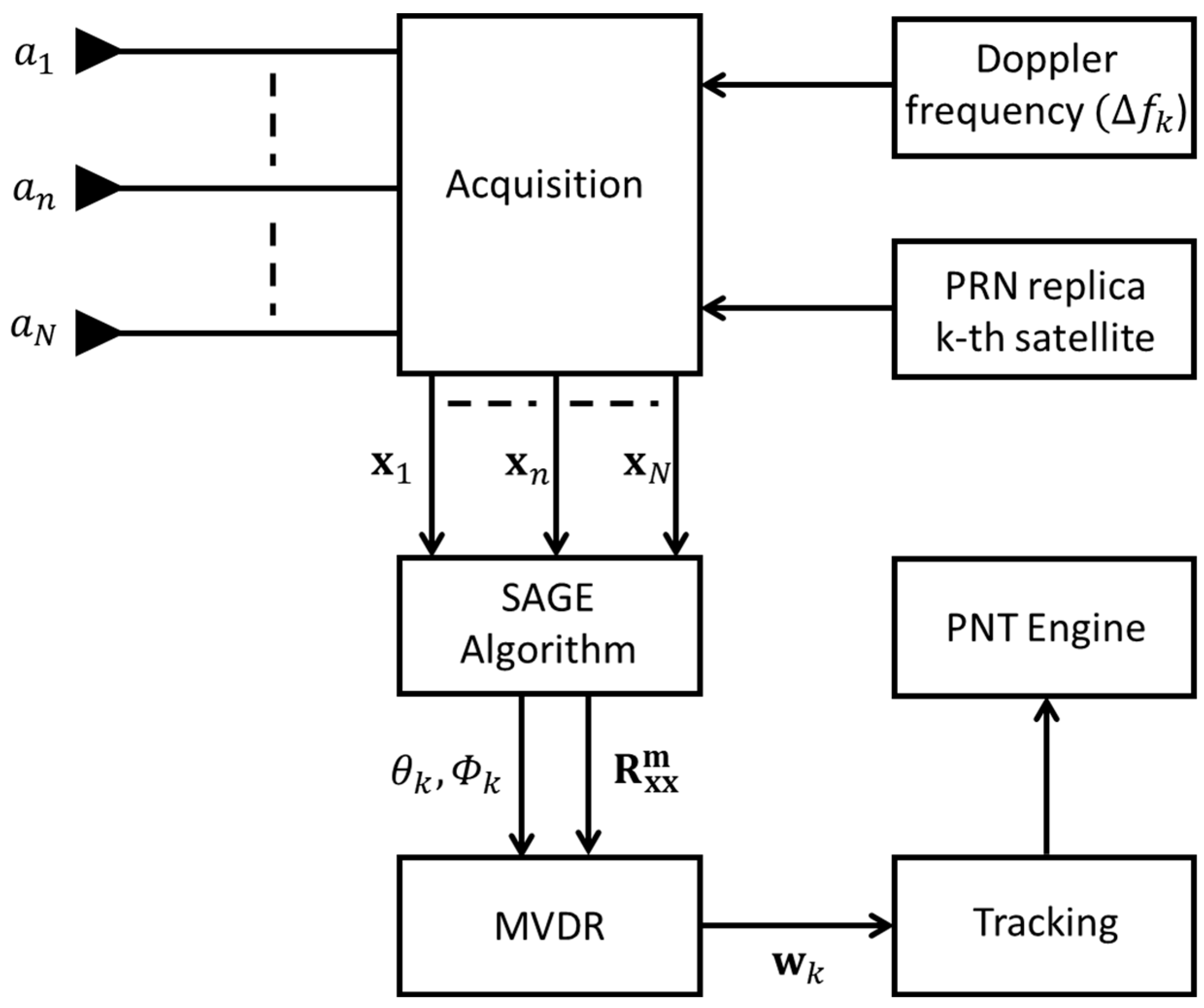
In this section, we present the beamforming strategy adopted during the acquisition process. Figure 1 shows a schematic of the proposed technique. As can be seen, the proposed technique utilizes a two-stage procedure as follows:
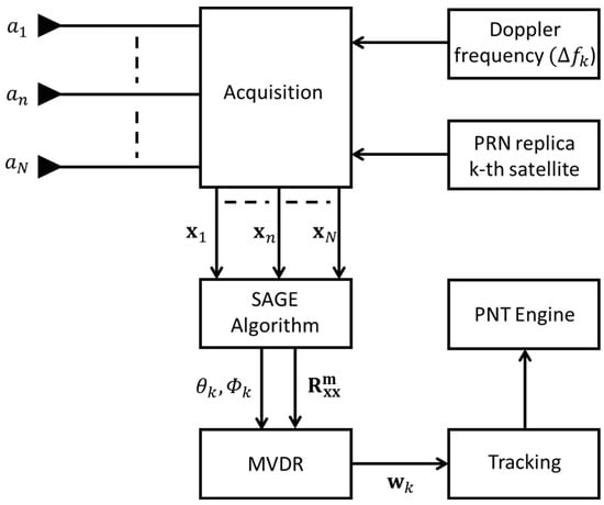
Figure 1.
A schematic representation of the proposed technique. The RF chains of the N antenna elements will be digitized and subjected to the acquisition process. During the acquisition, the complex symbols (from all the N antennas) that are associated with the codephase and the doppler frequency shift () will pass to the SAGE algorithm. The SAGE algorithm estimates the direct and reflected signals’ parameters. The elevation () and the azimuth () of the direct path, which is aimed in the direction of the k-th satellite, and the reflected signal covariance matrix will be passed to the MVDR beamformer. The MVDR algorithm will estimate the weight vector () and pass it to the tracking process. Afterwards, a typical GNSS processing is conducted to provide the PNT solution.
The first stage exploits the acquired complex symbols (i.e., the complex IQ symbols that are associated with the k-th satellite codephase and doppler frequency for every antenna element). During this stage, the SAGE algorithm is used to estimate the AoA and the covariance matrices of the direct and reflected GNSS signals; for details regarding the array signal processing with the GNSS signals, the reader is referred to [3]. The SAGE algorithm employs a maximum likelihood estimator to jointly estimate the parameters of the signals received [14]. It can estimate the AoA and the covariance matrices of highly correlated signals based on a few received signal samples. This capability allows the SAGE algorithm to decompose the received signal into its constituents (i.e., direct and reflected signals). This capability is extremely important in urban environments, due to the presence of the intensive multipath effect [11].
The second stage, on the other hand, exploits the MVDR algorithm to produce the weight vector that steers the main beam towards the satellite’s direction and the nulls towards the multipath effect [13]. The MVDR algorithm utilizes the AoA of the direct signal and the covariance matrix that is associated with the reflected signals to estimate the k-th weight vector that is associated with the k-th satellite. By exploiting , which is provided by the SAGE algorithm, the MVDR beamformer will place nulls only in front of the reflected signals. Furthermore, the covariance matrix of the reflected signals is now independent of the direct signal. Hence, the MVDR can estimate the weight vector correctly.
It is worth noting that GNSS antennas are usually of RHCP type, and the reflected signals will probably have LHCP characteristics. Therefore, the reflected signal will be received with a low signal level. Accordingly, the AoA of the direct path (that is produced by the SAGE algorithm and exploited by the MVDR beamformer) is associated with the signal that has the highest power.
Finally, the estimated weight vector will be passed to the tracking correlators to provide the beamforming effect during the tracking process.
3. Experimental Results and Discussion
To validate the proposed technique, an experiment was conducted in an open-sky static environment. The experimental setup and results are presented hereafter.
3.1. Experimental Setup
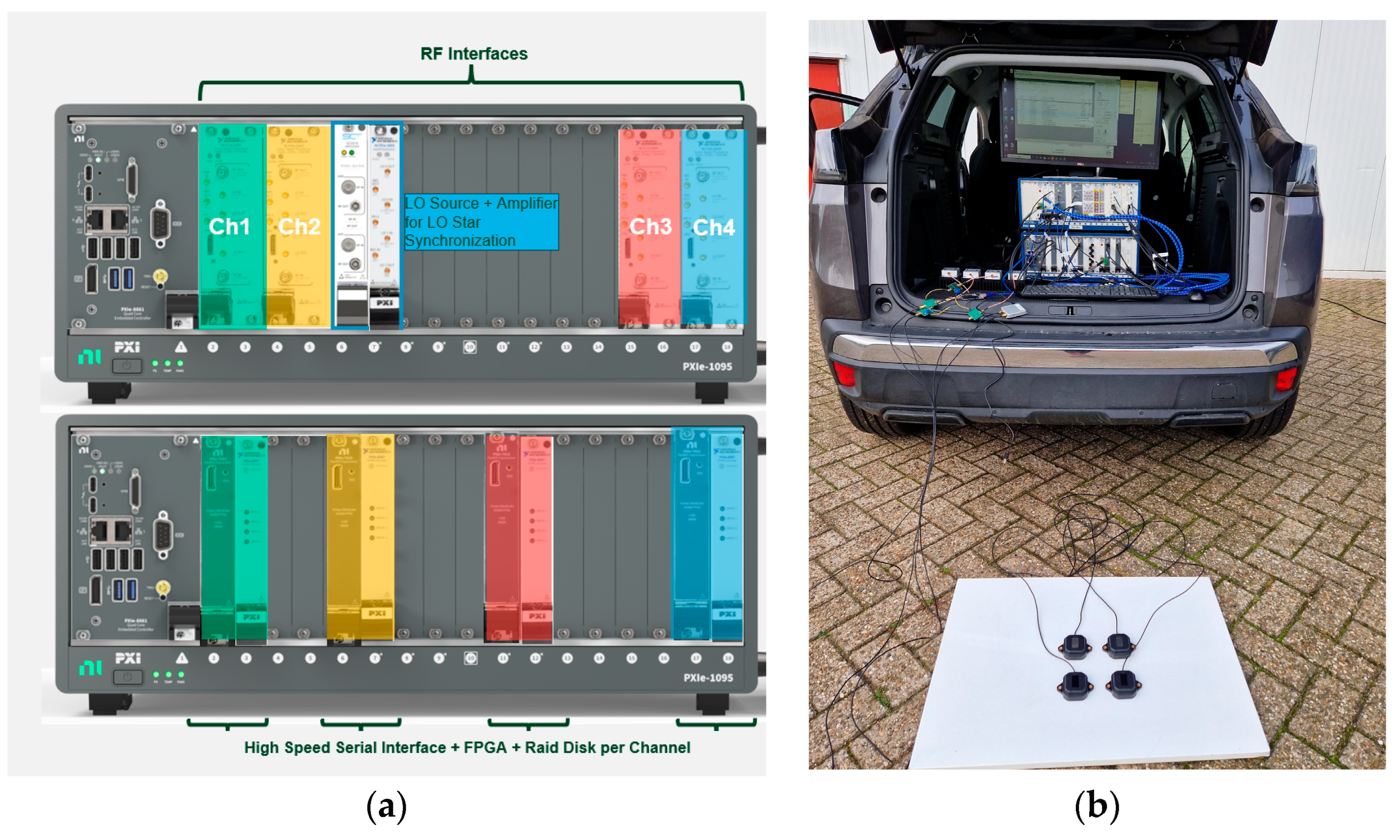
A record and playback system consisting of four synchronized Vector Signal Transceivers (VSTs) were used to generate and acquire GNSS signals on four RF ports; the local oscillators (LO) of the VSTs were shared from a common LO source to ensure the phase and amplitude coherency among the RF chains and across the recorded bandwidth, as shown in Figure 2a. The deployed VST system was connected to four antenna elements that were distributed as a square with a side length of 10 cm, as shown in Figure 2b. The recorded bandwidth, the sampling rate and the center frequency were, respectively, 32 MHz, 40 Msps, and 1575.42 MHz. A total of 5 min was recorded; however, due to the lengthy analysis using MATLAB R2024a, only the result for 1 min is shown. Furthermore, a 16 ms integration time was used during the acquisition stage, of which 4 ms period was the coherent integration.
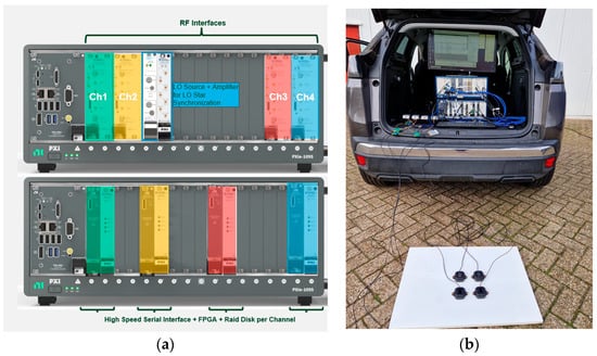
Figure 2.
The deployed 4-channel phase aligned record and playback system in the experiment. (a) hardware configuration of the setup showing the 4 channel VSTs in the upper PXI chassis and the associated FPGA cards and RAID disks in the lower chassis; (b) live test experiment using the setup connected to a rectangular antenna array, where each element is wired to a low noise amplifier (LNA) into the input of the corresponding VST.
3.2. Field Results
In this section, we present the experimental results of the proposed solution. We compared the proposed solution against the traditional single-antenna system; the first antenna of the four antennas was selected as a reference. All the signal processing was conducted offline using MATLAB implementation. In this work, we modified the Multi-GNSS SDR Receiver (FGI-GSRx), based on the guidance provided by Borre et al. [15], to include the beamforming approach. The FGI-GSRx MATLAB software is capable of offering a positioning solution with multiple GNSS signals; in our implementation, we have considered GPS L1, Galileo E1b, and BeiDou B1I signals.
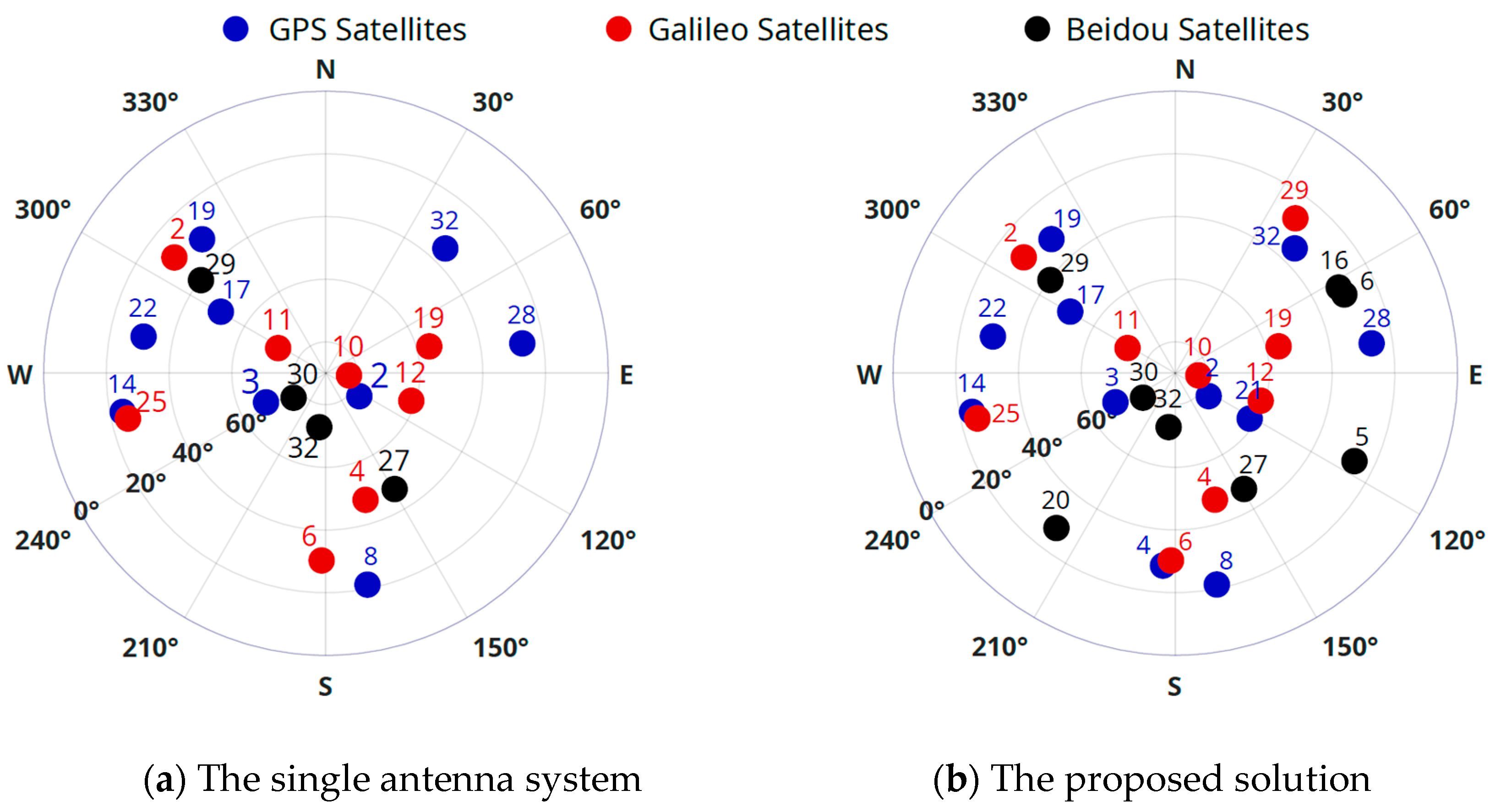
Figure 3 shows the skyplot of the acquired satellites from a single-antenna system and the proposed solution, respectively. It is clear, as expected, that the array antenna system acquired more satellites than the single-antenna system. The proposed solution has acquired 28 satellites, while the single-antenna system has only acquired 21 satellites.
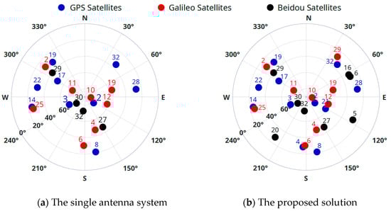
Figure 3.
Skyplot representations of the acquired satellites from both the single-antenna system and the proposed solution, respectively.
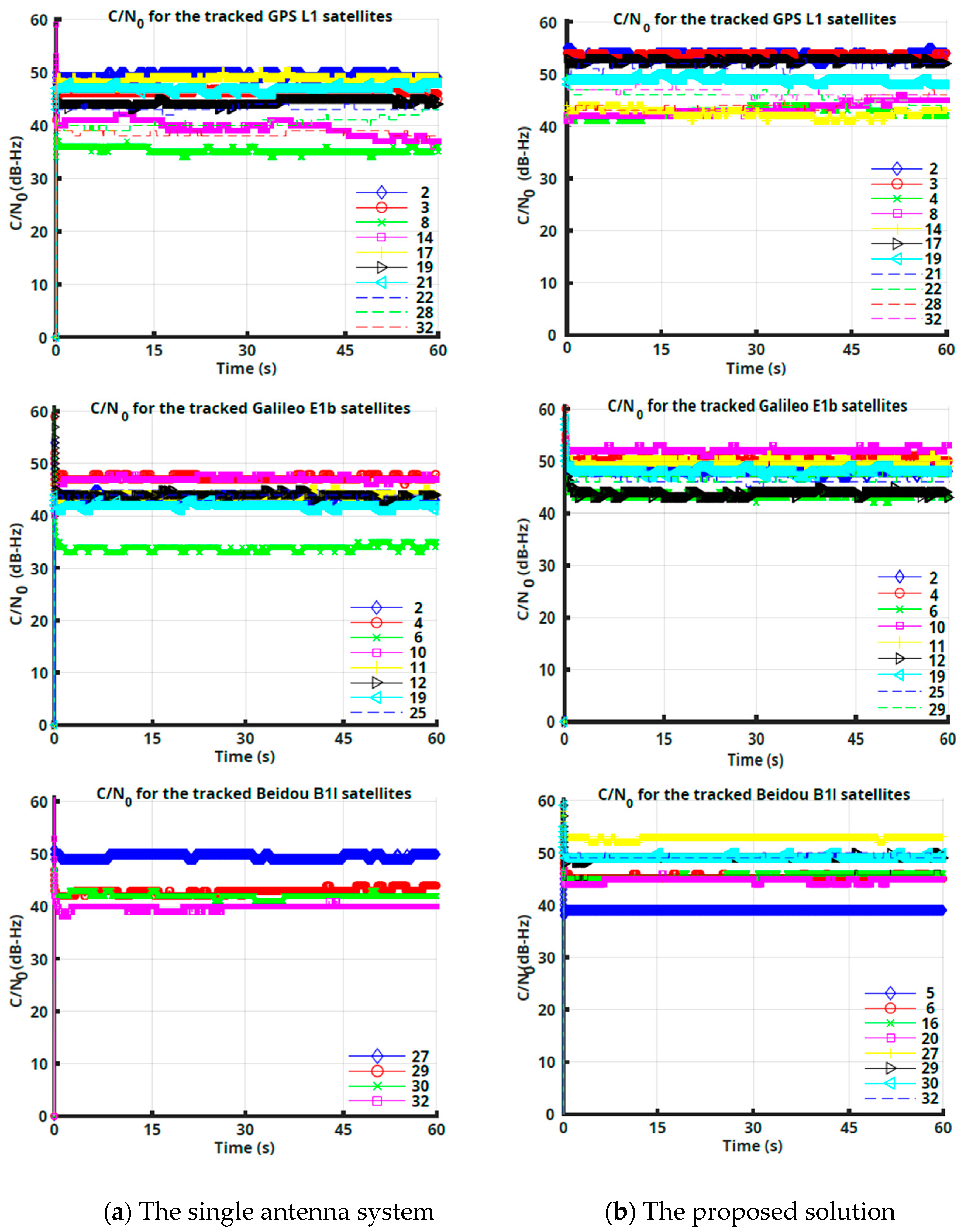
Figure 4 shows that the proposed solution provides higher CN0 estimates for all the acquired satellites, as compared to the single-antenna system. It is worth mentioning that the traditional MVDR beamformer fails to provide any valuable weight vectors. Accordingly, the traditional MVDR results were excluded due to loss of the tracking signals. This can be attributed to the presence of the multipath correlated signals and the sensitivity of the traditional MVDR to the sample size used to construct the array antenna covariance matrix; in this test, only four acquired complex samples have been exploited. Consequently, the MVDR algorithm fails to provide the correct weight vectors.
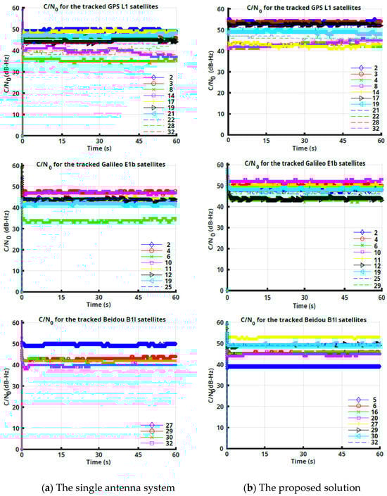
Figure 4.
CN0 values for acquired satellites. Proposed solution has acquired more satellites than single-antenna system. Furthermore, proposed technique has estimated high CN0 values for all acquired signals.
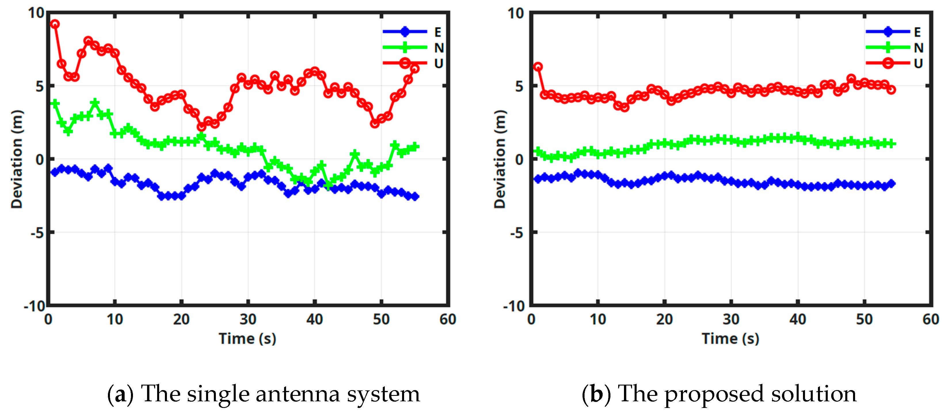
Figure 5 shows the positioning estimation error in meters for the single-antenna system and the proposed approach, respectively. The obtained positioning estimation error is presented as the deviation from the true 3D position in East (E), North (N), and Up (U) coordinates. The true reference position has been estimated using Real-time kinematic (RTK) technique. It is clear that the proposed approach has provided a more accurate estimation than the single-antenna system. The 95% 3D position error for the proposed solution and for the single-antenna system is 5.2 and 7.7 m, respectively. Furthermore, the position dilution of precision (pdop) is 0.84 for the proposed approach and 1.07 for the single-antenna system. Finally, it can be observed, from Figure 5, that the proposed solution provides a more stable estimation over time than the single-antenna system, which can be attributed to the proposed solution capability of estimating and mitigating the multipath effect.
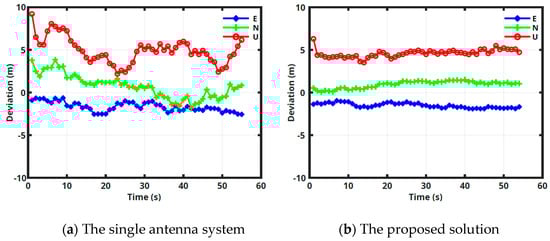
Figure 5.
Obtained positioning estimation error; the error is presented in terms of deviation from true 3D position in East (E), North (N), and Up (U).
4. Conclusions
In this paper, we have provided a robust beamforming technique using array antennas. The proposed solution constitutes two stages, the first stage exploits an array antenna system to decompose the received signals into direct and reflected signals based on the SAGE algorithm. The second stage, on the other hand, exploits the MVDR algorithm (with the decomposed and de-correlated signals) to produce the weight vector that steers the main beam towards the satellite’s direction and the nulls towards the multipath effect.
Experimental analysis was conducted in an open-sky static environment using a four-RF-port Vector Signal Transceiver (VST) system, manufactured by National Instruments (NI) as part of the ESA NAVISP program. The experimental results show a significant improvement in the estimated CN0 values, using the proposed solution, compared to a single-antenna system. Furthermore, in the experimental conditions, the traditional MVDR beamformer could not track the GNSS signals; this can be attributed to the fact that the MVDR beamforming capability deteriorates with the presence of multipath effect and the low sample size of the received signals that are used to construct the array antenna covariance matrix.
Author Contributions
Conceptualization, N.B.; methodology, N.B.; software, N.B.; validation, N.B., S.C. and S.B.; formal analysis, N.B.; investigation, N.B.; resources, N.B.; data curation, N.B.; writing—original draft preparation, N.B.; writing—review and editing, N.B., S.C., S.B., R.F. and P.C.; visualization, N.B.; supervision, N.B.; project administration, R.F.; funding acquisition, R.F. All authors have read and agreed to the published version of the manuscript.
Funding
This research was funded by the European Space Agency (ESA) Navigation Innovation and Support Program (NAVISP).
Institutional Review Board Statement
Not applicable.
Informed Consent Statement
Not applicable.
Data Availability Statement
Data are contained within the article. The content of the present article reflects solely the authors’ view and by no means represents the official ESA view.
Conflicts of Interest
Author Samah Chazbeck, Szabolcs Berki and Raffaele Fiengo were employed by the company National Instruments. The remaining authors declare that the research was conducted in the absence of any commercial or financial relationships that could be construed as a potential conflict of interest.
References
- Groves, P.D.; Zhong, Q.; Faragher, R.; Esteves, P. Combining inertially-aided extended coherent integration (supercorrelation) with 3D-mapping-aided GNSS. In Proceedings of the 33rd International Technical Meeting of the Satellite Division of The Institute of Navigation (ION GNSS+ 2020), Online, 22–25 September 2020; pp. 2327–2346. [Google Scholar]
- Park, K.; Seo, J. Single-antenna-based GPS antijamming method exploiting polarization diversity. IEEE Trans. Aerosp. Electron. Syst. 2020, 57, 919–934. [Google Scholar] [CrossRef]
- BniLam, N.; Principe, F.; Crosta, P. Large Array Antenna Aperture for GNSS Applications. IEEE Trans. Aerosp. Electron. Syst. 2023, 60, 675–684. [Google Scholar] [CrossRef]
- Seco-Granados, G.; Fernandez-Rubio, J.; Fernandez-Prades, C. ML estimator and hybrid beamformer for multipath and interference mitigation in GNSS receivers. IEEE Trans. Signal Process. 2005, 53, 1194–1208. [Google Scholar] [CrossRef]
- Fernández-Prades, C.; Arribas, J.; Closas, P. Robust GNSS receivers by array signal processing: Theory and implementation. Proc. IEEE 2016, 104, 1207–1220. [Google Scholar] [CrossRef]
- Bni Lam, N.H. Angle of Arrival Estimation for Low Power and Long Range Communication Networks. Doctoral Dissertation, University of Antwerp, Antwerpen, Belgium, 2021. [Google Scholar]
- Florio, A.; BniLam, N.; Talarico, C.; Crosta, P.; Avitabile, G.; Coviello, G. LEO-based Coarse Positioning through Angle-of-Arrival Estimation of Signals of Opportunity. IEEE Access 2024, 12, 17446–17459. [Google Scholar] [CrossRef]
- Bnilam, N.; Joosens, D.; Berkvens, R.; Steckel, J.; Weyn, M. AoA-based localization system using a single IoT gateway: An application for smart pedestrian crossing. IEEE Access 2021, 9, 13532–13541. [Google Scholar] [CrossRef]
- Bnilam, N.; Tanghe, E.; Steckel, J.; Joseph, W.; Weyn, M. ANGLE: ANGular location estimation algorithms. IEEE Access 2020, 8, 14620–14629. [Google Scholar] [CrossRef]
- BniLam, N.; Steckel, J.; Weyn, M. Synchronization of multiple independent subarray antennas: An application for angle of arrival estimation. IEEE Trans. Antennas Propag. 2018, 67, 1223–1232. [Google Scholar] [CrossRef]
- BniLam, N.; Joosens, D.; Aernouts, M.; Steckel, J.; Weyn, M. LoRay: AoA estimation system for long range communication networks. IEEE Trans. Wirel. Commun. 2020, 20, 2005–2018. [Google Scholar] [CrossRef]
- BniLam, N.; Janssens, R.; Steckel, J.; Weyn, M. AoA estimates for LPWAN technologies: Indoor experimental analysis. In Proceedings of the 2021 15th European Conference on Antennas and Propagation (EuCAP)’, Dusseldorf, Germany, 22–26 March 2021; pp. 1–5. [Google Scholar]
- BniLam, N.; Ergeerts, G.; Subotic, D.; Steckel, J.; Weyn, M. Adaptive probabilistic model using angle of arrival estimation for IoT indoor localization. In Proceedings of the 2017 International Conference on Indoor Positioning and Indoor Navigation (IPIN), Sapporo, Japan, 18–21 September 2017; pp. 1–7. [Google Scholar]
- Fleury, B.H.; Tschudin, M.; Heddergott, R.; Dahlhaus, D.; Pedersen, K.I. Channel parameter estimation in mobile radio environments using the SAGE algorithm. IEEE J. Sel. Areas Commun. 1999, 17, 434–450. [Google Scholar] [CrossRef]
- Borre, K.; Fernández-Hernández, I.; López-Salcedo, J.A.; Bhuiyan, M.Z.H. (Eds.) GNSS Software Receivers; Cambridge University Press: Cambridge, UK, 2022. [Google Scholar]
Disclaimer/Publisher’s Note: The statements, opinions and data contained in all publications are solely those of the individual author(s) and contributor(s) and not of MDPI and/or the editor(s). MDPI and/or the editor(s) disclaim responsibility for any injury to people or property resulting from any ideas, methods, instructions or products referred to in the content. |
© 2025 by the authors. Licensee MDPI, Basel, Switzerland. This article is an open access article distributed under the terms and conditions of the Creative Commons Attribution (CC BY) license (https://creativecommons.org/licenses/by/4.0/).