Proceeding Paper

Advanced Virtual Synchronous Generator Control Scheme for Improved Power Delivery in Renewable Energy Microgrids †

by
Mandarapu Srikanth
1,
Yellapragada Venkata Pavan Kumar
2,* and
Sivakavi Naga Venkata Bramareswara Rao
3
1
Department of Electrical and Electronics Engineering, Raghu Engineering College, Dakamarri, Visakhapatnam 531162, Andhra Pradesh, India
2
School of Electronics Engineering, VIT-AP University, Amaravati 522241, Andhra Pradesh, India
3
Department of Electrical and Electronics Engineering, Sir C. R. Reddy College of Engineering, Eluru 534007, Andhra Pradesh, India
*
Author to whom correspondence should be addressed.
Presented at the 5th International Electronic Conference on Applied Sciences, 4–6 December 2024; https://sciforum.net/event/ASEC2024.
Eng. Proc. 2025, 87(1), 60; https://doi.org/10.3390/engproc2025087060
Published: 30 April 2025
(This article belongs to the Proceedings of The 5th International Electronic Conference on Applied Sciences)

Abstract

:
Renewable energy and voltage source inverter-driven microgrids generally lack natural inertia to provide transient energy support during sudden load demands. To address this, the virtual synchronous generator (VSG) is a state-of-the-art control technique applied in power controllers to emulate virtual inertia during sudden load changes. This allows for stable power delivery from the source to the loads during sudden active power load demands. However, in systems with large inductively dominant load demands, conventional VSG-based power controllers may exhibit a delayed reactive power response due to their inertia-emulating characteristics, potentially affecting the overall power-sharing performance. To address this limitation of VSG control, this paper proposes an advanced control scheme in which the VSG is supported by appropriately designed voltage and current controllers. Conventionally, classical tuning techniques are used to design the controllers in the forward paths of the voltage and current controllers (CVAs). Thus, the conventional control scheme is a combination of a VSG and CVAs. Recently, a hybrid modified pole-zero cancellation technique has been discussed in the literature for the design of voltage and current controllers (HVAs) to improve the vector control of the inverter. This method supports better tuning for controllers of both forward and cross-coupling paths. Therefore, to improve the power delivery with VSG-based control when subjected to inductive load changes, this paper proposes an advanced control scheme that is based on the combination of VSG and HVA. The performance of both conventional and proposed control schemes is verified through simulation in MATLAB/Simulink under two different test load conditions, namely good and poor power factor loadings. Based on the results obtained during these test cases, the response and power delivery capability of the proposed control scheme is comparable with that of the conventional control scheme. The results verify that the power delivery capability of the microgrid with the proposed control scheme is improved by 25% compared to the conventional control scheme.

1. Introduction

Environmental and financial constraints have motivated the need to replace conventional synchronous generator-based power plants with distributed energy-based microgrids [1,2]. These microgrids are generally driven by a power electronic-based voltage source inverter through suitable control logic [3]. However, the main setback of these microgrids is their inability to mimic the inertia characteristics of conventional synchronous generators [4,5]. A virtual synchronous generator (VSG) is a state-of-the-art control technique applied in power controllers to emulate virtual inertia during sudden load changes in microgrids [6]. This VSG control logic is used at the power controller level, which is further supported by inner voltage and current (VA) control loops [7,8]. The role of VSGs toward frequency regulation in the case of active power load changes has been widely studied in the literature [9]. Conventionally, the power-handling capability is improved through the adjustment of inertia and damping coefficients of traditional VSG logic [10,11]. While VSG control techniques effectively emulate the dynamic behavior of synchronous machines, their response to inductively dominant loads may be limited in terms of reactive power compensation. This is primarily due to the VSG’s reliance on frequency and phase angle dynamics, which govern active power flow but do not directly control reactive power unless supplemented by additional voltage or current control loops. However, these techniques offer limited improvement in power delivery. To overcome this limitation, a modified VSG (MVSG), based on designing the governor gain constant, was discussed [12]. In the study, the emphasis was on improving the power delivery response under active power-type load switching, which is less common than inductively dominant reactive-type load switching. This provided the necessary motivation to enhance the power delivery capability of traditional VSG/MVSG-based microgrids under inductively dominant load switching. MVSG cascaded with improved VA control loops were discussed in [13]. From this, it is understood that improved VA control loops will also enhance the power delivery of MVSG-based microgrids in the case of inductively dominant load switching. Improvements to VA control loops are implemented either through advanced tuning [14] or through structural modifications [15]. Recently, a hybrid method (HVA) that incorporated both advanced tuning and structural modifications for VA control loops was discussed [16]. Therefore, it is clear that the power delivery of MVSG-based microgrids is achieved with support from advanced VA controllers.
Very few works have focused on enhancing the power delivery capability of traditional VSG-based microgrids through support from improved VA control loops. Improved VA control loops whose controllers were tuned based on parametric sensitivities of eigenvalues and cascaded with traditional VSGs were studied in [17]. This method falls under the category of effective tuning of controllers, while the method discussed in [16] incorporates both tuning improvements and structural modifications. These studies led to the identification of a research gap, highlighting the need to study the role of advanced VA controllers in the power delivery capability of traditional VSG-driven microgrids. Therefore, to further address the issue discussed in the aforementioned research gap, this paper proposes a traditional VSG cascaded with HVA. Therefore, the novelty of our work lies not in the reinvention of HVA but in its strategic integration with a VSG-based control scheme for a renewable energy microgrid, along with a systematic evaluation under dynamic load conditions.
The remaining sections of the paper are organized as follows. Section 2 describes the implementation of the proposed methodology. The results obtained from the proposed control method and a corresponding discussion based on these results are presented in Section 3. The conclusions, along with limitations and possible future directions of this proposed work, are outlined in Section 4.

2. Proposed Methodology

A block diagram that helps to compare and identify the differences between the conventional and proposed control methodologies of this research is shown in Figure 1. Traditional VSG control logic is used for the active power controller of both the conventional and proposed methodologies. The conventional VA (CVA) control loops of the conventional methodology employ proportional–integral (PI) controllers in the forward paths, whose values are tuned based on [17], whereas the HVA control loops of the proposed methodology are developed based on the hybrid modified pole-zero cancellation (HMPZC) method as discussed in [16]. Hereafter, the conventional methodology will be referred to as VSG-CVA and the proposed methodology as VSG-HVA in this paper.

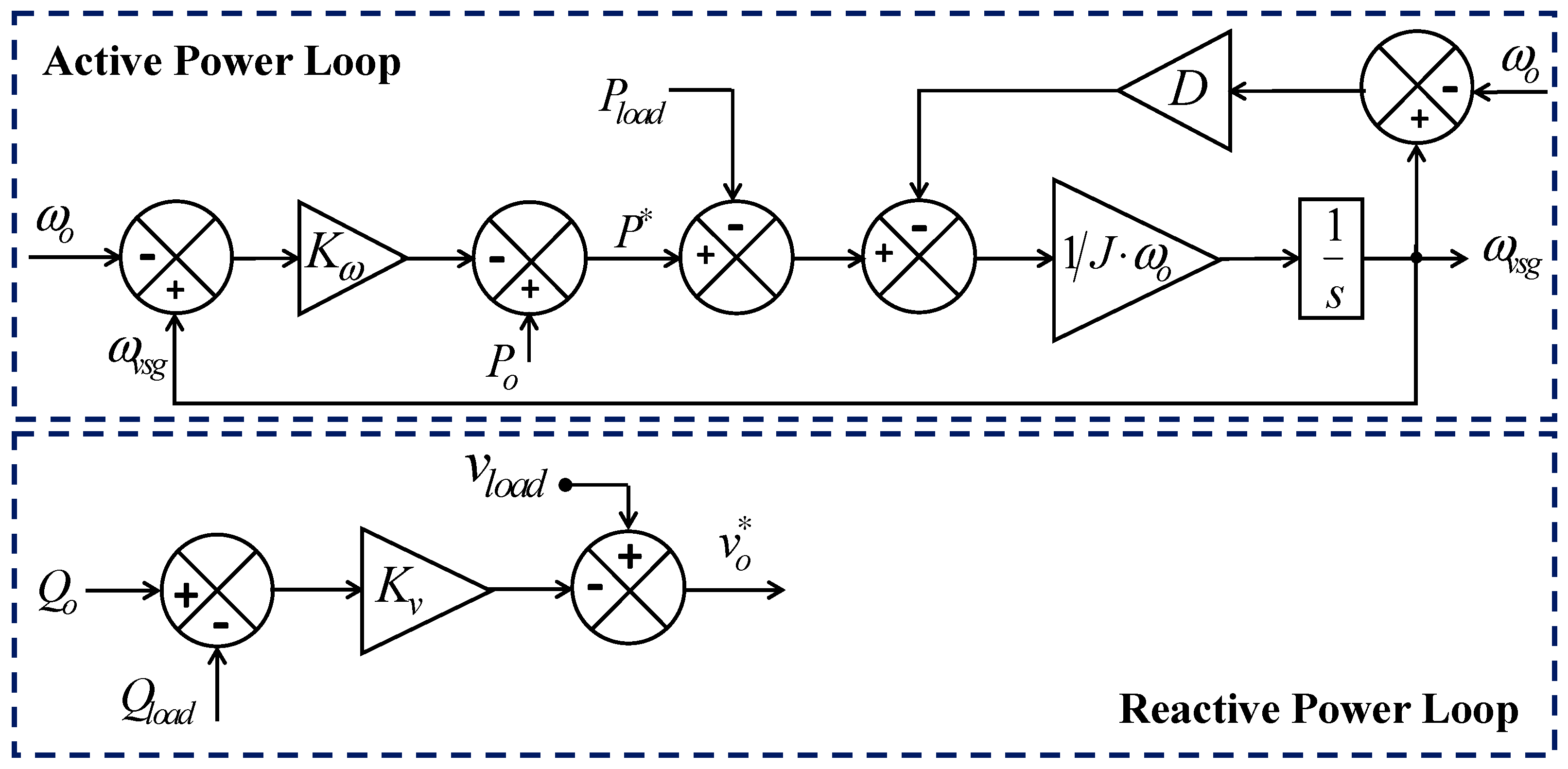
2.1. Power Control Loops

The VSG-based active and reactive power control loops are shown in Figure 2. Active power is derived from the swing equation of the conventional synchronous generator to emulate virtual inertia. The difference between the nominal frequency ω0 and the output frequency of the VSG ωvsg is processed through the speed governor gain constant Kω. To this, the nominal active power P0 is added, resulting in active power reference P*. Assuming a lossless system, the power delivered to the load Pload is the power generated. Therefore, the difference between P* and Pload is processed through the inertia constant J and the damping coefficient D.
Similarly, the reactive power loop generates the voltage reference. This control loop helps the load voltage follow the reference voltage based on the difference between the reference and nominal reactive powers. This difference is processed through the reactive power–voltage droop gain logic.

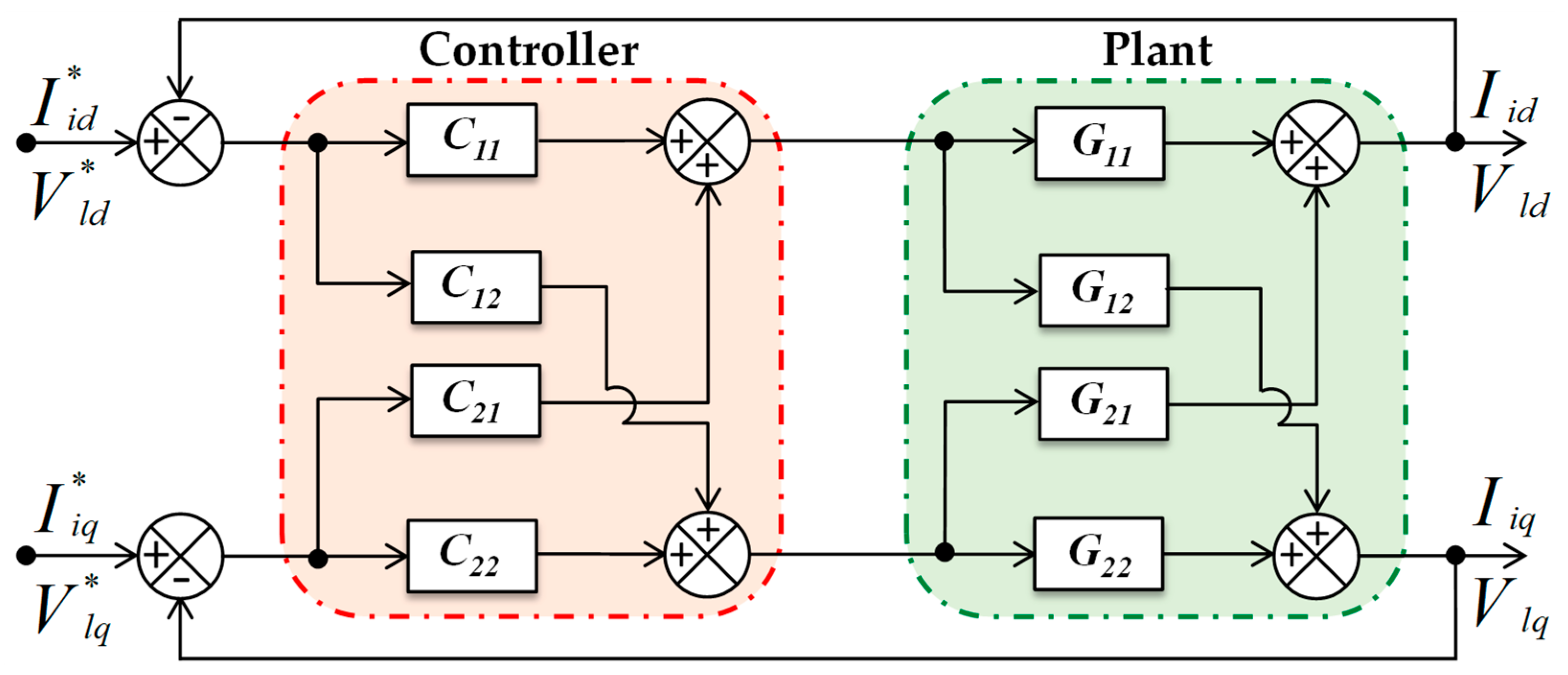
2.2. Hybrid Voltage and Current Control Loops (HVAs)

A generic block diagram for the design of VA control loops is shown in Figure 3. In both cases of designing a voltage control loop and a current control loop, the plant model can be viewed as a two-input, two-output (TITO) system, with G11 and G22 representing plant transfer functions in the forward paths, while G12 and G21 represent plant transfer functions in the cross paths. To provide a better response without the need for a separate decoupler, the controller model that is employed in the proposed work can be seen in this figure. In Figure 3, C11 and C22 are controllers in the forward paths, while C12 and C21 are controllers in the cross paths. In HVA, C11/C22 are tuned using advanced tuning techniques and avoid the need for a derivative in the controller. In the case of conventional methods, C12/C21 are simple proportional gain controllers with very little decoupling capability. In contrast, in HVA, C12/C21 are designed as PI controllers, whose values are obtained through the internal model control principle.

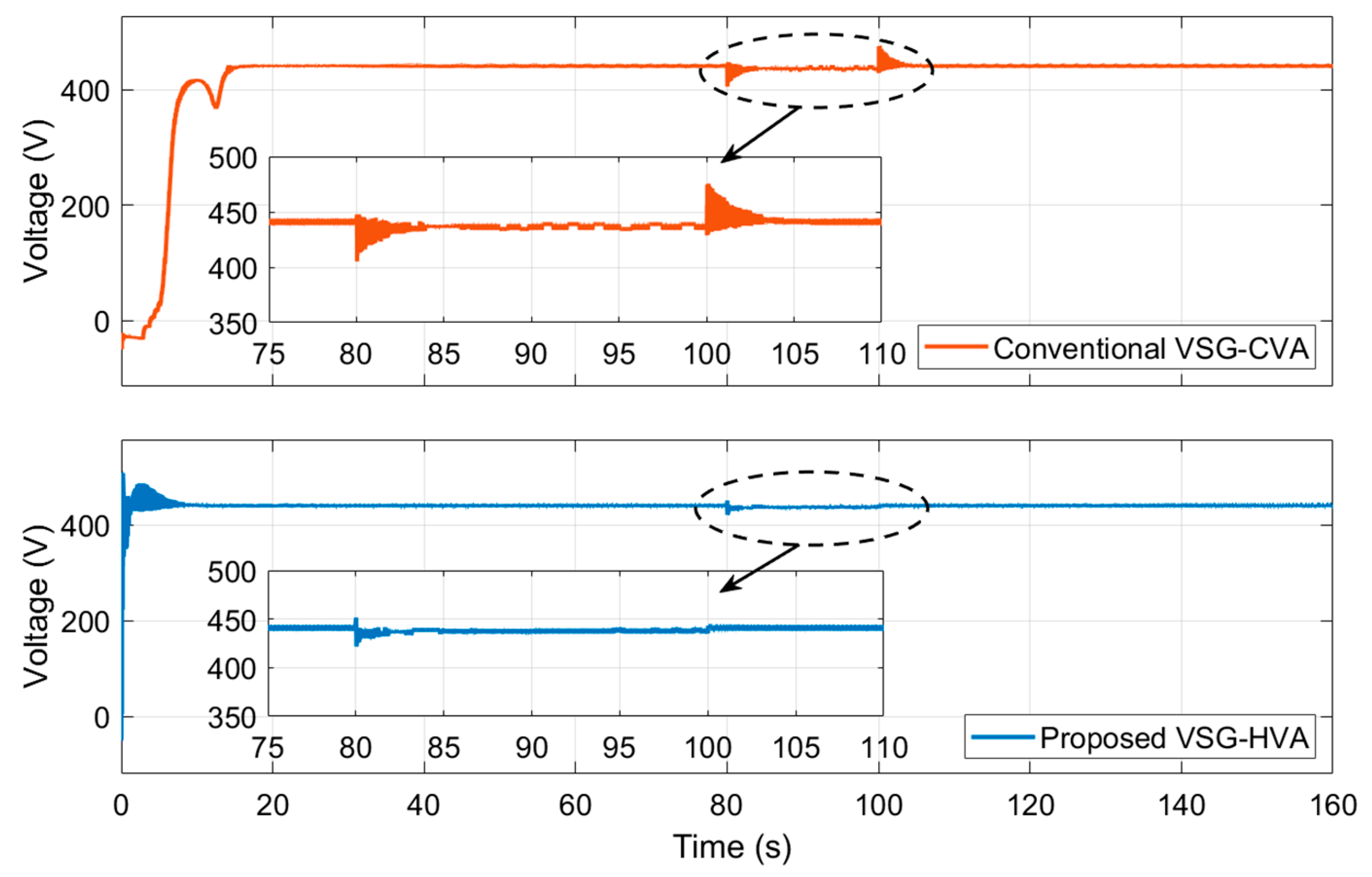
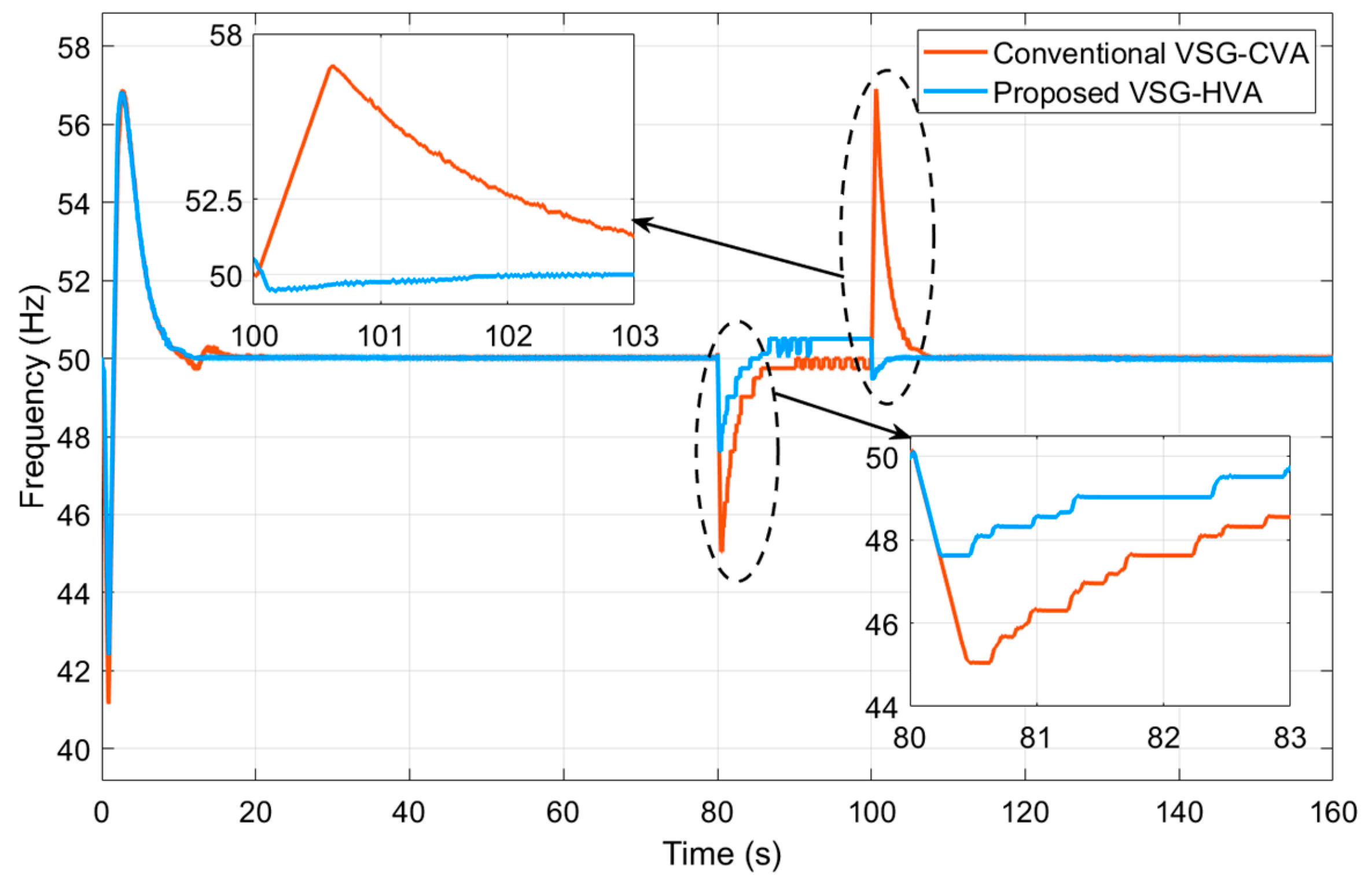
3. Results and Discussion

The test setup consisted of a single voltage source inverter-regulated distributed energy resource that fed two loads. The inverter received the necessary gate pulse based on the decisions from the controller. The simulation was conducted for 160 s, during which sudden inductive load switching was implemented at the 80th s and 90th s. Three different test cases, T1, T2, and T3, were designed to verify the efficacy of the proposed method. Commonly, in all the test cases, the resistive and inductive components of the first load were the same. Similarly, the resistive component of the second load was also the same in all test cases. But the inductive component of the second load was different in each of the test cases. In test case T1, its value was 3 kVar; in T2, the value was 7.5 kVar; and in T3, the value was 10 kVar.

3.1. Evaluation Criterion

The results of the proposed control methodology were compared with those of the conventional methodology with respect to frequency and voltage. VSG control-based schemes generally suffer from large deviations in the frequency and magnitude of voltage when subjected to sudden load changes [18]. These deviations are treated by the frequency and voltage relays as an indication of a true fault, which eventually leads to unnecessary tripping and loss of power delivery from the microgrid. Therefore, the nuisance tripping criterion was used in this work for evaluating the frequency and voltage results of the conventional and proposed control methodologies. This criterion involves magnitude and time conditions. First, the magnitude condition was verified, and if its condition was violated, then the time condition was checked. In case the time condition was also violated, a nuisance trip occurred. A control scheme that does not prevent the occurrence of a nuisance trip will eventually fail to deliver the power and is, therefore, considered inferior. In this work, the magnitude condition was fixed as ±5%, and the time condition as 1 s for both the frequency and voltage [19]. Accordingly, the allowable margin, which was defined as the magnitude condition for the frequency, ranged from 47.5 Hz to 52.5 Hz and from 418 V to 462 V for the voltage. When the deviation in frequency or voltage crossed either the upper limit or lower limits, the tripping action was initiated and the time measurement began. When this deviation returned to inside the allowable margin before 1 s of time measurement, the tripping action was suspended or tripping occurred.

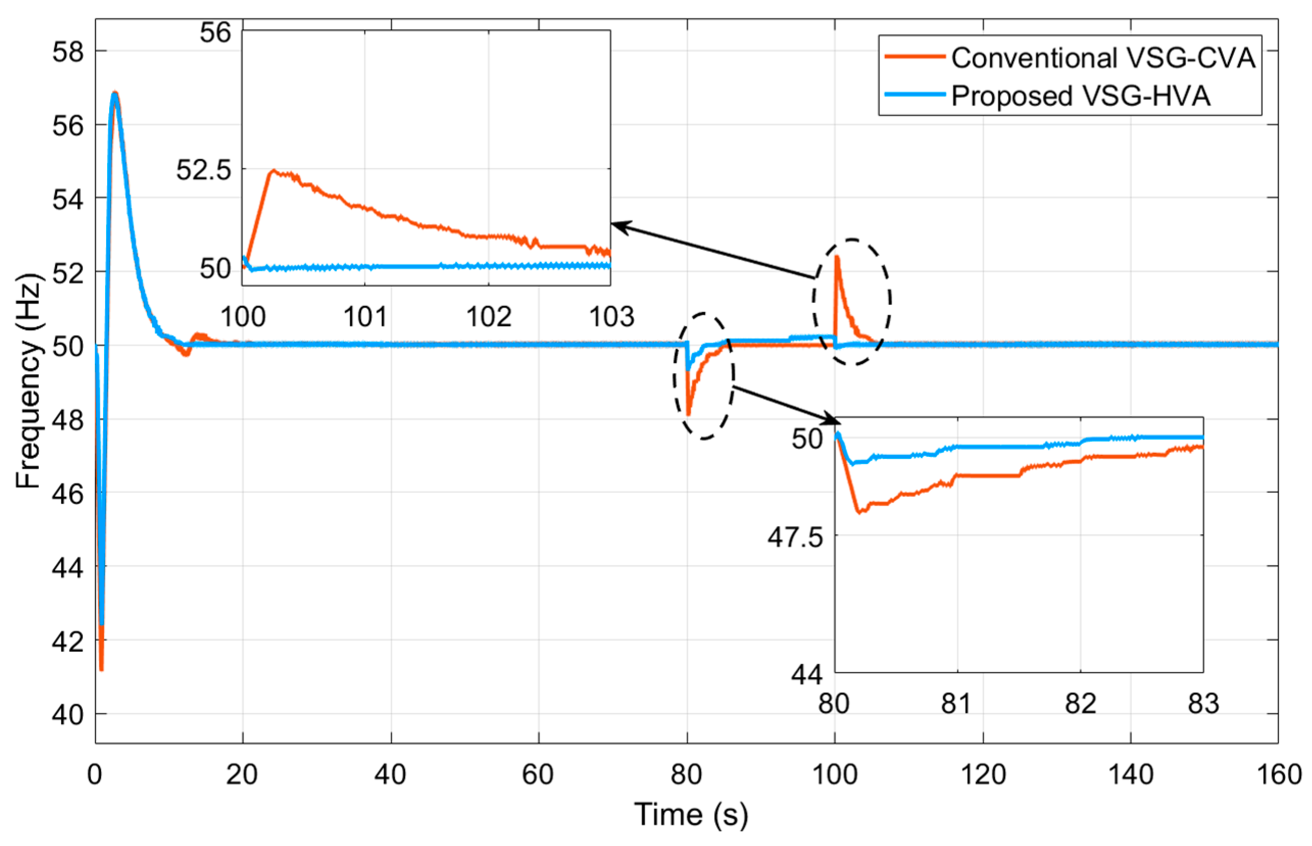
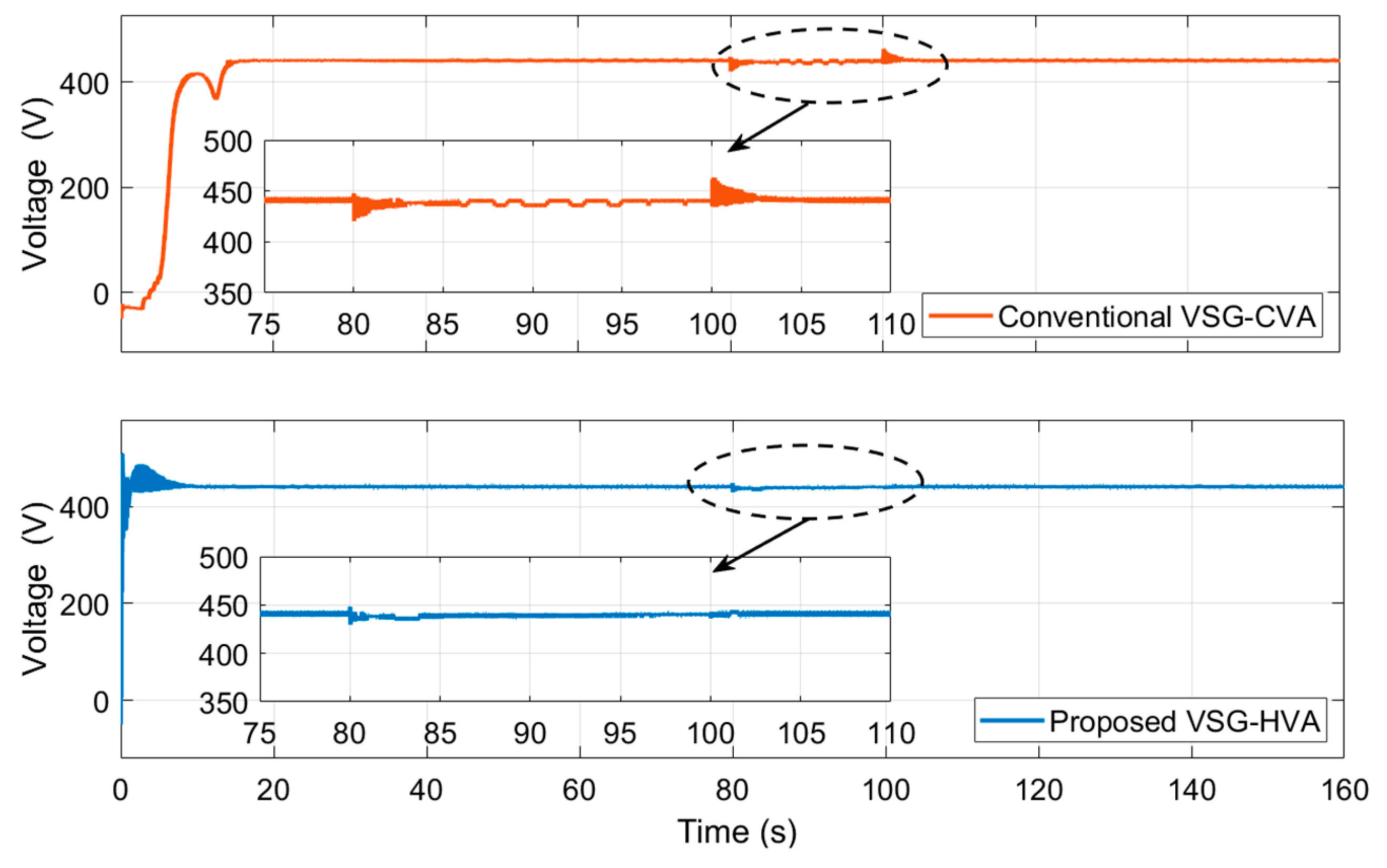
3.2. Test Case 1 (T1)

The frequency and voltage results with the conventional and proposed method during test case T1 are shown in Figure 4 and Figure 5, respectively. From the frequency results shown in Figure 4, it can be observed that the load switching at 80 s caused undershoots of 1.5 Hz and 0.63 Hz with the conventional and the proposed methods, respectively. Similarly, the load switching at 100 s caused overshoots of 2.5 Hz and 0.05 Hz with the conventional and the proposed methods, respectively. As all these values were within the tolerance limits, the magnitude condition was not violated either during load switch ON or switch OFF. From the voltage result, as shown in Figure 5, it can be observed that the load switching at 80 s caused undershoots of 3.91% and 1.95% with the conventional and the proposed methods, respectively.
As both these values were within the tolerance band, the magnitude condition was not violated. However, the load switching at 100 s caused overshoots of 6.12% and 0.35% with the conventional and the proposed methods, respectively. Therefore, during this test case, the magnitude condition was violated with the conventional method only. But this deviation returned to within the tolerance band in 0.2 s, which avoided tripping, thereby ensuring power delivery. The proposed method with a deviation of 1.95% under load switch ON and 0.35% under load switch OFF remained within the tolerable limits, thus not violating the magnitude condition.

3.3. Test Case 2 (T2)

The frequency and voltage results with the conventional and proposed methods during test case T2 are shown in Figure 6 and Figure 7, respectively.
As shown in the frequency results in Figure 6, load switching at 80 s caused undershoots of 3.1 Hz and 1.25 Hz with the conventional and the proposed methods, respectively. Similarly, the load switching at 100 s caused overshoots of 4.2 Hz and 0.1 Hz, with the conventional and the proposed methods, respectively. In both situations, the magnitude condition was violated with the conventional method. However, as the settling times were 0.29 s and 0.817 s under load switch ON and OFF, respectively, the time condition was not violated with the conventional method with respect to frequency.
As shown in the voltage results in Figure 7, load switching at 80 s caused undershoots of 8.01% and 3.12% with the conventional and the proposed methods, respectively. Similarly, the load switching at 100 s caused overshoots of 8.16% and 0.49% with the conventional and the proposed methods, respectively. Therefore, the magnitude condition was violated with the conventional method only. However, as the settling times with the conventional method were 0.35 s and 0.6 s under load switch ON and switch OFF, respectively, the time condition was not violated.

3.4. Test Case 3 (T3)

The frequency and voltage results with the conventional and proposed methods during test case T3 are shown in Figure 8 and Figure 9, respectively. As shown in the frequency results in Figure 8, load switching at 80 s caused undershoots of 4.96 Hz and 2.39 Hz with the conventional and the proposed methods, respectively. Similarly, load switching at 100 s caused overshoots of 6.9 Hz and 0.48 Hz with the conventional and the proposed methods, respectively. Therefore, in both situations, the magnitude condition was violated with the conventional method. For load switching at 80 s, as the settling time was 0.57 s, the time condition was not violated. However, in the case of load switching at 100 s, as the settling time was 1.846 s, the time condition was violated, eventually leading to tripping due to the frequency when the conventional method was used.
As shown in the voltage results in Figure 9, load switching at 80 s caused undershoots of 15.13% and 6.05% with the conventional and the proposed methods, respectively. Therefore, the magnitude condition was violated by both methods. However, based on the time condition, the settling times were 1.34 s and 0.31 s with the conventional and proposed methods, respectively. Therefore, the time condition was violated in the case of the conventional method but not with the proposed method. On the other hand, the load switching at 100 s caused overshoots of 15.13% and 0.95% with the conventional and the proposed methods, respectively. Therefore, the magnitude condition was violated with the conventional method only. With the settling time of 1.2 s, the time condition was violated, leading to tripping and loss of power.
A summary of the comparison between the conventional and proposed methods with respect to the frequency and voltage results under various test cases is presented in Table 1. The terms ‘deviation’ and ‘time’ under the condition column of this table relate to the magnitude condition and time condition, respectively.

4. Conclusions

This paper focused on enhancing the power delivery capability of traditional VSG-based microgrids through the support of improved VA control loops under inductively dominant load-switching conditions. Accordingly, this paper implemented the VSG-HVA control method.
The two control schemes were tested under three test cases, T1, T2, and T3. The frequency and voltage results that were obtained during these test cases were carefully evaluated using nuisance tripping as the criterion. From the highest loading conditions, deploying the conventional method resulted in settling times of 1.846 s in frequency and 1.2 s in voltage, whereas the proposed VSG-HVA method successfully prevented the occurrence of any nuisance trip, thus contributing to a 25% improvement in power delivery. Finally, this work concludes that the proposed VSG-HVA method can enhance the power delivery capability of microgrids.

4.1. Limitation

Based on the frequency plot of test case T3 (Figure 8), the proposed method resulted in a steady error from 80 to 100 s. This highlights the need for extra compensation. It was observed that the HVA control scheme exhibited a small steady-state error in voltage regulation under certain load conditions. This behavior is attributed to the absence of an explicit integral component in the voltage control loop. The HVA method, in its current form, prioritizes dynamic response by relying on coordinated voltage and current feedback, which improves transient performance but may not fully eliminate steady-state offsets. Additionally, the tuning of proportional control gains in HVA was optimized for fast response rather than precision at a steady state. This trade-off is a known characteristic of hybrid control schemes, where responsiveness is favored over accuracy in steady-state scenarios. Future enhancements can include the integration of an adaptive or PI-based compensator to improve steady-state accuracy without compromising dynamic performance.

4.2. Future Scope

The present work focused on the development and analysis of an HVA control technique aimed at achieving effective power sharing and dynamic load-following capability in renewable energy microgrids. While the proposed technique is derived from virtual synchronous generator (VSG) principles, this study specifically limited its application to scenarios involving varying load demands and did not explore other potential benefits of VSG-based control, such as transient stability enhancement during electrical faults, grid voltage support, or harmonic compensation. These aspects, although beyond the scope of the current study, are recognized as important performance metrics in practical grid-connected systems. The inherent inertia-mimicking behavior of the HVA technique suggests its potential to positively influence system stability and voltage regulation. Future research will be directed toward evaluating the performance of the HVA controller under fault disturbances, weak grid conditions, and harmonically distorted environments, thereby broadening its applicability and robustness in real-world microgrid operations.

Author Contributions

Conceptualization: M.S.; methodology: Y.V.P.K.; software: Y.V.P.K.; formal analysis: M.S.; investigation: M.S.; resources: Y.V.P.K.; data curation: M.S. and Y.V.P.K.; supervision: Y.V.P.K. and S.N.V.B.R.; validation: S.N.V.B.R.; visualization: M.S.; project administration: Y.V.P.K.; writing—original draft: M.S.; writing—review and editing: Y.V.P.K. and S.N.V.B.R. All authors have read and agreed to the published version of the manuscript.

Funding

This research received no external funding.

Institutional Review Board Statement

Not applicable.

Informed Consent Statement

Not applicable.

Data Availability Statement

The original contributions presented in this study are included in the article. Further inquiries can be directed to the corresponding authors.

Conflicts of Interest

The authors declare no conflicts of interest.

References

  1. Salam, I.U.; Yousif, M.; Numan, M.; Billah, M. Addressing the Challenge of Climate Change: The Role of Microgrids in Fostering a Sustainable Future—A Comprehensive Review. Renew. Energy Focus 2024, 48, 100538. [Google Scholar] [CrossRef]
  2. Peter, N.; Gupta, P.; Goel, N. Intelligent strategies for microgrid protection: A comprehensive review. Appl. Energy 2025, 379, 124901. [Google Scholar] [CrossRef]
  3. Alipoor, J.; Miura, Y.; Ise, T. Stability Assessment and Optimization Methods for Microgrid with Multiple VSG Units. IEEE Trans. Smart Grid 2018, 9, 1462–1471. [Google Scholar] [CrossRef]
  4. Guan, M.; Pan, W.; Zhang, J.; Hao, Q.; Cheng, J.; Zheng, X. Synchronous Generator Emulation Control Strategy for Voltage Source Converter (VSC) Stations. IEEE Trans. Power Syst. 2015, 30, 3093–3101. [Google Scholar] [CrossRef]
  5. Dheer, D.K.; Soni, N.; Doolla, S. Improvement of Small Signal Stability Margin and Transient Response in Inverter-Dominated Microgrids. Sustain. Energy Grids Netw. 2016, 5, 135–147. [Google Scholar]
  6. Srikanth, M.; Kumar, Y.V.P.; Amir, M.; Mishra, S.; Iqbal, A. Improvement of Transient Performance in Microgrids: Comprehensive Review on Approaches and Methods for Converter Control and Route of Grid Stability. IEEE Open J. Ind. Electron. Soc. 2023, 4, 534–572. [Google Scholar] [CrossRef]
  7. Zhao, H.; Yang, Q.; Zeng, H. Multi-loop virtual synchronous generator control of inverter-based DGs under microgrid dynamics. IET Gener. Transm. Distrib. 2017, 11, 795–803. [Google Scholar] [CrossRef]
  8. Wu, H.; Ruan, X.; Yang, D.; Chen, X.; Zhao, W.; Lv, Z.; Zhong, Q.-C. Small-Signal Modeling and Parameters Design for Virtual Synchronous Generators. IEEE Trans. Ind. Electron. 2016, 63, 4292–4303. [Google Scholar] [CrossRef]
  9. Alipoor, J.; Miura, Y.; Ise, T. Power System Stabilization Using Virtual Synchronous Generator with Alternating Moment of Inertia. IEEE J. Emerg. Sel. Top. Power Electron. 2015, 3, 451–458. [Google Scholar] [CrossRef]
  10. Ur Rehman, H.; Yan, X.; Abdelbaky, M.A.; Ullah Jan, M.; Iqbal, S. An advanced virtual synchronous generator control technique for frequency regulation of grid-connected PV system. Int. J. Electr. Power Energy Syst. 2021, 125, 106440. [Google Scholar] [CrossRef]
  11. Kerdphol, T.; Rahman, F.S.; Watanabe, M.; Mitani, Y.; Turschner, D.; Beck, H.P. Enhanced Virtual Inertia Control Based on Derivative Technique to Emulate Simultaneous Inertia and Damping Properties for Microgrid Frequency Regulation. IEEE Access 2019, 7, 14422–14433. [Google Scholar] [CrossRef]
  12. Srikanth, M.; Kumar, Y.V.P. Improved Virtual Synchronous Generator-Based Control Scheme for Enhanced Transient Response in Microgrids. Eng. Proc. 2023, 56, 4. [Google Scholar] [CrossRef]
  13. Srikanth, M.; Venkata Pavan Kumar, Y. Empowered Virtual Synchronous Generator Based Control Scheme for Improved Transient Response and Reduced Nuisance Tripping in Stable Microgrids. IEEE Access 2024, 12, 99968–99988. [Google Scholar] [CrossRef]
  14. Pavan Kumar, Y.V.; Bhimasingu, R. Design of Voltage and Current Controller Parameters Using Small Signal Model-Based Pole-Zero Cancellation Method for Improved Transient Response in Microgrids. SN Appl. Sci. 2021, 3, 836. [Google Scholar] [CrossRef]
  15. Srikanth, M.; Venkata Pavan Kumar, Y. State machine and internal model control-based hybrid controller for improved transient performance of microgrids. Energy Rep. 2024, 12, 5300–5319. [Google Scholar] [CrossRef]
  16. Srikanth, M.; Venkata Pavan Kumar, Y.; Pradeep Reddy, C.; Mallipeddi, R. Multivariable Control-Based dq Decoupling in Voltage and Current Control Loops for Enhanced Transient Response and Power Delivery in Microgrids. Energies 2024, 17, 3689. [Google Scholar] [CrossRef]
  17. D’Arco, S.; Suul, J.A.; Fosso, O.B. Automatic tuning of cascaded controllers for power converters using eigenvalue parametric sensitivities. IEEE Trans. Ind. Appl. 2015, 51, 1743–1753. [Google Scholar] [CrossRef]
  18. Liu, J.; Miura, Y.; Ise, T. Comparison of Dynamic Characteristics Between Virtual Synchronous Generator and Droop Control in Inverter-Based Distributed Generators. IEEE Trans. Power Electron. 2016, 31, 3600–3611. [Google Scholar] [CrossRef]
  19. Wang, Z.; Xiong, J.; Wang, X. Investigation of Frequency Oscillation Caused False Trips for Biomass Distributed Generation. IEEE Trans. Smart Grid 2019, 10, 6092–6101. [Google Scholar] [CrossRef]
Figure 1. Block diagram of the conventional and the proposed control methodologies. (a) Conventional Methodology; (b) Proposed Methodology.
Engproc 87 00060 g001
Figure 2. VSG-based active and reactive power control loops.
Engproc 87 00060 g002
Figure 3. Block diagram for the design of VA control loops.
Engproc 87 00060 g003
Figure 4. Frequency results with the conventional and proposed methods during T1.
Engproc 87 00060 g004
Figure 5. Voltage results with the conventional and proposed methods during T1.
Engproc 87 00060 g005
Figure 6. Frequency results with the conventional and proposed methods during T2.
Engproc 87 00060 g006
Figure 7. Voltage results with the conventional and proposed methods during T2.
Engproc 87 00060 g007
Figure 8. Frequency results with the conventional and proposed methods during T3.
Engproc 87 00060 g008
Figure 9. Voltage results with the conventional and proposed methods during T3.
Engproc 87 00060 g009
Table 1. Summary of the test results.
VariableConditionTest CaseFor Load Switch ON at 80th sFor Load Switch OFF at 100th s
Conventional VSG-CVA [17]Proposed VSG-HVAConventional VSG-CVA [17]Proposed VSG-HVA
FrequencyDeviation (Hz)T1−1.5−0.632.50.05
T2−3.1−1.254.20.1
T3−4.96−2.396.90.48
Time (s)T10000
T20.2900.8170
T30.5701.846 (Trip)0
VoltageDeviation (%)T1−3.91−1956.120.35
T2−8.01−3.128.160.49
T3−15.13−6.0515.130.95
Time (s)T1000.20
T20.3500.60
T31.34 (Trip)0.51.2 (Trip)0
Disclaimer/Publisher’s Note: The statements, opinions and data contained in all publications are solely those of the individual author(s) and contributor(s) and not of MDPI and/or the editor(s). MDPI and/or the editor(s) disclaim responsibility for any injury to people or property resulting from any ideas, methods, instructions or products referred to in the content.

