Proceeding Paper

Effects of Reprocessing on Surface Oxidation and Microstructural Composition in Metal Injection-Molded Materials: Insights from SEM, EDX, and Metallographic Analysis †

1
Department of Road and Rail Vehicles, Széchenyi István University, Zalaegerszeg Innovation Park, Egyetem tér 1, 9026 Győr, Hungary
2
Department of Innovative Vehicles and Materials, GAMF Faculty of Engineering and Computer Science, John von Neumann University, 6000 Kecskemét, Hungary
3
AFT-Hungary Kft., Ipari Park 5, 2651 Rétság, Hungary
*
Author to whom correspondence should be addressed.
Presented at the Sustainable Mobility and Transportation Symposium 2024, Győr, Hungary, 14–16 October 2024.
Eng. Proc. 2024, 79(1), 9; https://doi.org/10.3390/engproc2024079009
Published: 30 October 2024
(This article belongs to the Proceedings of The Sustainable Mobility and Transportation Symposium 2024)

Abstract

:
This paper explores the evolving significance of metal injection molding (MIM) technology, particularly as a promising alternative for the precise and cost-effective manufacturing of small-scale, high-volume products in the automotive industry. Despite its growing adoption, the quality control processes for intermediate “green” parts and the final metal products are not yet well established, posing significant challenges in ensuring product reliability and consistency. Furthermore, the research thoroughly examines the recycling of MIM feedstock and its impact, especially on the change in carbon content. Scanning Electron Microscopy (SEM) images were taken of the samples, the chemical composition was analyzed using Energy-Dispersive X-ray Spectroscopy (EDX), and the pearlitic regions of samples from different generations were compared using image analysis software on microscopic cross-sections.

1. Introduction

Research into the technology used for metal injection molding is currently not very intensive, although the application of the process is currently spreading in industry.Despite this, the components produced in this way are part of everyday machines and equipment, such as turbo vanes in the charging systems of motor vehicles, medical devices, dental devices or parts of defense industry products [1]. In addition, in small household appliances, we can also find components produced in this way. The main advantage of the technology is that it can be produced in large series using practically any alloy with a complicated shape. The name can be a bit misleading; in reality, the process is a series of complex technological steps consisting of a combination of two processes: injection molding and powder metallurgy [2,3]. The main steps of the procedure are shown in Figure 1.
Steps (1) and (2) of the process involve mixing the metal powder and binder to produce the feedstock (3). This is followed by injection molding (4), resulting in the so-called “green” part (5). The next technological step is binder removal (6), after which the brown part is formed (7). After high-temperature sintering (8), the final metal component (9) is produced.
L.H. Cheng and his colleagues performed eight successive processing procedures on the injection molding material, where they showed that the degradation and oxidation of the polymer in the binder system was the main cause of more difficult injection molding. The LECO Oxygen/Nitrogen Analyzer method was used to determine the oxidation level [4]. Further research was carried out by Ma H and Xu W, who investigated the interaction of dust particles with regard to the granulate. They came to the conclusion that the mixing ratio of the powders had an influence on the strength properties of the “green” part [4].
In this manuscript, we focused on the “green” state of the product, where we examined the change in its surface oxidation depending on the number of times the granulate intended for injection molding was reused [5]. Due to the previously mentioned high metal powder content, significant economic benefits can result if we can reuse it as many times as possible during the injection molding process. To this end, we carried out a series of injection molding experiments, during which the raw material was repeatedly 100% reused. The research of A. Bata et al. was of great help in compiling the series of experiments [6]. The samples produced in this way were examined both in the “green” and sintered state in order to analyze the effects of reuse, with particular regard given to the resulting microstructure and the oxidation of the surface of the particles. The objective was to investigate how the oxidation of particle surfaces changed during the material’s reprocessing [7].

2. Materials and Methods

2.1. Properties of the Studied Alloy

This research was conducted on a commonly used MIM material, since this five-alloy (4605) is one of the most widely used steel types (Table 1). The five-alloy had high carbon and nickel contents, which provides high wear resistance and strength, in addition to good toughness properties.

2.2. Binder System

The granulate that we used was based on wax and polypropylene, which enabled a two-stage binder removal. The essence of the procedure was to remove approximately half of the binder during the removal of the primary binder, thus creating a porous structure. This spongy structure facilitated the removal of the thermal binder in the subsequent steps during sintering.
The ratio of metal powder and binder was 55 (vol.%) and 45 (vol.%), in which the distribution of the matrix components was as follows [9]:
  • 55 wt.% paraffin wax;
  • 25 wt.% polypropylene;
  • 5 wt.% stearic acid;
  • 15 wt.% carnauba wax.
It is clear from the values that slightly less than half of the granulate consisted of binders. It is important to mention that % ratios referred to volume, which represented a completely different value when expressed as a mass percentage.

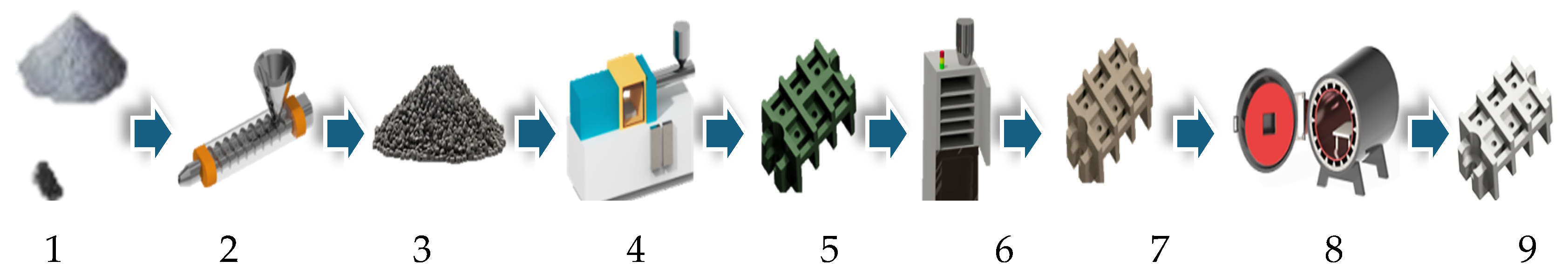
2.3. Production of the Test Specimen

During the tests, we used tensile test specimens specially designed by the Metal Powder Industries Federation (MPIF) for metal injection molding, which were easy to handle, measure and compare. The test specimens were carried out according to the technological process, i.e., injection molding, binder removal and sintering [10]. Injection molding was carried out on a Battenfeld BA 600 injection molding machine (WITTMANN BATTENFELD GmbH, Kottingbrunn, Austria), and the used parameters are shown at Table 2. In practice, recycling meant that after the production of the required number of samples for sampling (6 pieces), the remaining amount of material was injected and then shredded with a grinding device. After grinding, another injection molding cycle was performed by feeding the recycled material back into the machine. This process took place eight times in total, together with the first injection molding step.
Further technological steps were completed for half of the samples from different generations, while the other half remained “green”. Thus, 3 specimens from each cycle were analyzed, both in the finished metallic and semi-finished “green” conditions.

2.4. Test Methods

Evaluations were performed for the samples presented earlier in two separate states. In the first step, scanning electron micrographs were performed on the broken surface of the “green” products still containing the binder, for which we used a Zeiss Sigma 300VP-type electron microscope (Carl Zeiss AG, Oberkochen, Germany), where images of the binder and metal particles were taken with a BSD detector. XRD-based spectroscopy and an EDS sensor were used to prepare the elemental analysis. The embedded samples from the sintered specimens with already metallic properties and the tissue structure were examined using a Zeiss Axio Imager M2m type microscope. The surfaces of the samples were etched with 2% nital for 10–12 s. The completed recordings were evaluated using the ImageJ open-source software (Version 1.48q).

3. Results and Discussions
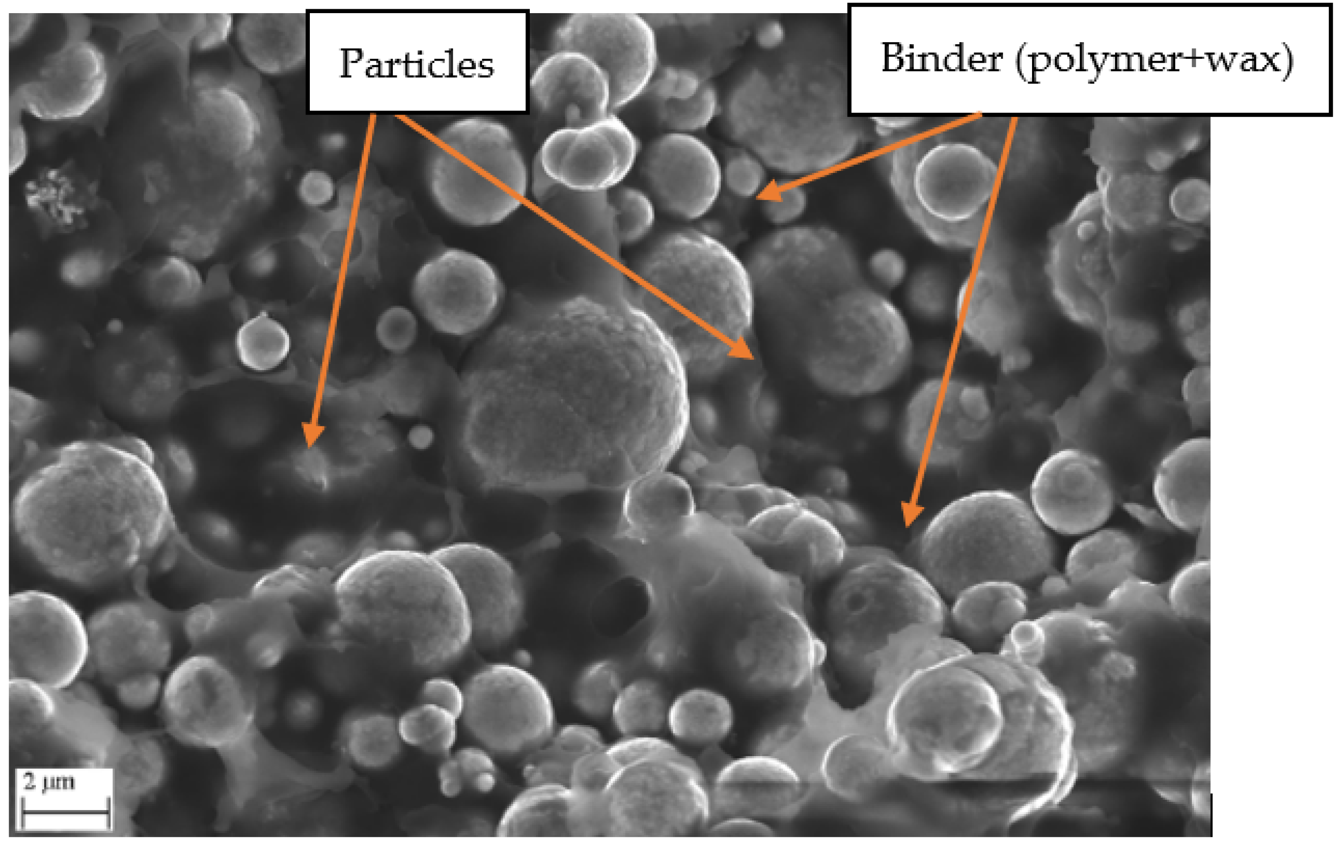
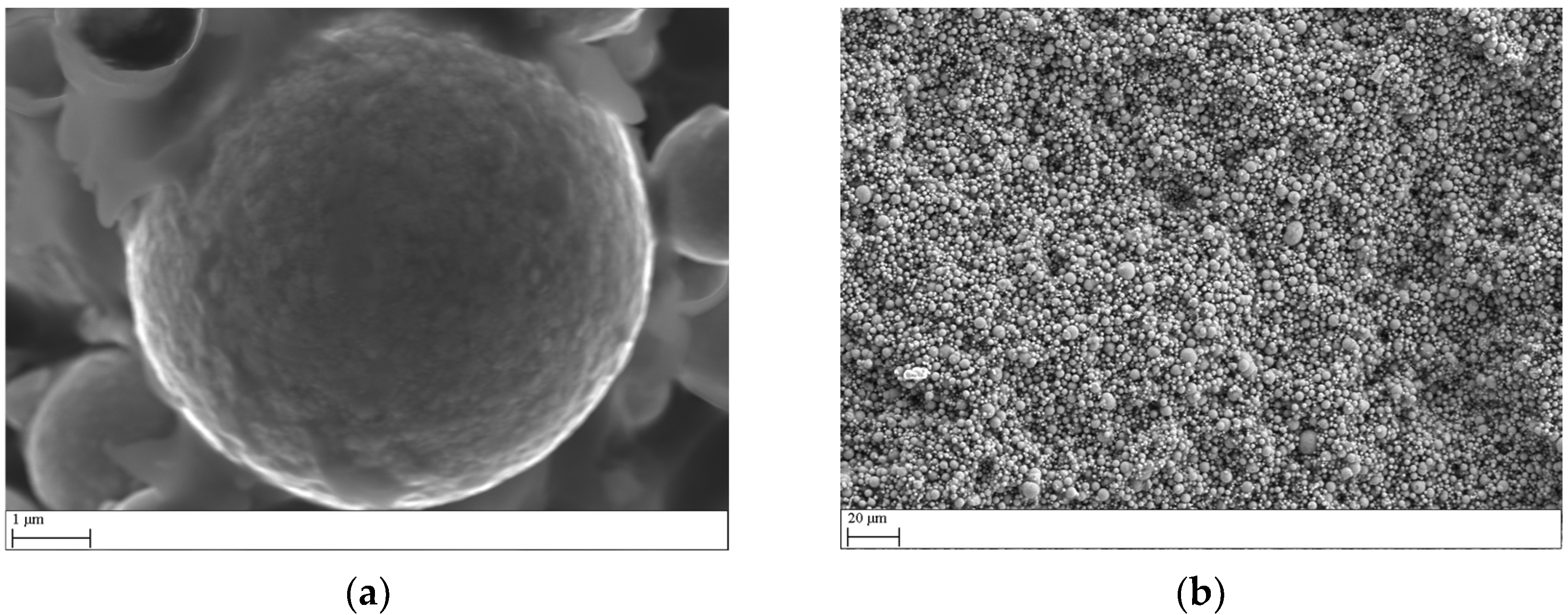
3.1. SEM Images

In order to make the injection molding materials more studiable and perceptible, the electron microscopic images taken of them are presented. Figure 2 shows the injection-molded product, which still contains a large amount of binder. It is important to mention that the recordings always come from the broken surface of the specimen.

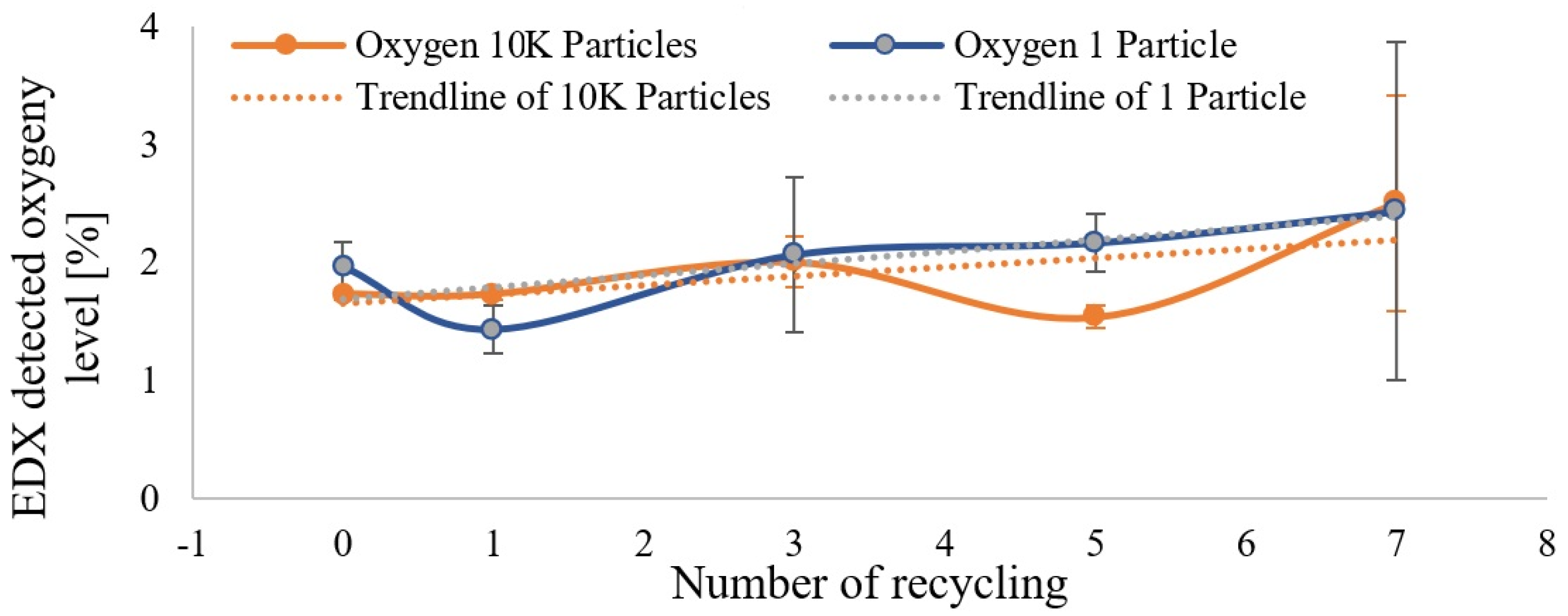
3.2. EDX-Based Spectroscopy

According to the literature research, the test was used to determine the amount of oxide on the fracture surface of the injection-molded product. The processing temperature of the melt took place at 220 °C, which to a small extent promoted the oxidation of the surface of the grains, since the alloy was not corrosion-resistant. The examination was carried out in two ways: first by scanning a larger area, where the results of approximately 10–15 thousand particles were detected, and then at a much higher magnification, where the surface of approximately one particle is evaluated. Based on the images taken with the SEM BSD Detector shown in Figure 3, the examined surface is clearly visible.
During the measurement, a question arose as to how to evaluate the distribution of percentages. The detector clearly detected all elements in the scanned area and gives its percentage. During the test, it occurred only sporadically in the mixture, an element that was not an essential constituent of any component. Therefore, the evaluation was always carried out for the same six elements, which were known to be the constituent elements of the components: C (Carbon), O (oxygen), Si (Silicon), Fe (Ferrite), Ni (Nickel), and Mo (Molybdenum).
The results from both the measurements involving many particles and those focusing on individual particles were consistent, showing similar increases in oxygen levels. Although the exact residence time was not measured, the observed increases in oxygen content supported the assumption that repeated reprocessing led to a longer residence time of the material in the chamber, which likely contributed to the growth of the oxide layer on the particle surfaces. Figure 4 presents the measurement results along with the corresponding standard deviations. The diagram shows that the oxygen content remained relatively stable as the number of generations increased, but it began to rise after the fifth generation. It also indicates that the oxygen content measured on larger particles provided more consistent results, with a smaller standard deviation.

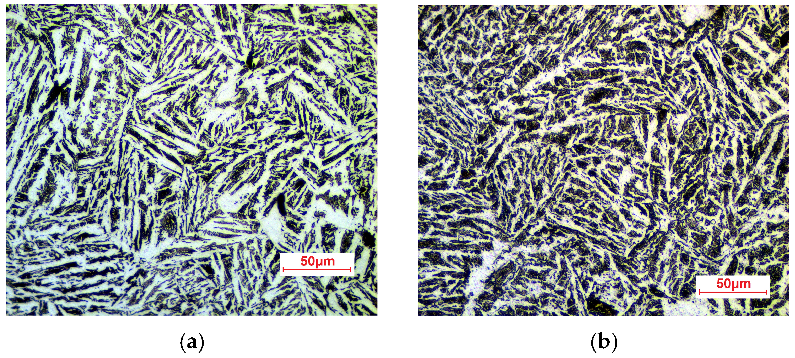
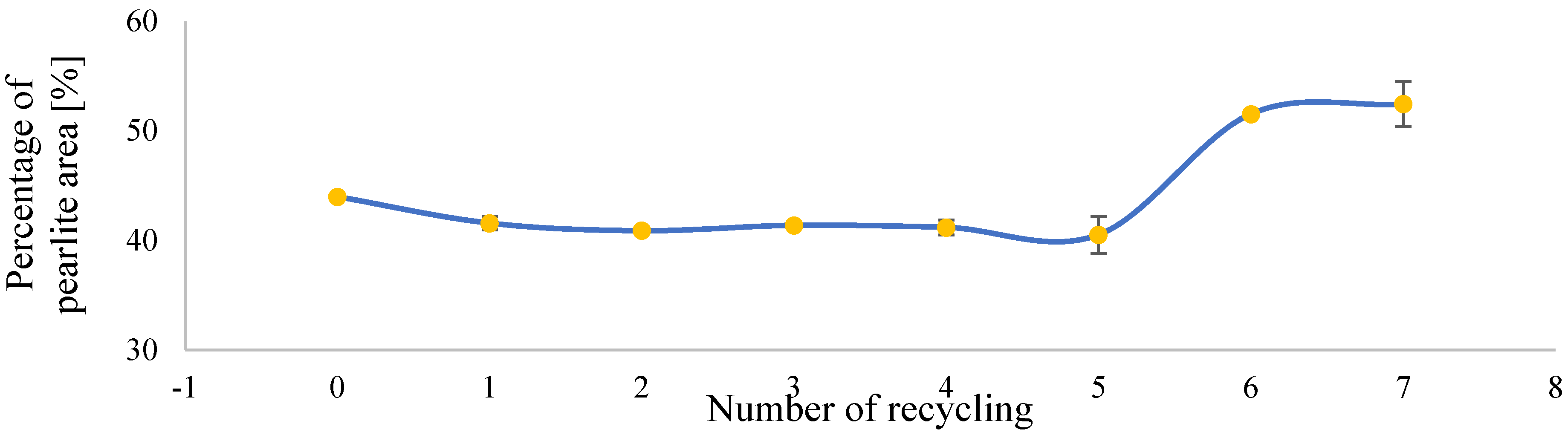
3.3. Metallographic Examination of Sintered Specimen

We took pictures of the fabric structure of the tensile test specimens after embedding in resin. It is clear from the recordings that the tissue structure consisted of a light single-phase field (ferrite) and a darker, presumably two-phase field (pearlite). The optical microscopic images for each generation were evaluated from recordings taken at two positions using image analysis software. According to the assumption described in the introduction, reprocessing worsened the ratio of the binder system, which greatly worsened further technological steps. During the removal of the thermal binder, due to the insufficiently porous structure, the polymer could not leave sufficiently, which, by diffusing into the metallic grid, increased its carbon content. This should appear in the structural images of the fabric as an increase in the proportion of pearlite, so image analysis was used to determine the proportion of pearlite. It is difficult to see the difference with the naked eye, so Figure 5 compares the two microstructures with significantly different ratios, which are position 1 (41.9% pearlite) of the fourth generation (a) and position 1 from the seventh generation (b) (54.48% pearlite).50µm
In order to ensure the accuracy of the evaluation, when selecting the positions, we tried to prepare a survey showing the characteristic features of the sample. All recordings were evaluated with the help of the image analysis software, which can be seen in the diagram in Figure 6.

4. Conclusions

The tests yielded many positive results. Based on the electron microscopic images and the related EDS detector analyses, it can be established that the oxygen content of the mixture increased by approximately 0.5% during reprocessing. This supports the hypothesis that the number of reprocessing steps negatively affected the initiation of material transport between particles. Furthermore, microstructure tests of the sintered specimens, with the help of image analysis software, showed that the increase in the number of reprocessing after the fifth generation resulted in a nearly 10% increase in the pearlite content of the alloy.

Author Contributions

Conceptualization, Z.W. and G.L.; methodology, G.L.; validation, S.M., Z.W. and G.L.; formal analysis, Z.W.; investigation, F.T and G.L.; writing—original draft preparation, G.L.; writing—review and editing, Z.W.; visualization, F.T.; supervision, Z.W. All authors have read and agreed to the published version of the manuscript.

Funding

This research was funded by the National Research Development and Innovation Office through the Thematic Excellence Programme 2021 (TKP2021)—National Defence of the National Security Subprogramme at the Szechenyi Istvan University (TKP2021-NVA-23).

Institutional Review Board Statement

Not applicable.

Informed Consent Statement

Not applicable.

Data Availability Statement

The raw data supporting the conclusions of this article will be made available by the authors upon request.

Acknowledgments

The experiments were supported by AFT Hungary Kft. Project no. TKP2021-NVA-23 has been implemented with the support provided by the Ministry of Technology and Industry of Hungary through the National Research, Development and Innovation Fund, financed under the TKP2021-NVA funding scheme. This work was supported by the Janos Bolyai Research Scholarship of the Hungarian Academy of Sciences (Z.W.).

Conflicts of Interest

The authors declare no conflicts of interest. AFT-Hungary Kft has no conflict of interests.

References

  1. Heaney, D.F. (Ed.) Handbook of Metal Injection Molding, 2nd ed.; Elsevier: Amsterdam, The Netherlands, 2019; Volume 636. [Google Scholar]
  2. Hauck, P.A. Powder injection molding: Current and long term outlook. Int. J. Powder Metall. 2000, 36, 29–30. [Google Scholar]
  3. Petzoldt, F.; Eifert, H.; wig, T.H.; Kramer, L.; Veltl, G.; Pest, A. Broadening the Scope of MIM. Mater. Manuf. Process. 1997, 12, 691–711. [Google Scholar] [CrossRef]
  4. Ma, H.; Li, S.; Jin, Z.; Tian, Y.; Ren, F.; Zhou, Z.; Xu, W. Effect of 17-4PH stainless steel powders interaction on feedstocks. Powder Technol. 2020, 372, 204–211. [Google Scholar] [CrossRef]
  5. Omar, M.A.; Zainon, N. Powder Characterization, Mixing Behaviour and Rheological Properties of Magnesium Powder Feedstock for Metal Injection Moulding Process. Saudi J. Eng. Technol. 2020, 5, 509–514. [Google Scholar] [CrossRef]
  6. Bata, A.; Nagy, D.; Weltsch, Z. Effect of Recycling on the Mechanical, Thermal and Rheological Properties of Polypropylene/Carbon Nanotube Composites. Polymers 2022, 14, 5257. [Google Scholar] [CrossRef] [PubMed]
  7. Cheng, L.H.; Hwang, K.S.; Fan, Y.L. Molding Properties and Causes of Deterioration of Recycled Powder Injection Molding Feedstock. Metall. Mater. Trans. A 2009, 40, 3210–3216. [Google Scholar] [CrossRef]
  8. MatWeb Material Property Data. 4605 Low Alloy Steel [Internet]. Available online: https://www.matweb.com/search/datasheet.aspx?matguid=7f547e7b655f4e48a75409740309cb5a&ckck=1 (accessed on 18 March 2024).
  9. Optimim. [Internet]. Available online: https://optimim.com/en/metal-injection-molding-mim/material-options/low-alloy-steel/mim-4605-quenched-tempered-high-hardness (accessed on 13 May 2024).
  10. Narasimhan, K.S. Sintering of powder mixtures and the growth of ferrous powder metallurgy. Mater. Chem. Phys. 2001, 67, 56–65. [Google Scholar] [CrossRef]
Figure 1. Metal injection molding flow chart.
Engproc 79 00009 g001
Figure 2. SEM images of the “green” state.
Engproc 79 00009 g002
Figure 3. Electron micrographs of the measured surfaces: (a) single-particle-focused measurement; (b) measurement focused on a large number of particles.
Engproc 79 00009 g003
Figure 4. The oxygen content of the scanned surface layer.
Engproc 79 00009 g004
Figure 5. Images taken under an optical microscope at 500× magnification, etched with 2% natal. The fourth generation (a) and the seventh generation (b)
Engproc 79 00009 g005
Figure 6. Pearlite fabric element share in the analyzed cross-section.
Engproc 79 00009 g006
Table 1. Chemical composition of metal alloy expressed in w%/w% [8].
%FeCNiMoSi
Min.remain0.41.50.2-
Max.remain0.62.50.51.0
Table 2. The main technological parameters of the molding.
Set ParameterValue
Injection volume7.9–8.1 cm3
Injection pressure1900–2100 bar
Holding time3–5 s
Holding pressure980–1070 bar
Cooling time13 s
Mold temperature50 °C
Melt temperature190 °C
Cycle time30 s
Total number of specimens produced287 pieces
Total production time11 h
Disclaimer/Publisher’s Note: The statements, opinions and data contained in all publications are solely those of the individual author(s) and contributor(s) and not of MDPI and/or the editor(s). MDPI and/or the editor(s) disclaim responsibility for any injury to people or property resulting from any ideas, methods, instructions or products referred to in the content.

