Proceeding Paper

The Development and Evaluation of a High-Frequency Toroidal Transformer for Solid-State Transformer Applications †

Department of Electrical Engineering, College of EME, National University of Science and Technology, Islamabad 4600, Pakistan
*
Author to whom correspondence should be addressed.
Presented at the Third International Conference on Advances in Mechanical Engineering 2023 (ICAME-23), Islamabad, Pakistan, 24 August 2023.
Eng. Proc. 2023, 45(1), 11; https://doi.org/10.3390/engproc2023045011
Published: 8 September 2023

Abstract

:
The performance and efficiency of high-frequency transformers (HFTs) are significantly influenced by leakage inductance. To improve the efficiency of HFTs, it is crucial to consider the effects of leakage inductance during the design and analysis processes. This research study aims to investigate a high-frequency toroidal transformer by examining different magnetic materials (Ferrite, Amorphas, and Iron-Powdered Alloy), winding configurations (solid, twisted, and LITZ wire), and operating frequencies (10 kHz and 50 kHz). To validate the effectiveness of parametric optimization in enhancing the system efficiency, the designed toroidal HFT was constructed and tested in a 600/300 V 3 kW dual active bridge (DAB) converter. The leakage inductances were measured using a frequency sweeping LCR meter.

1. Introduction

Electromagnetics play a crucial role in various applications, particularly in transformer-based power electronics equipment. Parameters such as parasitic capacitance and leakage inductance significantly affect the efficiency and performance of these devices. Power electronics often utilize galvanic isolation-based topologies due to their compactness, active/reactive power flow management, and protection features. However, if a transformer has improperly linked primary and secondary windings, it experiences increased power losses and current and voltage spikes, leading to a lower efficiency. Therefore, it is important to consider the leakage inductance and parasitic components when developing efficient high-frequency transformers. In fact, incorporating leakage inductance and parasitic capacitance into a transformer can help in building LC tank circuits, resulting in a 15% decrease in the volume of soft-switching converters [1]. When working with higher frequencies, passive components can be made smaller at the cost of higher parasitic effects, which may experience current spikes [2]. To address these issues, various core materials can be employed. Ferrites are durable ceramics based on metal oxides that exhibit fewer core losses at a low cost [3]. However, ferrites have limitations such as a low tensile strength and significant permeability roll-off. Another category of core material are powdered magnetic cores, which are composed of alloyed powdered cores, soft magnetic powder composites, and powdered iron. Alloy powdered cores such as Moly-permalloy (MPP), High-flux, Kool Mµ, and XFlux offer stability at higher temperatures, a reduced leakage flux, low magnetostriction, and lower prices [4]. Powdered iron cores are the least expensive, but can be sensitive to temperature increases. Amorphous alloy cores are more robust and corrosion-resistant, making them suitable for medium-frequency transformers with temperature-dependent saturation flux density concerns [5]. In transformers, the leakage inductance energy is divided into two parts, one stored in the winding and the other in the insulation zone. Analytical techniques often ignore leakage inductance at high frequencies due to the magnetic field unevenness caused by eddy and proximity effects [6].
In this research article, various core materials (ferrite, iron-powdered alloy, and amorphas,) wire structures (round, twisted, and LITZ wire), and winding arrangements (single or multi-layer) are analyzed for the optimization of the leakage inductance behavior of different transformers.

2. Design and Analysis Procedure

The dual active bridge converter is composed of two full-bridge inverters that are linked through a high-frequency transformer. V p and V s are the primary and secondary square-wave voltage amplitudes, f s w is the switching frequency, and D is the duty cycle. Square-wave voltages generated by full bridges are used to calculate the leakage inductance L leak   , which is most appropriate variable for maximizing the power transfer abilities of DAB.
P p s = n V p V s D ( 1 D ) 2 π f s w L leak  
The transformer is designed using the geometrical constant of the core, which can be seen from Table 1. The leakage inductance of a transformer is adjusted by experimenting with the value of the mutual inductance. The number of turns and geometrical arrangement of the core of a transformer are the few key parameters for determining the leakage inductances. The below section provides a collection of the essential formulae used to select an appropriate core material. The effective area and effective length of the toroidal core are calculated using Equations (2) and (3), while the energy stored in the core and volume from Equations (4) and (5).
A core = h O D I D 2
l core = π O D + I D 2
E store = A core l core B m a x 2 2 μ
V core = 2 E store μ B m a x 2
The magnetic core volume is proportional to the permeability μ of the core material and inversely proportional to the square of B m a x , as described in Equation (5). Thus, magnetic materials with a greater saturation flux density B sat   are appropriate for small-volume transformers. The B m a x and μ values were taken from the material data sheet. Three HFTs are simulated in ANSYS using three cores of different materials wound with three wire arrangements such as round, twisted, and LITZ wire. Excitation is assigned by sectioning the copper coil and specifying turns. The leakage inductance and parasitic capacitance are calculated using the eddy current and magnetostatic solvers. The HFT used in dual active bridge converters is shown in Figure 1a, and the leakage inductance measurement setup in Figure 1b.
Leakage Inductance Calculations: The leakage inductance levels in a transformer are influenced by the material and core structure. In this study, ANSYS Maxwell was used to calculate the leakage and magnetizing inductance for different core materials. To facilitate an easy comparison of the leakage and parasitic qualities, the magnetizing inductance of the transformer designs was deliberately kept similar during the simulations. Based on the simulation analysis, the Ferrite core wound with a twisted wire construction exhibited the best results as tabulated in Table 2. Consequently, a hardware prototype was built using a ferrite core wound with isolated twisted wire to validate the results. Table 3 demonstrates that the hardware results for the leakage inductance and parasitic capacitance closely match the simulation results.

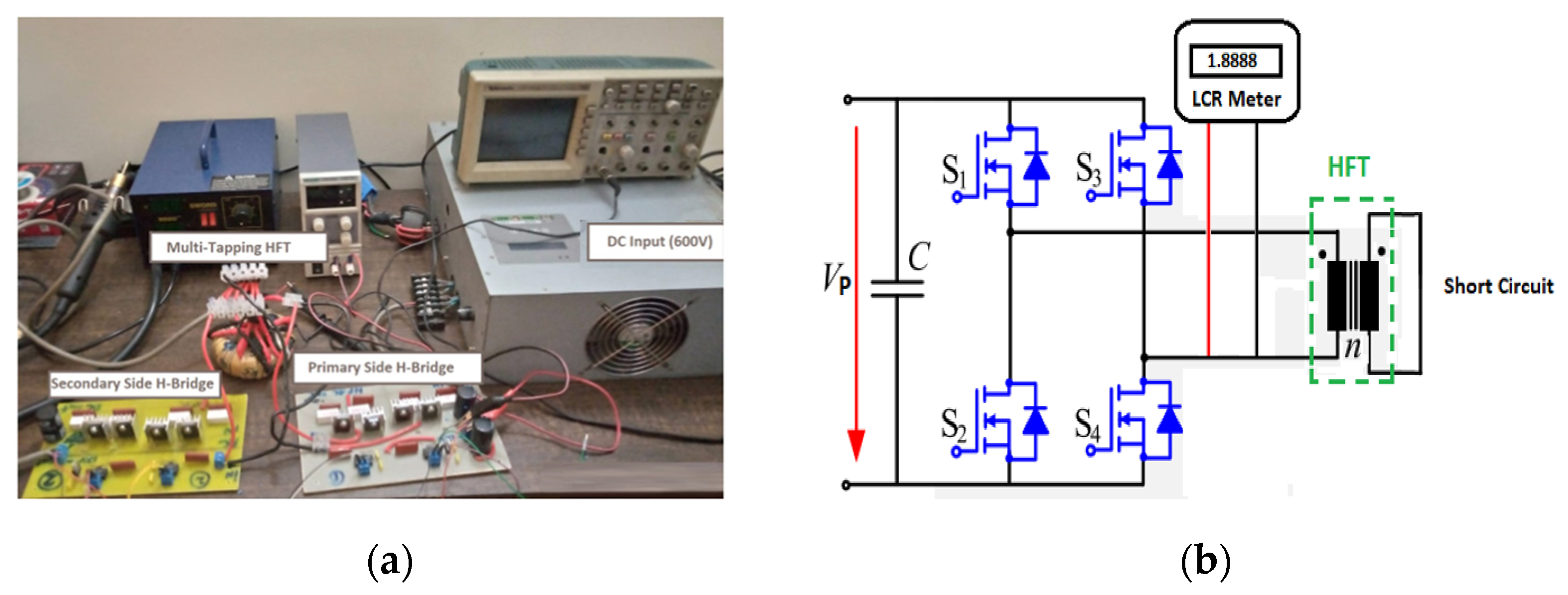
3. Results and Discussion

The simulation of a high-frequency transformer was conducted using ferrite, microlite, and MPP cores, wound with solid round wire, twisted wire (isolated strands), and LITZ wire. Power electronics magnetics (PEmag TM) in ANSYS calculated the leakage inductance through a finite element analysis (FEA). To validate the results, a hardware prototype was fabricated using a ferrite core wound with a twisted pair (isolated strands).
Table 3 presents a comparison between the simulation and experimental results, noting that the leakage inductance values apply to both the primary and secondary windings. The prototype transformer was measured for three scenarios using a BK Precision 880 LCR meter. The minimal difference between the simulation and experimental results was attributed to the careful implementation of the hardware prototype. The high-frequency transformer design demonstrated positive characteristics for leakage inductance at 10–50 kHz switching frequencies. This eliminated the need for a large series inductor to optimize the power transfer for a DAB converter.

4. Conclusions

Achieving a balance between leakage inductances is a challenging task that heavily relies on design parameters. Adjusting the core size, material, or number of turns alone is not enough to effectively reduce leakage inductance. A Finite Element Analysis (FEA) provides more accurate results compared to traditional analytical methods when computing these values. Simulations on various test cases helped us to determine the optimal parameters. A high-frequency transformer prototype was then implemented for validation. At an operating frequency of 50 kHz, optimal values for leakage inductance were achieved in a ferrite core wound with twisted wire.

Author Contributions

Conceptualization, A.S. and T.I.; methodology, A.S. and T.I.; software, A.S.; validation, A.S.; formal analysis, A.S. and T.I.; investigation, A.S.; data curation, A.S.; writing—original draft preparation, A.S.; writing—review and editing, A.S.; supervision, T.I. and A.U.H.; project administration, A.U.H. All authors have read and agreed to the published version of the manuscript.

Funding

This research received no external funding.

Institutional Review Board Statement

Not applicable.

Informed Consent Statement

Not applicable.

Data Availability Statement

Not applicable.

Conflicts of Interest

The authors declare no conflict of interest.

References

  1. Amini, M.; Almassalkhi, M. Trading off robustness and performance in receding horizon control with uncertain energy resources. In Proceedings of the 2018 Power Systems Computation Conference (PSCC), Dublin, Ireland, 11–15 June 2018; pp. 1–7. [Google Scholar]
  2. Saadatmand, S.; Shamsi, P. Adaptive critic design-based reinforcement learning approach in controlling virtual inertia-based grid-connected inverters. Int. J. Electr. Power Energy Syst. 2021, 127, 106657. [Google Scholar] [CrossRef]
  3. Rhaman, M.; Matin, M.; Hossain, M. Ferromagnetic, electric, and ferroelectric properties of samarium and cobalt co-doped bismuth ferrite nanoparticles. J. Phys. Chem. Solids 2020, 147, 109607. [Google Scholar] [CrossRef]
  4. Imaoka, J.; Okamoto, K.; Shoyama, M. Modeling, magnetic design, simulation methods, and experimental evaluation of various powder cores used in power converters considering their dc superimposition characteristics. IEEE Trans. Power Electron. 2019, 34, 9033–9051. [Google Scholar] [CrossRef]
  5. Ahmed, S.; Chang, K.-C.; Nguyen, T.-T.; Chu, K.-C.; Chang, F.-H.; Wang, H.-C. Interleaved DC/DC Boost Converter for Hybrid Electric and Electrical Vehicles; Springer: Cham, Switzerland, 2021; pp. 708–716. [Google Scholar]
  6. Nan, X.; Sullivan, C.R. An equivalent complex permeability model for Litz-wire windings. IEEE Trans. Ind. Appl. 2009, 45, 854–860. [Google Scholar] [CrossRef]
Figure 1. (a) Hardware setup of dual active bridge and (b) leakage inductance measurement.
Engproc 45 00011 g001
Table 1. HFT design specifications.
Test CasesCase 1Case 2Case 3
Core MaterialFerriteIron-Powdered Alloy (MPP)Amorphas (Microlite)
Optimal Flux Density (Tesla)0.250.90.7
Dimension (OD, ID, H) 85 , 53 , 20   m m 85 , 53 , 20   m m 85 , 53 , 20   m m
Number of Turns (Primary, Secondary)100, 50100, 50100, 50
Wire Gauge (Primary, Secondary)21, 2121, 2121, 21
Numbers of Strands (Primary, Secondary)5, 35, 35, 3
Voltage (Primary, Secondary)600, 300600, 300600, 300
Frequency (kHz)101010
Table 2. HFT Simulations of different core materials and wire structures at 10 kHz frequency (Np = 100, Ns = 50).
Windings ConfigurationCore MaterialMagnetizing Inductance ( m H ) Leakage Inductance ( μ H )
Primary SecondaryPrimarySecondary
WindingWindingWindingWinding
Round WireFerrite47.311.589.0024.20
Microlite34.78.32191.2127.7
MPP33.18.91191.1126.4
Twisted Wire (isolated strands)Ferrite46.111.169.0014.00
Microlite35.38.31189.2119.7
MPP34.79.12191.1120.4
LITZ wireFerrite47.910.961.0012.10
Microlite34.98.12181.2117.1
MPP34.89.01181.9117.9
Table 3. Comparison of simulation and experimental results for twisted wire (isolated strands) wound HFT.
ParametersUnit10 kHz50 kHz
SimulationExperimentalSimulationExperimental
Inductance (Primary) m H 46.146.540.542.9
Inductance (Secondary) m H 11.111.39.709.95
Leakage Inductance (Primary) μ H 69.070.21.01.18
Leakage Inductance (Secondary) μ H 14.114.84.004.73
Disclaimer/Publisher’s Note: The statements, opinions and data contained in all publications are solely those of the individual author(s) and contributor(s) and not of MDPI and/or the editor(s). MDPI and/or the editor(s) disclaim responsibility for any injury to people or property resulting from any ideas, methods, instructions or products referred to in the content.

