1. Introduction
The advent of advanced imaging modalities has had a great impact and provided advantages in diagnosis and treatment planning in the head and neck region. Being the most complex region, two-dimensional imaging can be used as a preliminary diagnostic order, but complex diagnosis and treatment planning requires advanced imaging.
In the various imaging modalities of the head and neck, we can divide them into those indicated for (i) odontogenic pathology/hard tissue imaging (predominantly cone beam computed tomography) and (ii) non–odontogenic/trauma and malignancy (computed tomography, magnetic resonance imaging, contrast imaging, and PET scans).
There has been an innumerable amount of studies and reviews on the advantages of imaging modalities in the head and neck region. This review is intended to explore the other side—the few disadvantages and diagnostic inhibitions. This paper attempts to bring up solutions and rectifications that can significantly increase the quality of imaging.
2. Cone Beam Computed Tomography
2.1. Imaging Pitfalls
Even though CBCT is used in the case of effective imaging and treatment planning for dental implants, maxillofacial trauma, and assessment of odontogenic pathologies, random artifacts greatly decrease the diagnostic ability. There are many different types of CT artifacts, including noise, beam hardening, scatter, pseudo enhancement, motion, cone beam, helical, ring, and metal artifacts. Manufacturers minimize beam hardening by using filtration, calibration correction, and beam hardening correction software [
1,
2].
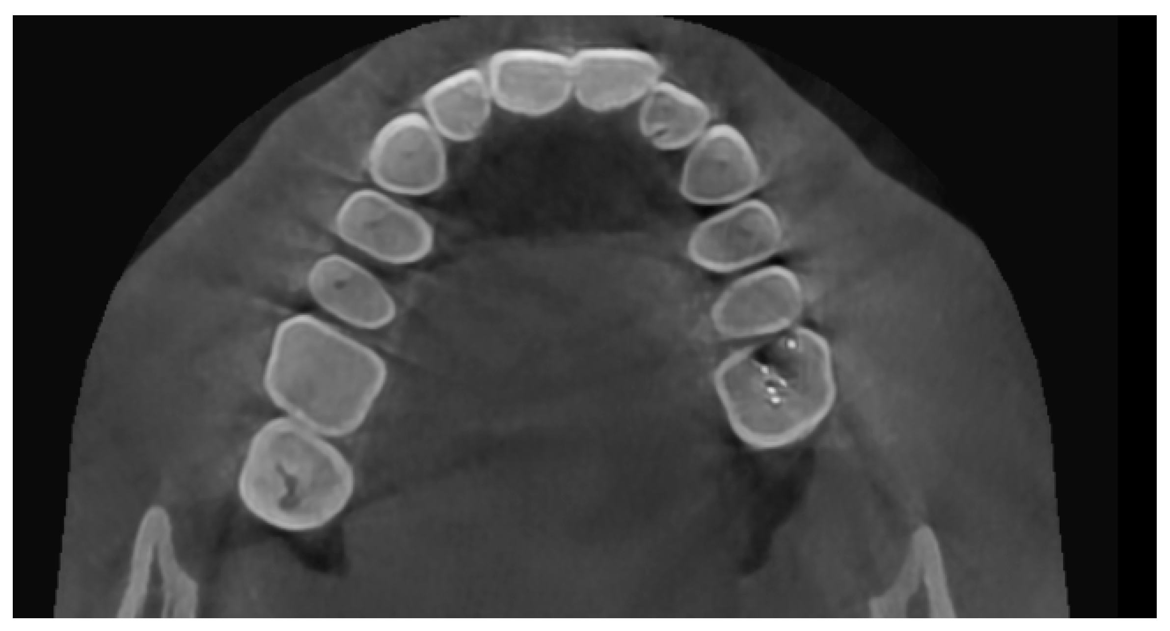
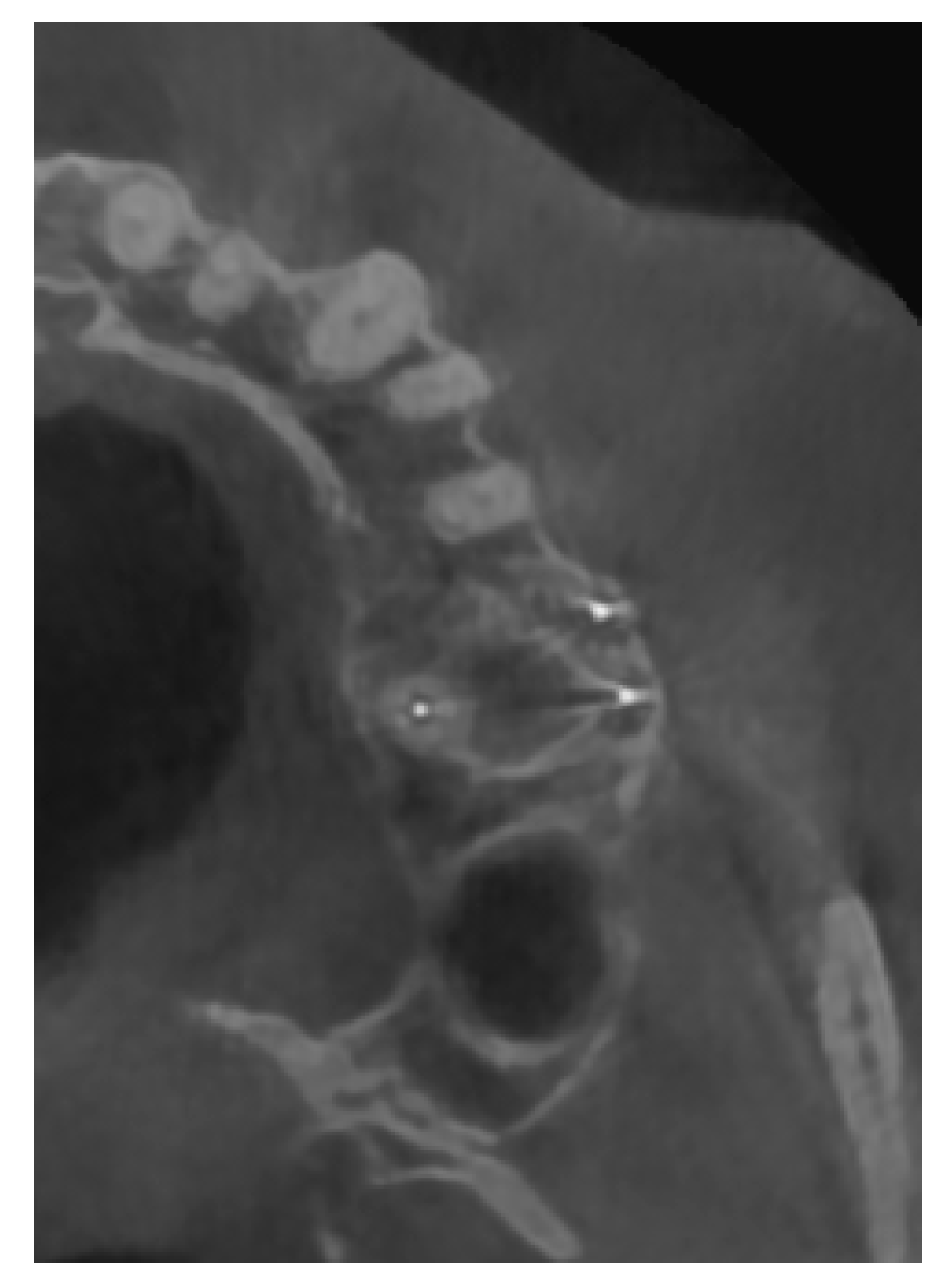
Consider a case in which the patient presented with chronic left-sided sinusitis. There was a root canal-treated tooth in relation to the left maxillary molar. No clinical signs were evident with regard to teeth. On an intraoral periapical radiograph, obturation seemed to be normal, but revealed well-defined periapical pathology. The extent of the pathology was not assessable, and the periapical pathology was suspected to be the source of the sinusitis infection.
On CBCT, there were beam hardening streaking artifacts (black lines) present in the volume (
Figure 1). Upon assessing the axial section at the root end–maxillary sinus floor interface, the streaking artifact had mimicked the destruction of the sinus floor and communication between the sinus and periapical pathology (
Figure 2), indicating a radiodiagnosis of odontogenic sinusitis. Upon a surgical exploration with root end surgery, this was proven to be a periapical scar and an intact maxillary sinus floor.
The artifacts in CBCT are similar to those in CT, but they are more pronounced in CBCT due to the heterochromatic X-ray beam present in CBCT and the lower mean kilovolt (peak) energy compared with conventional CT.
2.2. Diagnostic Inhibitions
CBCT has very low soft tissue resolution. It is still used for odontogenic/nonodontogenic cysts of the jaws and trauma of the head and neck.
CBCT does not give us differential density values for soft tissues and fluid. The Hounsfield unit and CBCT gray values are highly correlated, which has been proven in multiple research studies [
3,
4]. Recent studies have attempted to diagnose cysts and soft tissue pathologies through CBCT gray scale values. In a study by Meryem Etöz et al. [
5] identifying radicular cysts or apical granulomas using CBCT, a seven-criteria method was used. The criteria included the relationship of lesions with dental roots, periphery of the lesion, shape, darker focus in the center, root resorption, displacement in related teeth, and cortical bone perforation. In addition, the minimum and maximum gray scale values of the lesions were measured and compared. It was concluded that there was no relationship between the histopathological diagnosis of lesions and CBCT gray scale values [
5].
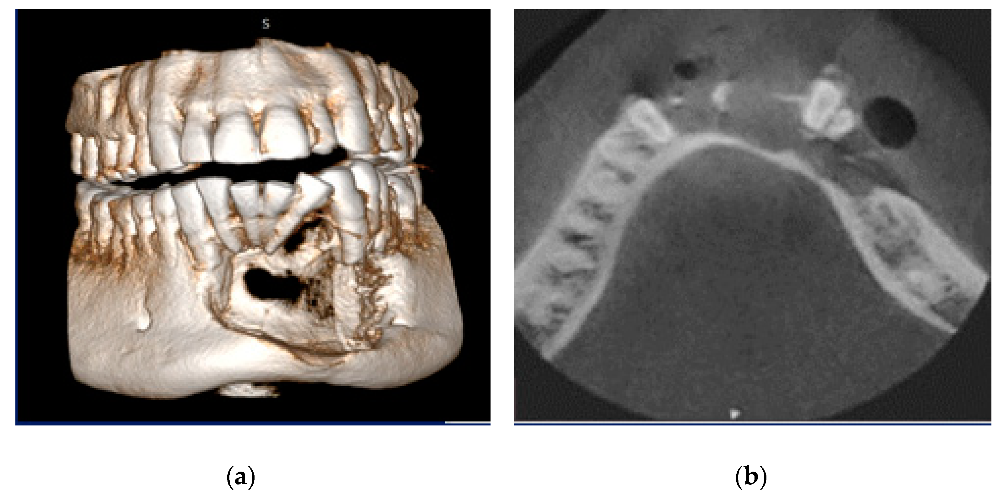
This concept can be explained by a case of swelling in the lower jaw for the past 9 months. No associated pain, numbness, or paresthesia were present. Clinically, distal tipping of 32 and mesial tipping of 33 were evident. Upon vitality testing, 42, 41, 31, and 32 were found to be nonvital. A clinical provisional diagnosis of the radicular cyst was given. The aspiration of the lesion revealed a straw-colored fluid. On CBCT, the pathology in the anterior mandible was evident, with buccal cortical bone destruction, and the internal structure revealed thin septa not extending throughout the lesion (
Figure 3a,b). This posed a diagnostic dilemma of either a tumor or a cystic lesion. The gray scale value did not provide insight into the internal structure. The histopathological diagnosis was plexiform ameloblastoma, an odontogenic tumor with centric cystic degeneration.
3. Computed Tomography (CT)
Computed tomography has been widely indicated in head and neck trauma, pan-facial trauma, and suspected head injuries. CT has been indicated in cases of soft tissue involvement (orbital trauma), pan-facial trauma hindering soft tissue, muscular function, and enophthalmos.
Due to the lack of immobilization of an acute trauma patient, artifacts may be more frequent and nerve canal involvement/muscle involvement may not be assessed.
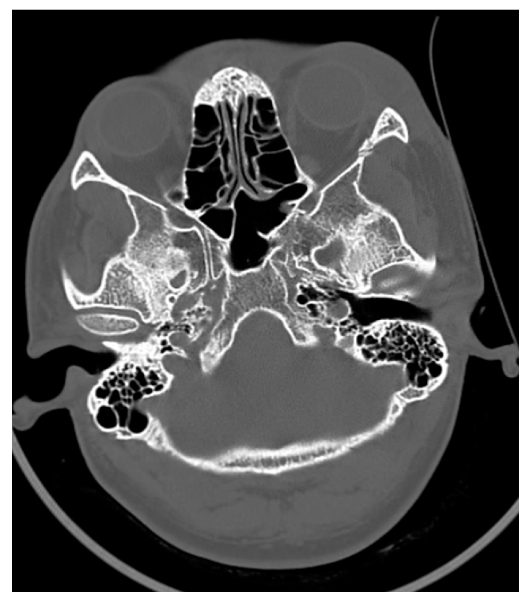
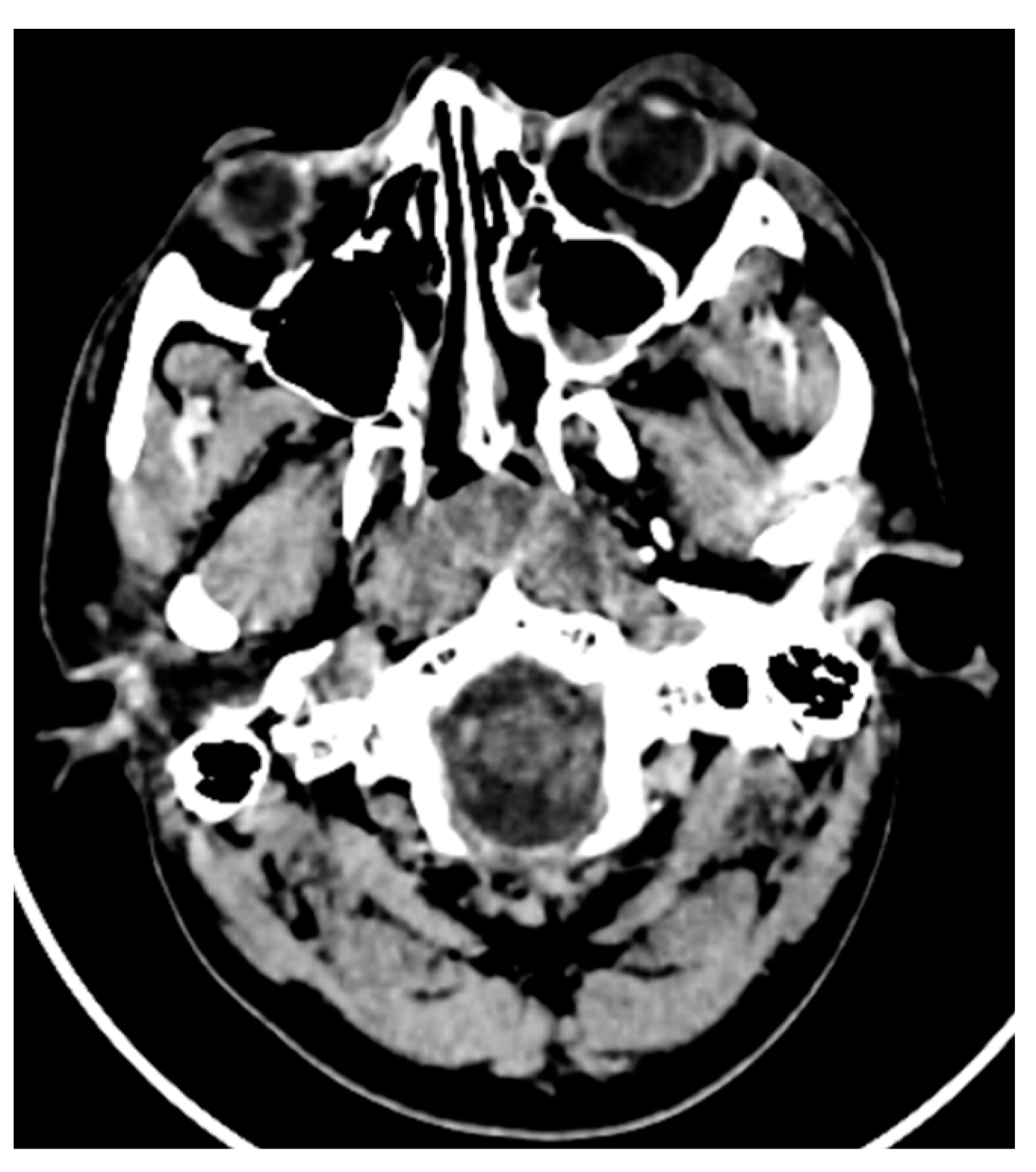
In a case of zygomatic complex fracture, orbital involvement revealed a linear minimally displaced fracture noted involving the left zygomatic arch, the lateral wall of the left orbit. A comminuted displaced fracture involving the lateral wall of the left maxillary sinus with fracture fragments lying inside was associated with hemosinus (
Figure 4 and
Figure 5). However, the soft tissue window failed to reveal further details with regard to the pterygoid muscles and orbital volume. Other than the displacement and type of fractures, the extent of orbital involvement also determines surgical treatment in this case. The most common cause of posttraumatic enophthalmos is increased orbital volume [
6]. All images were taken using 5th generation mono-energy CT machines with standard exposure parameters of 140 kvp, 200 mA soft tissue with a slice thickness of 0.5–0.6 mm, and bony windows.
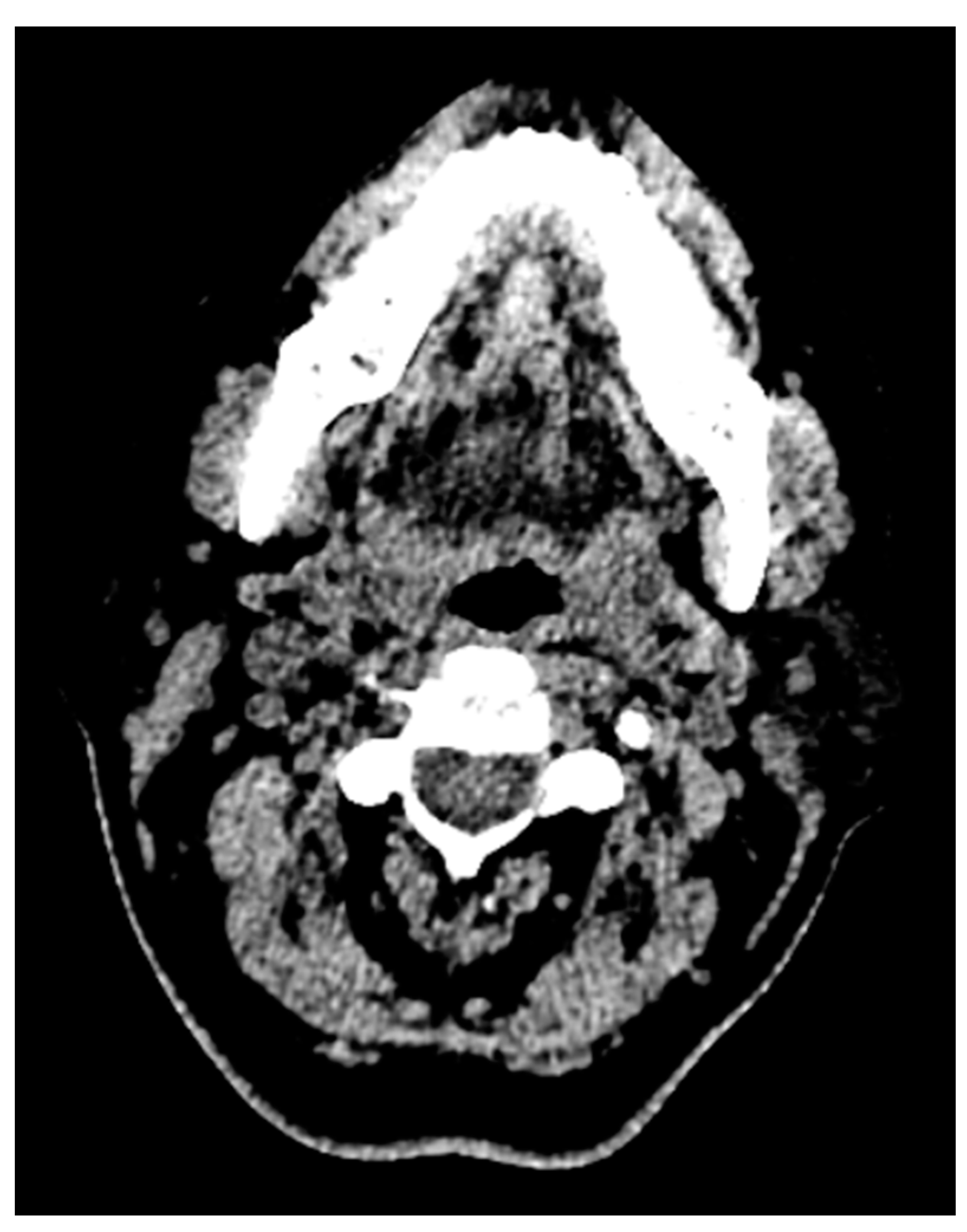
One more case of a photon starvation artifact hindering the assessment of the tongue pathology and its extent in a computed tomography image is presented in
Figure 6.
This photon starvation, or quantum mottle, greatly hindered the diagnostic quality of the image. This results from insufficient X-ray photons reaching the sensor from the patient. Even though techniques such as tube current modulation (TCM) and vendor-specific and iterative reconstruction algorithms can reduce this effect, these types of artifacts still represent considerable hindrances to diagnosis and assessment.
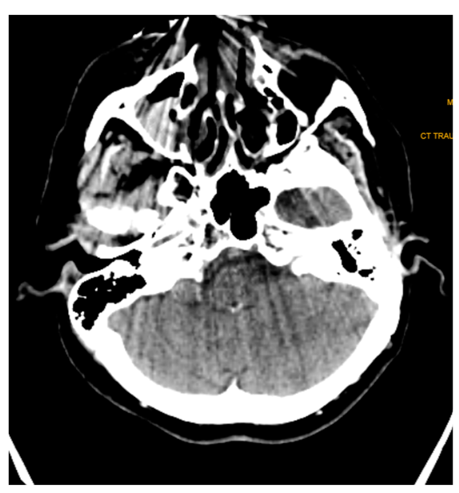
Streak and windmill artifacts greatly affect the scan images in CT. Windmill artifacts occur due to under-sampling along the Z axis, which usually occurs in the clavicle region and the base of the skull region, where drastic anatomical changes and differential Hounsfield units are present. A black streak artifact of the beam hardening effect greatly disrupting the diagnostic quality can be seen in
Figure 7.
4. Magnetic Resonance Imaging (MRI)
Magnetic resonance imaging is used in head and neck imaging predominantly for ruling out craniofacial neuralgias, soft tissue extension of pathologies and malignancies of the head and neck, diagnosis, and treatment planning.
The most common artifact present in MRI is motion blurriness (due to long scan time) and metal artifacts.
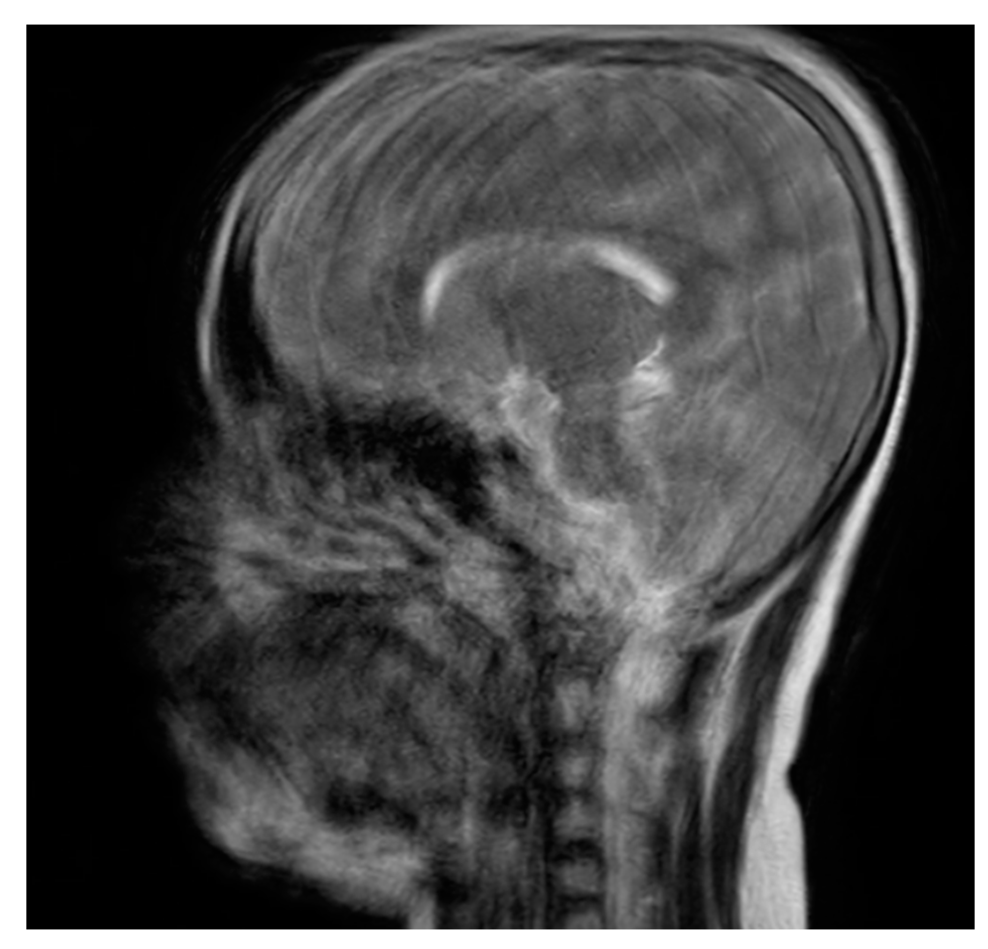
Motion blurriness happens due to patient motion, swallowing, and even breathing in the case of the head and neck region. The degree of blurriness could fall into a range of minimal to extensive blur. A pediatric MRI image with severe motion blurs and distortion of the image is presented in the sagittal section (
Figure 8). This kind of artifact requires a re-scan.
Metal artifacts manifest in multiple forms—a complete signal loss may be observed around the metallic object, or a rim of high signal intensity may be present around the metallic devices. Metal-induced artifacts are still a challenging aspect of imaging. Many technical methods and minor alterations have been proposed to reduce the presence of metal-induced artifacts in MRI, such as view-angle tilting method, MAVRIC (multi-acquisition variable resonance image combination), and SEMAC (slice-encoding for metal artifact correction) can be used in the plane and through-slice displacements, but at a cost of increased scan time, further increasing the inconvenience [
7,
8,
9].
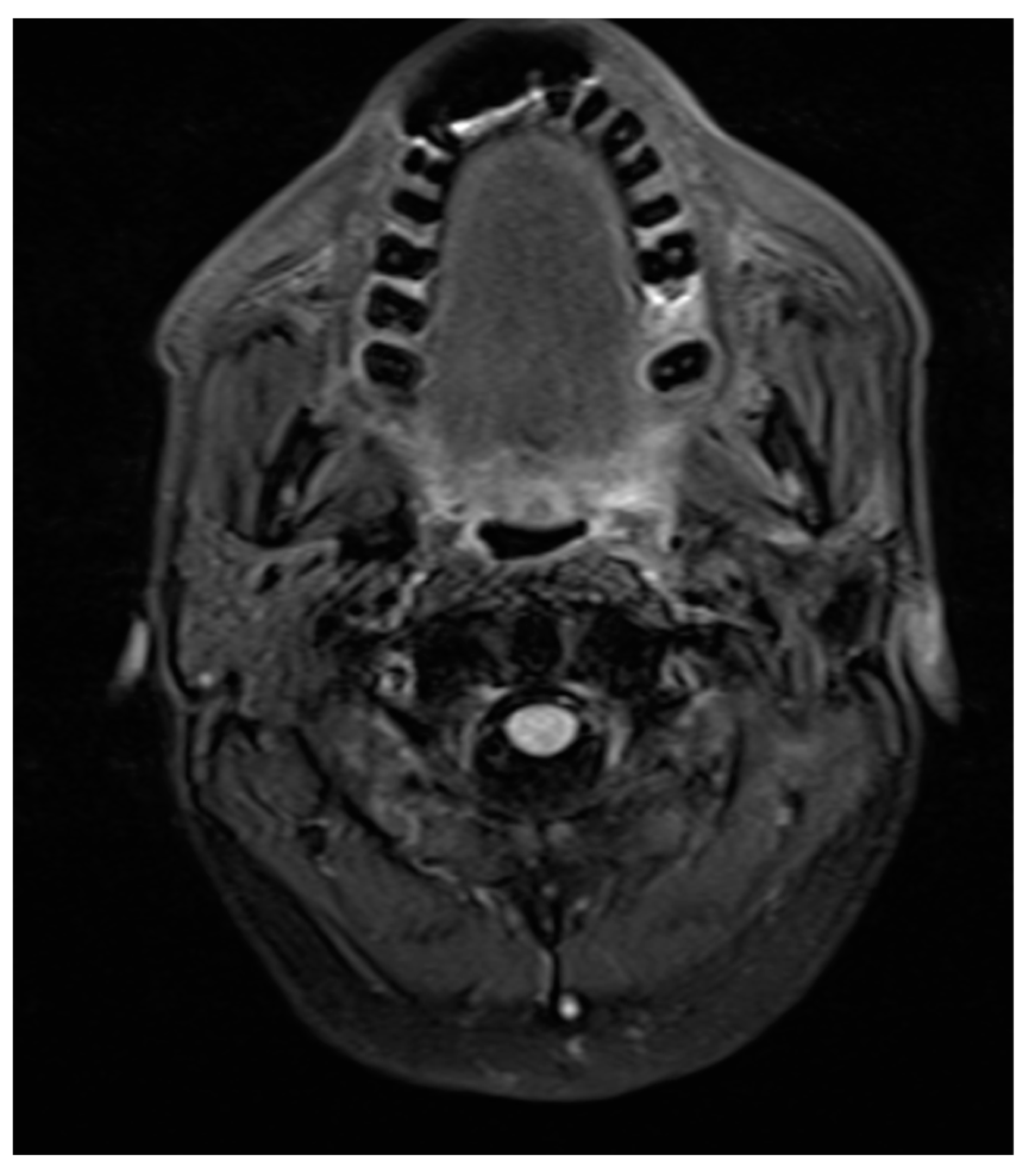
A similar example is presented in the T2 axial section (
Figure 9). The porcelain fused to metal fixed prosthesis placed in the mandibular anterior teeth caused a no-signal, presenting anterior artifact extending to the level of the maxillary teeth. This is a particularly inconvenient problem since the MRI imaging was performed to check for any malignant spread in a recurring cancer patient. Although different technical alterations gave us a clue about the region in one plane, it was not sufficient.
Positron Emission Tomography
PET-CT (Positron Emission Tomography—Computed Tomography) is used to identify, locate, and assess the anatomy and function of hypermetabolic tissue. It uses 18-FDG (fluorodeoxyglucose) as a medium. The signals are then read by the system. 18-FDG PET-CT is one of the most accurate methods for diagnosing primary HNC lesions. The lesion cannot be accessed via visual inspection, with or without concurrent vision-guided biopsy [
10]. The specificity of PET-CT for identifying inspection-occult oropharyngeal SCC has been measured at over 90%. According to the NCCN (National Comprehensive Cancer Network), PET-CT is indicated for initial diagnosis for the following types of physical examination for occult HNC (Head and Neck Cancers): oral cavity, supraglottic larynx, ethmoid sinus, glottic larynx, oropharynx, and maxillary sinus [
11,
12].
It is widely used as a recall–review imaging modality for post-treatment follow-up cases. The false positive possibility of PET-CT poses a major diagnostic inhibition and a major pitfall. This is the reason why PET-CT has been avoided for post-radiation and therapy patients for at least up to 8–12 weeks (to avoid post-inflammatory effects) [
13].
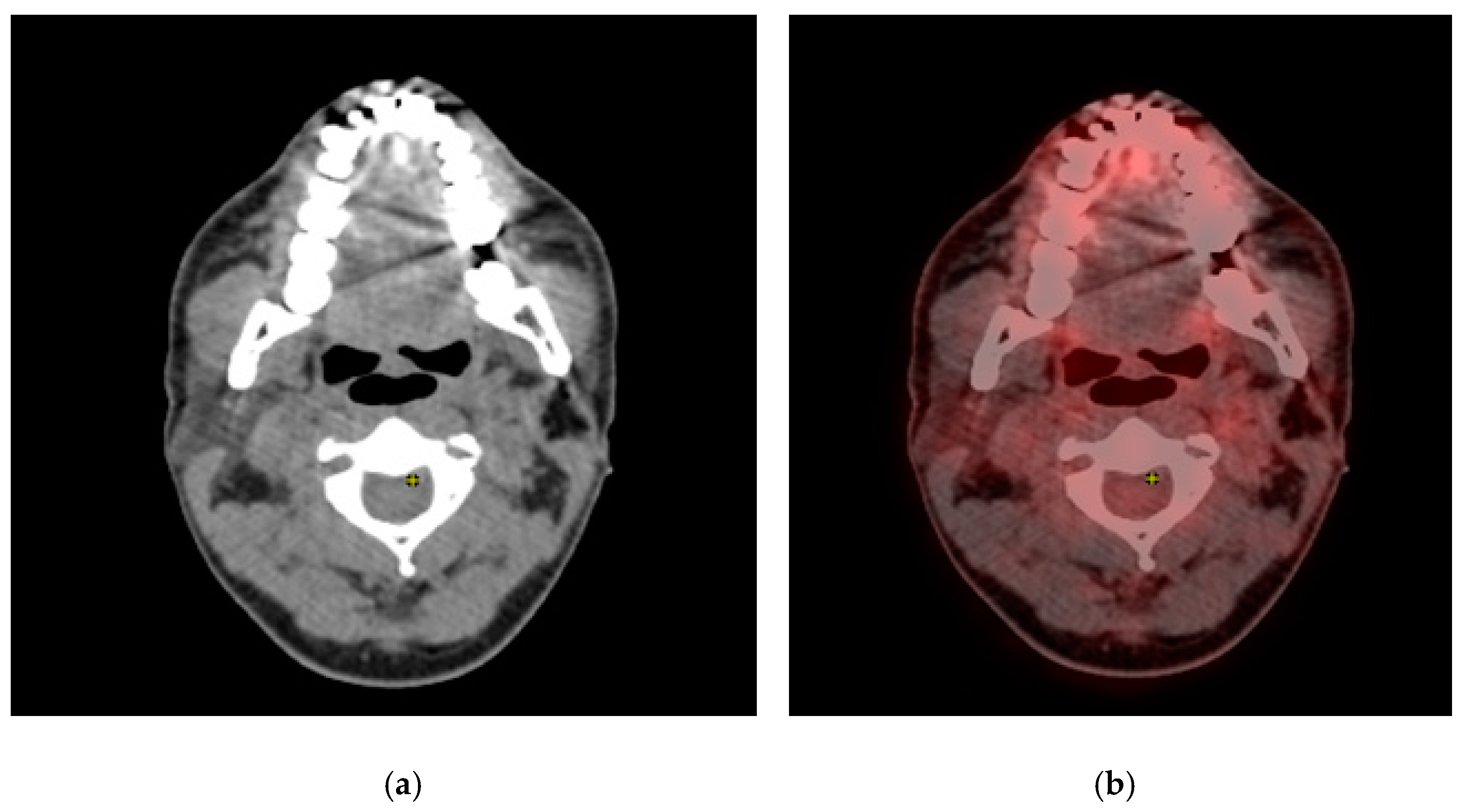
Even then, PET-CT might show false positive results in a review patient who poses diagnostic confusion. One such case is presented here: A 58-year-old male patient was diagnosed and treated for salivary gland ductal carcinoma by surgery and radiotherapy one year prior to this event. In the review CT, brain metastasis was evident. A PET-CT was advised immediately, and PET-CT revealed metastasis to the lung nodules as well.
In addition to the signals in the metastatic nodules, a well-defined positive signal was evident in the submental region (
Figure 10a,b). Upon clinical correlation, there was no evidence of a sign of metastasis in the submental region. This might be confused with a metastatic involvement, thus representing a pitfall.
This review briefly compiles the artifacts and diagnostic inhibitions/restrictions in head and neck imaging. Little software has been developed to reduce metal-induced artifacts, but its usage is limited and not accessible. Metal artifact reduction software (MARs) has been tested in phantom experiments with dental implants using mono-energy (MonoE) CT images, and it was found that a combination of MonoE and MARs reconstruction was the best method for reducing metal artifacts. This study had some major limitations [
14].
5. Conclusions
The advanced imaging in the head and neck region has greatly lifted the quality and efficiency of the diagnosis and treatment planning of pathologies. As new techniques and software are being introduced, their availability and accessibility are considerably lower. Even after advancements in imaging, these modalities have their pitfalls and diagnostic inhibitions. This paper attempts to address these from a maxillofacial physician and radiodiagnosis point of view, which can be used by physicists for the development of more accessible software and technical alterations to reduce these issues.


