Abstract
As the main functional element of the fuel cell, the bipolar plate ensures the functions of media distribution, electron conduction, and mechanical stability of the entire fuel cell stack. Currently, metallic bipolar half-plates are manufactured using clocked, shaping processes (stretch forming). A transfer to a continuous forming process, such as incremental hollow embossing using rollers, promises a significant increase in productivity and, thus, profitability. Based on experimentally determined material parameters, a realistic forming simulation was set up. Significant evaluation parameters are geometric accuracy, sheet thinning, and springback. In addition, specific requirements for the manufacturing equipment have to be derived.
1. Introduction
The Reduction of greenhouse gases and the independence from fossil fuels are major challenges for the economy. In addition to expanding the generation, transmission, and storage of electrical energy, hydrogen can also play an important role in this transition. Hydrogen offers a high level of flexibility in generation, transport, and storage [1]. The fuel cell is the most efficient energy converter for the reconversion of hydrogen and for the generation of thermal energy since the chemical energy is converted directly and without the detour via mechanical energy [2].
The main representative of fuel cells is the so-called proton-exchange membrane fuel cell (PEMFC). An essential component of these fuel cells is the bipolar plate, which, in addition to media distribution and electron conduction, also ensures mechanical stability. In order to make the fuel cells suitable for the mass market, components like the bipolar plates must be able to be manufactured in a highly productive manner. Various institutions are working on component manufacturing with high production capabilities [3,4]. Continuous processes promise the highest productivity increase, which is why the technology design of metallic bipolar plates made of stainless steel by incremental hollow embossing using rollers is presented in this article.
Cost and space-efficient fuel cells have very thin bipolar plates with foil thicknesses down to 75 µm [1]. Within the HZwo: Frame research project, the research partners have set themselves the task of being able to produce bipolar plates with just 50 µm. An embossing process, which forms such a thin material, must be designed very precisely in order to avoid wrinkles, cracks, but also under-formed areas. Starting with the recording of the data from the used material, through to the depiction of boundary conditions close to the process, a large amount of data must be considered for the process simulation with Simufact Forming 2021. The methodology for designing such a hollow embossing process using rollers is set out below.
2. Material
The specific properties of hydrogen place high requirements on the used materials and their processing. The ability to diffuse requires, for example, reliable gas-tightness of the components in order to avoid losses and the risk of explosion and fire from escaping hydrogen. Many metals can be penetrated by hydrogen atoms (permeation). Corrosion can lead to premature material fatigue (degradation) and thus to cracking and brittle fracture. Stainless steels designed for the application can permanently resist permeation and degradation. Components that come into contact with hydrogen are therefore made of austenitic stainless-steel grades 1.4307, 1.4435, and 1.4404 [5].
In the research project presented here, bipolar plates with stainless steel of the quality 1.4404 (316L, DIN X2CrNiMo17-12-2) with a thickness of 50 µm are used. This material can be easily cold-formed and welded. The resistance to intergranular corrosion is not affected by the heat input during welding. Due to its high mechanical stability, this stainless steel is suitable for the support function of bipolar plates in fuel cell stacks.
Coating processes are used with metallic bipolar plates in order to improve the electrical contact and, at the same time, further improve the corrosion resistance to the various media, such as the accruing water or the coolant. In principle, a coating can be applied at various points in the production process of the joining process of bipolar plates in order to improve the electrical contact. There are process variants with coated coils and coating processes before or after the forming process. In our manufacturing process, the coating takes place after the forming process and a cleaning process. A titanium buffer and carbon functional layer are applied as a coating by means of electron beam evaporation.
First of all, existing material data from Simufact’s own program database was used for the numerical simulation. In order to calibrate the model, material parameters were experimentally recorded with the real base material. The flow curve, the anisotropy values, and the forming limit were selected as essential material parameters. The flow curve can be determined with the help of hydraulic deepening tests. The forming limit curve is determined using Nakajima tests (Figure 1). In addition, the anisotropy values were determined by means of tensile tests. The material characterization was carried out with the help of our project partner Vitesco Technologies Group AG.
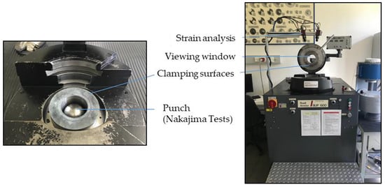
Figure 1.
Material testing machine ZwickRoell GmbH & Co. KG BUP 600, Ulm, Germany (in use at the Technical University Freiberg) [Vitesco Technologies Group AG].
An overview of the test parameters for the Nakajima Test and the Bulge Test is shown in Table 1. A square pattern (1 × 1 mm²) was applied to be measured using the AutoGrid optical measuring system.

Table 1.
Comparison of test parameters—Nakajima Tests and Bulge Tests.
2.1. Forming Limit Curve FLC
To determine the different stress states, the values were recorded with different specimen geometries with three repetitions. For steel materials, according to the standard (DIN EN ISO 12004), the recess direction perpendicular to the rolling direction is recommended. The lubrication corresponds to production by first cleaning the sheets and then applying a light film of lubricating oil. This film was blown off with compressed air to avoid oil accumulation.
The FLC (Figure 2) is an indicator of damage occurring during the forming process. The abscissa axis (X) represents the minor strain, while the major strain is plotted on the ordinate (Y). The limit values were determined in order to mark the maximum deformation. In comparison to the classic literature, a narrower range of the minor strain was examined. This is possible due to the dominant stretching. The deep-drawing area has, therefore, not been studied as much. The shape suggests that a broader range of investigation leads to the classic form of FLC.
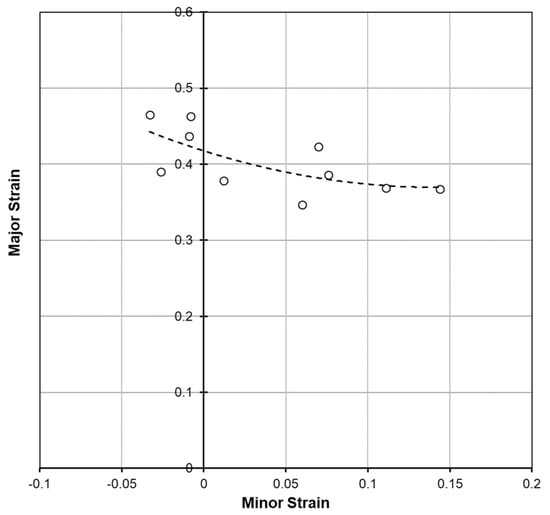
Figure 2.
Computed forming limit curve for 1.4404 with a thickness of 0.05 mm [Vitesco Technologies Group AG].
2.2. Flow Curve
At low temperatures (20 °C), the forming rate of up to 40 1/s is of minor importance in steel [6]. Therefore, the tests were carried out quasi-statically. The equivalent strain-rate is in the range of approx. 30 to 50 1/s. The stress and strain values were recorded and recalculated as a flow curve using a tabular conversion. The effective plastic strain (φv) is shown on the abscissa axis and the yield stress (kf) on the ordinate axis—Figure 3. All three curves are almost identical, so it shows a high level of reproducibility. The tensile strength has a maximum value of 595 Mpa and the yield strength of 280 MPa.
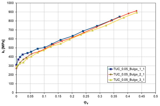
Figure 3.
Calculated flow curve for 1.4404 with a thickness of 0.05 mm [Vitesco Technologies Group AG]—the colors show different repetitions.
2.3. Anisotropy Values
Parallel to the uniaxial tensile tests to determine the anisotropy; three reference tests were also performed with the different sample orientations (0°; 45°; 90°). The r-values for the vertical anisotropy were calculated based on the measurement results and averaged over the three reference tests, as shown in Table 2. The measurement was performed using an optical video-extensometer. The tests were carried out with sheets measuring 110 mm × 20 mm × 0.05 mm and a crosshead speed of 2 mm/min.
Table 2.
Average r-values for 1.4404 with a thickness of 0.05 mm [Vitesco Technologies Group AG].
3. Process Simulation
The first simulative and experimental attempts to shape bipolar plate geometries using rollers had already been carried out and published before the current research project [7]. As part of the preliminary project HZwo: BiP, important findings were summarized [8]. Building on this scientific knowledge, the focus in the current research project was to focus on a complex bipolar plate geometry and, at 50 µm sheet thickness, comparatively very thin stainless-steel foils and realistic boundary conditions. The design of the bipolar plate (surfaces, radii, media distributor, …) was developed in cooperation with Vitesco Technologies Group AG and provided by our project partner as a CAD file for process simulation. First, the already presented material data was implemented in the Simufact program. The material card for 1.4404 316L from the Matilda material database serves as the basis for this. Since the forming energy is very low, the component is very thin and has very little mass compared to the relatively large tool rolls; thermal effects are not considered.
The Coulomb friction model was selected to represent the friction properties. Prior to the rolling process, the deep-drawing process was already examined. Due to this examination, the value for deep drawing is a coefficient of 0.12. An additional lubrication was used. But in the opposite to conventional deep drawing processes, where lubrication leads to less friction/ friction coefficients, an improvement of friction could not be observed for all attempts with foil in 50 µm sheet thickness. In order to take this observation into account and to create a safety margin, a friction coefficient of 0.15 was selected.
For a sufficiently precise discretization of the workpiece geometry, the sheet-mesher for solid-shell elements was applied with an edge length of 0.25 mm and 5 elements in the thickness direction of the sheet. The sheet metal has dimensions of 100 mm × 50 mm × 0.050 mm. Due to the component size, this results in a number of 80,000 elements. The embossing rollers were implemented in the simulation model as rigid bodies with a surface mesh. In principle, the fine bipolar plate geometry would have to be meshed more finely. Since a statement for the entire formability should be derived and formed areas influence the areas still to be formed, it was not possible to reduce the computational effort in this way. For reasons of computing time, remeshing was also dispensed with.
As in a rolling mill, the kinematics were designed in such a way that the sheet metal is pulled through the rollers and held tense. The tension can be varied, i.e., the beginning and end of the sheet metal sample. The tensile stresses applied are significantly smaller than the yield stresses. This boundary condition does not artificially stiffen the sheet metal part.
The movement of the embossing rollers is shown on the embossing image—Figure 4. The forming process is run with the target parameter in terms of the forming speed. The embossing rollers rotate at 60 revolutions per minute. Due to the roll diameter (approximately 105 mm), the strip feed is 0.33 m/s.
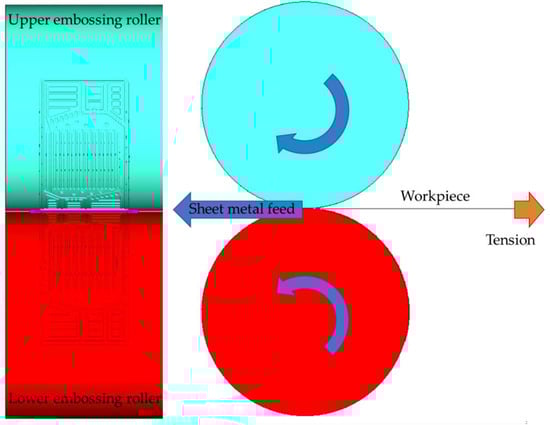
Figure 4.
Simulation model view with component movement.
At the end of the forming process, the embossing rollers and the strip guide must be released in order to be able to evaluate the amount of springback. After preparing the two mentioned stages of the process in the preprocessor, the model has to be solved. In order to minimize the calculation time, the DDM (Domain Decomposition Method) parallelization function is used, which enables the calculation model to be divided between different processor cores. Due to the stability of the calculation and the sufficiently precise meshing, remeshing was not used. Due to the described parameters and model properties, a calculation time of approx. 80 h results.
4. Results
The geometry of the bipolar plates could be shaped successfully by the simulation model. The specific areas, which are marked in Figure 5, differ significantly in their geometry.
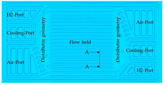
Figure 5.
Accuracy of mapping of the bipolar plate geometry.
From a technological point of view, it is a stretching of the sheet metal foil. This means that the bipolar plate geometry is only drawn to a small extent from the edge areas. The shaping mainly results from the thinning of the sheet metal. This thinning of the sheet metal foil is the decisive technological limit for the production of complex geometries since no cracks are allowed to appear in the series process. An even thinning is, therefore, the desired goal. The thinning can be controlled within certain limits with the help of the channel and distributor geometry (channel width, length, depth, and radii).
Since it is mainly a stretching process, the thinning can be roughly determined in advance. For this purpose, the distance between the grooves of the flow field and the unwounded length of these were determined in the CAD contour—Figure 6. As a result, a thinning of around 18.8% change in length/groove spacing can be expected in the area of the flow field.
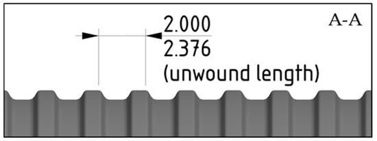
Figure 6.
Sketch of the flow field with groove spacing and unwounded length.
The thinning of the metal foil of the whole bipolar plate is up to 22% (Figure 7) in the areas of high contour formation. These areas are not in the flow field but in the distributor geometry. For a foil with a thickness of 50 µm, this means a remaining material thickness of approx. 39 µm. This value is just within the target range so as not to overstrain the foil. Even greater thinning in narrow areas would indicate a sensitivity to cracking due to a large-meshed model compared to the very fine geometric elements. The predicted thinning in the river field was not quite achieved at around 10 to 15%.
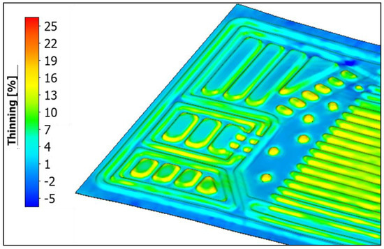
Figure 7.
Thinning of the shaped bipolar plates.
In the contour areas with relatively high material thinning, the forming limit is up to 60% utilized. Since narrow areas with high gradients are also difficult to interpret in this evaluation due to the mesh properties, a tendency to crack formation at the high geometric elements can also be determined in the case of the forming limit—Figure 8. In the area of the media ports, which are removed anyway after the forming process, this is irrelevant. Because of the low target geometry, the flow field can also be regarded as non-critical in this regard. However, the distributor geometry, which is located between the flow field and the media distribution, must be free of cracks after the forming. After the simulation, the target geometry can be produced using embossing rollers. In order to be able to reshape the areas of high thinning even better, a further adjustment of the flow distributor would be advisable. However, a final assessment of this technology requires experimental validation.
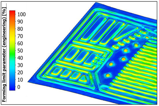
Figure 8.
Utilization of the forming limit of the metal foil.
5. Outlook
The material model is basically verified. For a comprehensive verification of the whole simulation model, real experiments with embossing rollers have to be carried out. In addition, these experiments can be used to show significantly higher productivity compared to classic embossing on the deep-drawing press. Verification of the process requires further steps beyond the forming itself. The rollers must be precisely aligned mechanically and controlled synchronously. In addition, the cutting process is also challenging with such thin foils.
Furthermore, the simulation of a very small area of a typical bipolar plate geometry (parts of the manifold geometry and the flow field) can be used to study fine meshes and their impact on the results.
In order to be able to generate simulation models for a wide range of applications, the investigation of other foil thicknesses and related stainless steel materials are also necessary.
6. Conclusions
According to the forming simulation, complex bipolar plate geometries can be produced with an embossing process using rollers. For this purpose, various material parameters of the stainless-steel foil used, such as the flow curve, the anisotropy, and the forming limit were experimentally determined. A forming simulation was set up under realistic conditions, i.e., clamping, friction, and forming conditions. As a result, the shape of the bipolar plate geometry could be shown. The completed bipolar plate shows no cracks, creases, or insufficiently formed areas. However, there are conspicuous areas in the distributor geometry that require experimental verification.
Author Contributions
Conceptualization, M.F.; methodology, M.F. and K.K.; validation, M.F. and K.K.; investigation M.F. and K.K.; writing—original draft preparation, M.F.; writing—review and editing, K.K.; supervision, B.A.; project administration M.F. and K.K. All authors have read and agreed to the published version of the manuscript.
Funding
This research was funded by Europäischer Fonds für regionale Entwicklung (EFRE)/Sächsische Aufbaubank (SAB), grant number 100362053, as a part of the cooperative project Hzwo:FRAME VP1.1. The publication of this article was funded by the Chemnitz University of Technology. The financial support is gratefully acknowledged.
Institutional Review Board Statement
Not applicable.
Informed Consent Statement
Not applicable.
Data Availability Statement
The data that support the findings of this study are available from the corresponding author upon reasonable request.
Acknowledgments
The authors gratefully acknowledge the following researchers and project partners for their valuable contributions in performing the basic methodology of manufacturing metallic bipolar plates and valuable contributions in performing various material characterization analyses: Alexander Bauer (former employee of Group of Virtual Production Engineering (ViF), Chemnitz University of Technology, 09125 Chemnitz, Germany) for basic investigations in the production of metallic bipolar plates; Thomas Müller (Vitesco Technologies GmbH, Siemensstraße 12, 93055 Regensburg, Germany) for the provision of material data.
Conflicts of Interest
The authors declare no conflict of interest.
References
- Töpler, J.; Lehmann, J. Wasserstoff und Brennstoffzelle. Technologien und Marktperspektiven, 2nd ed.; Springer: Berlin/Heidelberg, Germany, 2017. [Google Scholar]
- Tschöke, H.; Gutzmer, P.; Pfund, T. Elektrifizierung des Antriebsstrangs. Grundlagen—Vom Mikro-Hybrid zum Vollelektrischen Antrieb, 1st ed.; Springer Vieweg: Berlin, Germany, 2019; pp. 99–107. [Google Scholar]
- Müller, C.; Janssen, H.; Brecher, C. Hot Forming of Metallic BipolarPlates Using Conductive Heating. In Proceedings of the FC3 Fuel Cell Conference Chemnitz, Chemnitz, Germany, 31 May–1 June 2022; Universitätsverlag Chemnitz: Chemnitz, Germany, 2022; pp. 175–182. [Google Scholar]
- Porstmann, S.; Polster, S.; Reuther, F.; Melzer, S.; Nagel, M.; Pstk, K.; Dix, M. Zielgrößen und Spannungsfelder beim Vergleich von Herstellungsverfahren für metallische Bipolarplatten. In Proceedings of the FC3 Fuel Cell Conference Chemnitz, Chemnitz, Germany, 31 May–1 June 2022; Universitätsverlag Chemnitz: Chemnitz, Germany, 2022; pp. 195–208. [Google Scholar]
- Hobohm, M. Werkstoff der Wahl für grünen Wasserstoff. 2022. Available online: https://umformtechnik.net/umform/Inhalte/Fachartikel/Werkstoff-der-Wahl-fuer-gruenen-Wasserstoff (accessed on 23 September 2022).
- Doege, E.; Behrens, B.-A. Handbuch Umformtechnik, 3rd ed.; Springer Vieweg: Berlin, Germany, 2016; pp. 93–97. [Google Scholar]
- Bauer, A.; Härtel, S.; Awiszus, B. Manufacturing of Metallic Bipolar Plate Channels by Rolling. J. Manuf. Mater. Process. 2019, 3, 48. [Google Scholar] [CrossRef]
- Bauer, A. Experimentelle und numerische Untersuchungen zur Analyse der umformtechnischen Herstellung metallischer Bipolarplatten. Ph.D. Thesis, University of Technology Chemnitz, Chemnitz, Germany, 5 December 2019. [Google Scholar]
Publisher’s Note: MDPI stays neutral with regard to jurisdictional claims in published maps and institutional affiliations. |
© 2022 by the authors. Licensee MDPI, Basel, Switzerland. This article is an open access article distributed under the terms and conditions of the Creative Commons Attribution (CC BY) license (https://creativecommons.org/licenses/by/4.0/).