Abstract
Modern car bodies are constantly relying on higher proportions of high- and ultra-high-strength steels. In the past, the increase in material strengths led to a conflict regarding the complexity of component geometries. Limits of material formability were reached, and compromises had to be made in part design. By integrating application-oriented problems into the material development, these limits are expanded with respect to the given requirements. Within the present study, for three dual-phase steels with a tensile strength of 800 MPa, practical laboratory tests are presented and their benefits in component manufacture are discussed. In particular, the material ductility has an essential role for the forming process.
1. Introduction
Modern car bodies are constantly relying on higher proportions of high- and ultrahigh-strength steels. In the past, the increase in material strength led to a conflict regarding the complexity of the component geometries. Limits of material formability were quickly reached, and compromises had to be made in component design. Through new approaches in material development and the integration of application-oriented problems, these boundaries are now significantly expanded. However, to select materials according to the requirements, the special features must be measurable and the associated benefits in component design and production must be implemented in the development process.
As a rule, the elongation or the forming limit curve is an essential feature for the formability of a material, representing the global formability or the resistance to instability. In feasibility analyses using Finite Element Method (FEM), these characteristics are constantly used. In press shops, the simple rule with higher elongation values, more complex part geometries or higher process stability can be ensured. However, practical experience shows that local forming behavior often limits process reliability. Thus, the stretch flangeability of the blank edges is significantly influenced by the previous mechanical cutting process. These local properties can be still not sufficiently considered for the part design in FEM simulation. The interaction of the influencing parameters is complex and can only be estimated by statistical considerations.
The aim of the present study is to work out extended material characteristics of dual-phase steels (DP) with 800 MPa tensile strength for an efficient selection and secure processing in the press shop. Therefore, existing information is gathered and enhanced by additional material testing. In a further chapter it is discussed how to transfer these laboratory results to process design for press shop application.
2. Materials: Dual-Phase Steels with Tensile Strength of 800 MPa
According to VDA 239-100 [1], a “classic” and a “ductility high” (DH) variant with improved elongation are defined in the 800 MPa class of DP-steels. Thyssenkrupp Steel Europe AG also offers a High Hole Expansion version (HHE) [2]. The different characteristics of the three DP800 variants are obvious, as shown in Table 1.

Table 1.
Representative mechanical properties of the DP800 steel grades (average values).
A first orientation regarding the formability properties is represented by local elongation at fracture (TFS) vs. uniform elongation (UE) according to Hence [3,4,5]. In the present study the local elongation at fracture (eps3f) instead of the true logarithmic fracture strain (TFS) according to [6] is used, as given in Equation (1), whereby the local elongation at fracture (eps3f) refers to the maximum sheet thickness reduction over the fracture surface of the tensile specimen. For a larger quantity of material batches, the eps3f values and the corresponding UE is given in Figure 1.
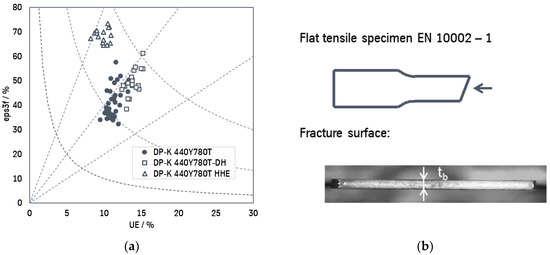
Figure 1.
(a) Local and global forming potential of DP800 steel grades (test direction longitudinal); (b) measurement procedure eps3f.
The DH variant is arranged with an average higher uniform elongation level and simultaneous higher eps3f values above the classic variant. On the other hand, the HHE variant offers even higher eps3f values, but with a slightly reduced uniform elongation level. From the diagram in Figure 1, the following expectations can be derived from the Classic variant:
- DP-K 440Y780T-DH: Improved balanced local and global formability
- DP-K 440Y780 HHE: Optimized for local formability
As described by [7], there is a statistically relevant correlation of eps3f. However, the local forming properties from the fracture surface measurement cannot be calculated directly from the eps3f values for values such as the hole expansion ratio (HER) according to ISO 16630 [8] or the maximum bending angle according [9]. The eps3f classification provides an orientation or expectation for the local formability of the material.
As can be expected from UE in Table 1, the three variants show differences in the work hardening behavior. Figure 2 shows the hardening behavior measured according to DIN EN ISO 6892 [10]. In [1], a minimum n-value (longitudinal) of >0.15 is specified for DP800 classic in a strain range of 4% and 6%. Normally the standard strain range for the determination of the n-value is from 10% strain up to UE.
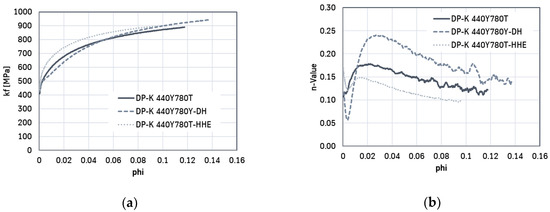
Figure 2.
(a) Work hardening curves and (b) incremental n-values (longitudinal; quasi-static) of the DP800 grades.
For a better understanding of the different hardening behavior of the three material concepts, internal FEM investigations have been carried out (Figure 3). Analyzing the state close to necking it is noticeable that the HHE concept reaches the same drawing depth like the “Classic” concept. Beside this the strain distribution is completely different. So the different strain hardening, especially for low strains of the DP concepts, shows impact on the strain distribution. For the FEM studies the boundary conditions like friction and yield criteria was kept identical; yield locus and flow curve have been fitted to the experimental values.
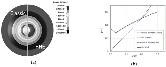
Figure 3.
FEM studies of the Limited Dome Height (LDH) test using a hemispherical punch: (a) major strain upper surface close to necking 33 mm drawing depth; (b) Strain path DP-K 440Y780T and DP-K 440Y780T HHE of the critical element.
3. Stretch Flange Formability—Test Method & Test Results
To evaluate the stretch-flangeability of cutting edges, additional hole expansion tests with varying test conditions compared to the ISO hole expansion test are carried out to describe the failure as comprehensively as possible. Table 2 gives an overview on the test program.
Table 2.
Overview test program: investigation target, procedure and boundaries.
Initially, the standard test is an in-plane hole expansion using a Marciniak tool. In test run 1 the material-side scatter due to the local micro structural differences is considered by a high number of different batches. The mean value of the hole expansion minus the standard deviation is determined as the material-specific limit (Figure 4). Especially in typical applications of cold-rolled dual-phase grades, the critical edge strain is often in the flange area with a low orthogonal strain gradient [11,12]. Nevertheless, to evaluate the influence of the orthogonal strain gradient, in test runs two additional hole expansion tests with different conical punches with opening angles of 120° and 50° (Figure 5) have been carried out. The mechanical cutting conditions are kept identical.
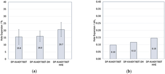
Figure 4.
In-plane hole expansion test; ∅20 mm holes, cutting clearance 11–13%, testing >48 h after punching the holes: (a) typical mean values HER from several coils [%] (b) HER minimum: Mean value—standard deviation (SD), phi1 [-].
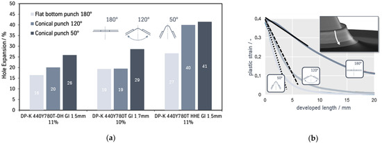
Figure 5.
(a) Hole expansion ratio using different punch geometries; ∅20 mm; cutting clearance 10–11%, testing >48 h after stamping; hole expansion converted to the sheet mid layer after Equation (2); (b) schematic illustration orthogonal strain gradient.
The higher hole expansion ratio for the HHE concept is obvious in all test conditions. Looking at the influence of the orthogonal strain gradient at the cutting edge the higher HER values for conical punch geometries has been detected. By using conical punches, a higher orthogonal strain gradient is achieved [9,12]. A higher strain gradient is also typical for the standard hole expansion according to ISO16630 [4], which is usually the most popular test for comparing edge crack sensitivity.
Cutting edges with local high strain levels have a high aging potential, so that the time interval between the punching process and the following forming operation has a significant influence on the failure level [13]. Extra tests are carried out directly after punching the holes (<10 min) to estimate the effect of ageing on the hole expansion ratio. The higher HER values for a smaller time interval could be observed in test run 3 (Figure 6a). In the standard procedure for the hole expansion tests, the critical case is assumed, so that a minimum time of 48 h between punching and hole expansion is always used.
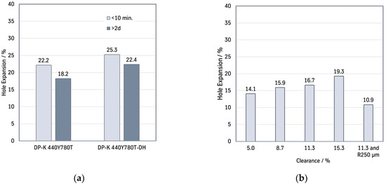
Figure 6.
In-plane hole expansion ratio (Marciniak tool) ∅20 mm holes: (a) Testing <10 min. and >48 h after punching, cutting clearance 11–13%; mean value from 10 resp. 4 coils; (b) HER for DPK 440Y780T-DH 1.5 mm using different cutting parameter (clearance [%] and tool radii [µm]).
Another important aspect is the parameters of the cutting process itself. They have been investigated in test run 4. Here the standard cutting clearance of 11–13% (referring to sheet thickness) comparable to ISO hole expansion is compared to different punching parameters as shown in Figure 6b. The influence of tool wear is also investigated by using defined tool edge radii of R250 µm. This radius represents the worn cutting tool and leads also to a significant loss of edge formability.
The last parameter considered in test run 5 is the effect of the rolling direction respective anisotropy. On real part geometries, the strain at the blank edges is aligned in a certain orientation to the rolling direction. To measure the effect on the failure limit, special halved samples with a 1 mm grid for strain measurement are used. The middlepunched hole expansion sample is split in the requested test direction (L/T/D) before the test, so that there is a strain localization in the two concave areas (Figure 7). The reduced forming potential for transverse load is given in Figure 8a.
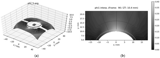
Figure 7.
Test setup for measuring the rolling direction dependent edge strain using the Marciniak tool: (a) measuring points for determining the edge strain; (b) top view evaluation of local edge strain and strain gradients (phi1).
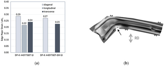
Figure 8.
(a) Hole expansion test with halve split blanks and strain measurement; clearance 11%; testing >48 h after stamping; (b) Example: Local edge strain distribution of an A-pillar reinforcement part (demonstrator tool tkSE).
To give some advice for tool making regarding how to use the investigated effects, the resulting HERs are converted to logarithmic strain, as are mainly used in FEM feasibility studies. Table 3 gives an overview of the interaction of the individual effects which can be transferred to critical areas in real geometries as the A-pillar reinforcing part in Figure 8b. The result is a recommendation for the design of the forming processes in the form of a maximum edge strain (major strain, phi1).
Table 3.
Consideration of the processing boundary conditions to the stretch-flangeability of cutting edges, compare to Figure 8b.
4. Advantages in Part Design
Press trials using a demonstrator tool representing an A-pillar reinforcement show that the named product advantages are directly applicable. In the forming simulation of the part, critical areas are identified in the feasibility analysis with a DP800 classic. By geometric adjustment, such as an increase of the radii, the areas can be sufficiently optimized regarding process safety. However, this can only be done to a certain limit. Changes in production can also occur if the design is close to the maximum limit shape. A higher quality, such as the DP-K 440Y780T-DH in this example, can minimize the forming and production risks or lead to stable part production. Improved forming properties make it possible to produce more complex part geometries.
To evaluate the standardized hole expansion results, as described above, on a complex geometry, a trimming tool has been designed for the demonstrator A-pillar reinforcement with which laser blanks can be mechanically shear cut in the concave corner area of the part geometry (Figure 9). The hole diameters have been designed with ∅25, ∅50 and ∅100 mm to be able to load different edge strain conditions.
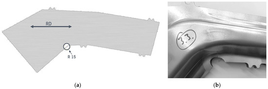
Figure 9.
Demonstrator tool A-pillar reinforcement (a) laser-cut blank with local recutting area; (b) critical edge cracking area.
The experimental investigation shows that the process is much less critical in terms of edge failure than originally assumed. The hole expansion results shown above consider the most important parameters. In the tool design, the global hole expansion values were used as a guideline. Only after significant adjustment of the diameter and displacement of the trimming geometry was it possible to provoke an edge failure in the experiment on the demonstrator geometry.
To better understand the working range or the representation of the edge behavior, a series of tests with a DP-K 440Y780T in 1.5 mm was carried out. The material achieved 13% in the in-plane hole expansion test using the standard Marciniak tool. The tests have been analyzed with FEM simulation and important test parameters have been adjusted. These include the blank position to the rolling direction (major strain is oriented to the rolling direction), consideration of edge ageing (time between punching and forming), analysis of the local sheet thickness reduction in the critical area and accurate documentation of the blank position when inserting.
In addition, hole expansion tests were carried out with a strain measurement to analyze the maximum local strain distribution at the edge. However, no significant localization could be recorded here. The maximum values of phi1 = 0.14 are only slightly above the global hole expansion values of 13%.
The FEM simulation, using standard parameters, results in significantly higher values in the range of phi1 > 0.3 for the edge strain in the critical area (Figure 9). By using material data adjusted to the mechanical properties of the both DP concepts the influence on the local strain distribution becomes obvious. However, the values are significantly higher than the laboratory values from the hole expansion test as shown in Figure 10. The focus of the analysis was the influence of mesh size and material model, as well as the evaluation of the edge crack sensitivity based on the strain gradient. A proper fitted and validated material model is basis for these investigations [14], as rudimentary fitted material models, e.g., Swift or Hill ’48, led to misinterpretations. In this case the yield curve was fitted to higher strains via the hydraulic bulge test and the yield locus was also adjusted to equibiaxial flow stress by the bulge test.
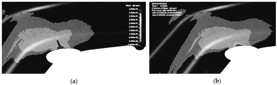
Figure 10.
Demonstrator tool A-pillar reinforcement FEM analysis 1 mm mesh size (a) DP-K 440Y780T (b) DP-K 440Y789T-DH.
5. Summary and Conclusions
Experience in the recent past shows that the process reliability of ultra-high-strength dual-phase steels is mainly influenced by the local formability and the forming capacity of the cutting edges. Up to now, it has been difficult to make an accurate failure prediction by FEM for the cutting edges [15]. In the described studies, the most important influencing variables on the complex failure on cutting edges and a pragmatic approach for estimating the forming potential were shown. New optimized material concepts can help to design the forming processes more robustly in terms of materials. Here, it is necessary to weigh up between global and local forming potential. Tests on a practical part demonstrator show that the failure level in this individual case is assessed too conservatively and that there is still a need for further research about edge failure criteria.
Author Contributions
Conceptualization, S.S. and M.L.; investigation, T.B. and S.W.; writing, S.W. and T.B. All authors have read and agreed to the published version of the manuscript.
Funding
This research received no external funding.
Institutional Review Board Statement
Not applicable.
Informed Consent Statement
Not applicable.
Conflicts of Interest
The authors declare no conflict of interest.
References
- Standards Committees. VDA 239-100: Flacherzeugnisse aus Stahl zur Kaltumformung/Sheet Steel for Cold Forming (Version 06/2016); Standards Committees: Berlin, Germany, 2011. [Google Scholar]
- Dual-Phase Steels—Tailored Portfolio for Modern Lightweight Construction. Available online: https://www.thyssenkrupp-steel.com/en/products/sheet-coated-products/multiphase-steel/dual-phase-steel/ (accessed on 1 August 2020).
- Hance, B.M.; Link, T.M. Effects of Fracture Area Measurement Method and Tension Test Specimen Type on Fracture Strain Values of 980 Class AHSS. In IOP Conference Series: Materials Science and Engineering; IOP Publishing: Bristol, UK, 2019; Volume 651, p. 012061. [Google Scholar]
- Hance, B.M. Practical Application of the Hole Expansion Test. SAE Int. J. Engines 2017, 10, 247–257. [Google Scholar] [CrossRef]
- Hance, B.M. Advanced High Strength Steel: Deciphering Local and Global Formability. In Proceedings of the International Automotive Body Congress, Dearborn, MI, USA, 28–29 September 2016. [Google Scholar]
- Heibel, S.; Dettinger, T.; Nester, W.; Clausmeyer, T.; Tekkaya, A.E. Damage Mechanisms and Mechanical Properties of High-Strength Multiphase Steels. Materials 2018, 11, 761. [Google Scholar] [CrossRef] [PubMed]
- Larour, P.; Freudenthaler, J.; Weissböck, T. Reduction of cross section area at fracture in tensile test: Measurement and applications for flat sheet steels. J. Phys. Conf. Ser. 2017, 896, 012073. [Google Scholar] [CrossRef]
- Standards Committees. International Standard ISO 16630: Metallic Materials–Sheet and Strip–Hole Expanding Test; Standards Committees: Berlin, Germany, 2017. [Google Scholar]
- Standards Committees. VDA 238-100: Plättchen-Biegeversuch für Metallische Werkstoffe/Plate Bending Test for Metallic Materials (Version 07/2020); Standards Committees: Berlin, Germany, 2020. [Google Scholar]
- Standards Committees. DIN EN ISO 6892-1: Zugversuch, Prüfverfahren bei Raumtemperatur für metallische Werkstoffe; Standards Committees: Berlin, Germany, 2016. [Google Scholar]
- Beier, T.; Woestmann, S. Berücksichtigung von schergeschnittenen Blech-kanten zur Auslegung von Formgebungsprozessen höherfester Stahlwerkstoffe in der FEM-Umformsimulation. In Proceedings of the 14th German LS-DYNA Forum, Bamberg, Germany, 10–12 October 2016. [Google Scholar]
- Iizuka, E.; Urabe, M.; Yamasaki, Y. Effect of strain gradient on stretch flange deformation li-mit of steel sheets–Prediction method of cut edge failure. In Proceedings of the Umformen im Karosseriebau, Bad Nauheim, Deutschland, 29–30 September 2015. [Google Scholar]
- Atzema, E.; Seda, P. Effect of zinc coating and time on edge ductility. In Proceedings of the 5th International Conference on Steels in Cars and Trucks, Amsterdam, The Netherlands, 18–22 June 2017. [Google Scholar]
- Iizuka, E.; Hashimoto, K.; Kuwabara, T.; Ishiwatari, A.; Inazumi, T. Effects of anisotropic yield functions on the accuracy of forming simulations of hole expansion. Procedia Engineering 2014, 81, 2433–2438. [Google Scholar] [CrossRef]
- Braun, M.; Atzema, E.; Beier, T.; Bülter, M.; Brockmann, S.; Larour, P.; Müller, T.; Neuhaus, R.; Richter, A.; Schneider, M. Umformsimulation unter Einbeziehung einer verminderten Umformbarkeit schergeschnittener Stahlblechkan-ten–Wirksamkeit von 3 verschiedenen Kantenriss-Kennwerten und 3 Software-Systemen im Realversuch. In Proceedings of the Umformen im Karosseriebau, Bad Nauheim, Deutschland, 28 September 2016. [Google Scholar]


Publisher’s Note: MDPI stays neutral with regard to jurisdictional claims in published maps and institutional affiliations. |
© 2022 by the authors. Licensee MDPI, Basel, Switzerland. This article is an open access article distributed under the terms and conditions of the Creative Commons Attribution (CC BY) license (https://creativecommons.org/licenses/by/4.0/).