1. Introduction
The advent of 3D-printing technology offers a wide range of opportunities for the development of robotic systems, especially in the context of engineering education. This technology allows for rapid prototyping, easy modification of the structure and restoration of damaged parts, making it suitable for use in student education. Compared to industrial robotic systems, which require significant investment and specialized training, 3D-printed solutions offer an affordable and flexible alternative for learning the basic principles of robotics.
There are a number of studies aimed at developing low-cost robotic manipulators and their application in educational environments. In Ref. [
1], a five-axis manipulator designed to perform “pick and place” tasks is presented.
The Helene robot [
2] offers a modular design with six degrees of freedom and options for integration with the Robot Operating System (ROS). Other studies consider educational applications of robotics, communication aspects in remote control [
3], and the use of 3D modeling and analysis in the development of robotic systems [
4]. The importance of 3D printing for engineering education is discussed in [
5], where its role in developing practical skills and engineering thinking is emphasized.
Additional applied research extends the context to specialized gripping mechanisms, motion algorithms, and remote laboratory environments. In Ref. [
6], the ability of a servo-electric gripper to adjust the gripping force when handling delicate objects is discussed. The accuracy of motion and trajectory algorithms using intelligent vision systems is investigated in [
7].
The trend towards distance learning and remote-access laboratories is discussed in [
8], where a network platform for experimental research and training in a real engineering environment is proposed.
In recent years, there has been increased interest in the development of cost-effective and adaptable robotic systems based on 3D-printing technologies and open hardware platforms. These systems are used in both education and experimental and applied engineering tasks. They allow rapid prototyping and adaptation to various tasks. In Ref. [
9], a 3D-printed robotic arm developed for robotics training is presented, demonstrating the possibility of easy integration into a learning environment. A similar approach is also considered in [
10], where a low-cost manipulator with improved accuracy and functionality is implemented, which extends the applicability of these systems beyond the educational context. In parallel with the development of hardware solutions, significant attention is paid to the mathematical modeling and control of robotic systems.
In Ref. [
11], a low-cost manipulator was developed, in which a kinematic model based on the Denavit–Hartenberg method was applied. These studies show that combining mechanical design with mathematical modeling and control is key to increasing the efficiency and reliability of robotic systems.
In the context of engineering education, robotic systems are proving to be an effective tool for developing practical skills and interdisciplinary thinking. In Ref. [
12], a hybrid approach combining a physical robotic manipulator with a virtual environment is presented, which enhances learning through the integration of real and virtual experiments. Modular and accessible learning platforms are discussed in [
13], emphasizing the importance of a systems approach in building learning environments. Modern solutions also include integration with advanced software environments, such as Robot Operating System and motion planning platforms, which allows expanding the functionality and applicability of robotic systems [
14,
15].
Despite the existence of various developments, there remains a need to create accessible, easily adaptable and integrated robotic platforms that combine mechanical design, embedded systems, program control and basic kinematic analysis within a single system suitable for training and experimental research.
The present work is aimed at developing and investigating a five-degree-of-freedom robotic arm, implemented using 3D-printing technology and controlled by an ESP32 microcontroller. The main contribution of the research lies in the development and experimental validation of an accessible and adaptable robotic platform integrating a mechanical structure, a control system and a basic kinematic model, intended for training and engineering experiments.
2. Materials and Methods
In this work, a robot was produced using 3D-printing technology; the files for its manufacture can be found on the internet. The robot has five degrees of freedom (DoF) and can generally be divided into three separate parts: mechanical, hardware and software.
2.1. Mechanical Part of the Manipulator
This part includes all activities related to the production, assembly and adjustment of individual parts in order to ensure their normal functioning. When creating the physical model of the robot, the student is trained to design parts in the appropriate programming environment. In order to optimize the design, if necessary, they can correct the shape of the parts, as well as reproduce them in case of damage or breakage. An important part of this process is the selection of a suitable 3D printer for the production of parts. If the student has such a printer, they can create a more complex manipulator without the need to train on an expensive industrial robot. The mechanical part of the manipulator consists of two parts: a fixed base attached to a wide wooden board and a movable part, on which the other units are subsequently connected. Six servo-motors are used in the manipulator, the movement of which provides five degrees of freedom (DoF). The motors and boards are available and were purchased from ELIMEX stores, Plovdiv, Bulgaria. The last motor is used to open and close the jaws. The moving part receives direct motion from a motor located in the fixed base. The movement of the robot is carried out by joints, and they are interconnected by linkages. All links are connected in series to the moving base.
Forward Kinematics of the Robot
The task of forward kinematics is to determine the end effector’s (gripper’s) position vector and orientation matrix with respect to the base of the manipulator.
The robot has 5 degree of freedom (DoF, 5 revolution joints) and link dimensions are known. The motions of the joints——are the variables and the dependence of gripper’s position on them will be derived (.
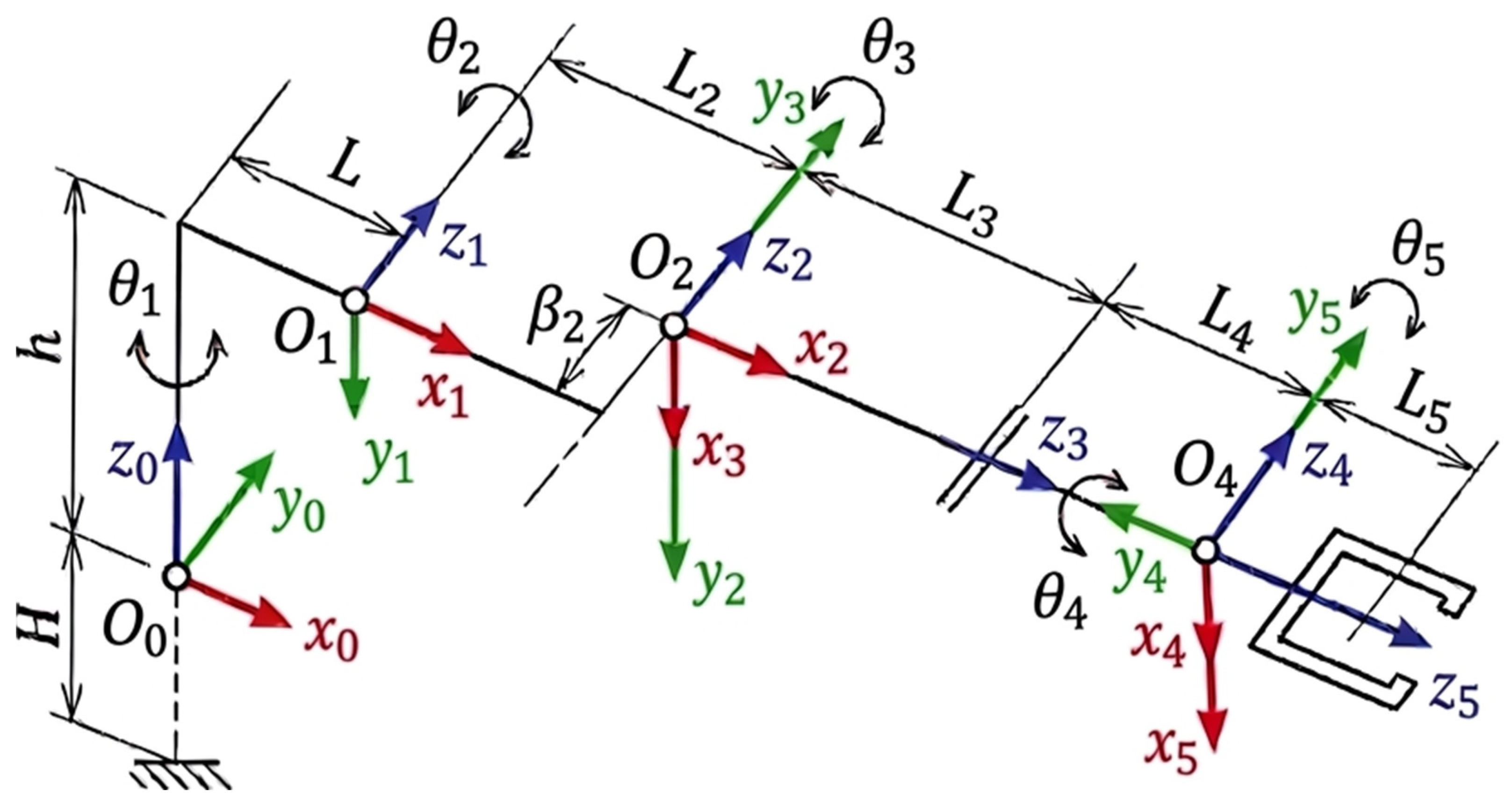
Frames for the 5R manipulator are specified in
Figure 1 in compliance with Denavit–Hartenberg convention. The basis vector
is chosen to be perpendicular to the basis vector
and to intersect it. An additive color model (RGB color model) is used to map the axes: red for the x-axis, green for the y-axis, and blue for the z-axis (
Figure 1).
D-H parameters—rotation
, offset
di, displacement
and twist
—are specified in
Table 1 according to robot geometry and the kinematical chain in
Figure 1.
The geometrical parameters for the robot are H = 56 mm, h = 32 mm, L = 10 mm, L2 = 119 mm, L3 = 88 mm, L4 = 33 mm, L5 = 104 mm, and = 19 mm.
Transformation matrices for every two consecutive frames, based on D-H parameters, are
The homogeneous transformation matrix of the frame attached to the central point of the wrist relative to the base is described by Equation (6), where:
The orientation matrix for the gripper is formed by three 3 × 1 column vectors—approach vector , sliding vector and normal vector .
Adding the length of the end effector by multiplying
and
results in the following position vector
.
The components of the position vector are:
2.2. Hardware Part of the Manipulator
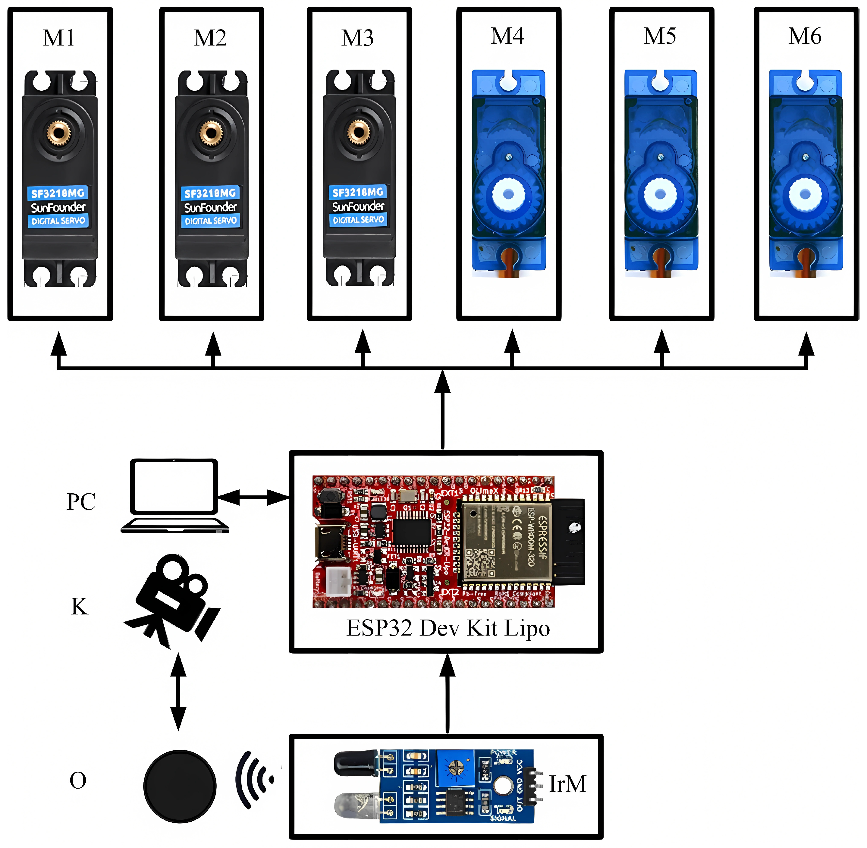
The embedded control system that will be used for the project must be familiar, accessible, and cheap, with a sufficient number of pins to achieve the desired goals. At this stage, the choice of the control part is reduced to two platforms: Arduino (Uno, Nano) and ESP32. On the one hand, Nano is a very cheap solution (4 euros) with dimensions the same as an integrated circuit, but has a limitation in terms of pins. On the other hand, ESP32 offers additional capabilities for wireless communication. A block diagram of the hardware part of the manipulator is shown in
Figure 2. The Arduino (Uno, Nano) and ESP32 Dev Kit Lipo development board, purchased from the sales network of Olimex, Plovdiv, Bulgaria was chosen to be the basis for the robot control.
It offers excellent features, such as a microcontroller with a 32-bit core, low price (8 euros), a large number of pins, built-in Wi-Fi and Bluetooth modules, and sufficient memory. The board offers options for upgrading the project at a later stage. The main disadvantage compared to other boards of this type, such as Arduino, is the lower voltage (3 volts) of the digital inputs. Three of the motors (M1, M2, M3) are of the TD-8120MG type with metal gears and high torque, and the remaining three are the SG90 micro servo motor. At the moment, no driver is used to control the servo motors, and the power supply is provided by a source of stable current (4A) and voltage (5V). A camera (C) is used to monitor and record the robot’s manipulations. The object (O) is a sphere with a diameter of 40 mm. An infrared module (IrM) of the HW201 type is used to detect the object. The software is written to the microcontroller from a personal computer (PC) via USB. The SG90 micro servo motor and infrared module (IrM) of the HW201 were purchased from specialized electronics stores in Plovdiv, Bulgaria.
2.3. Software Part of the Manipulator
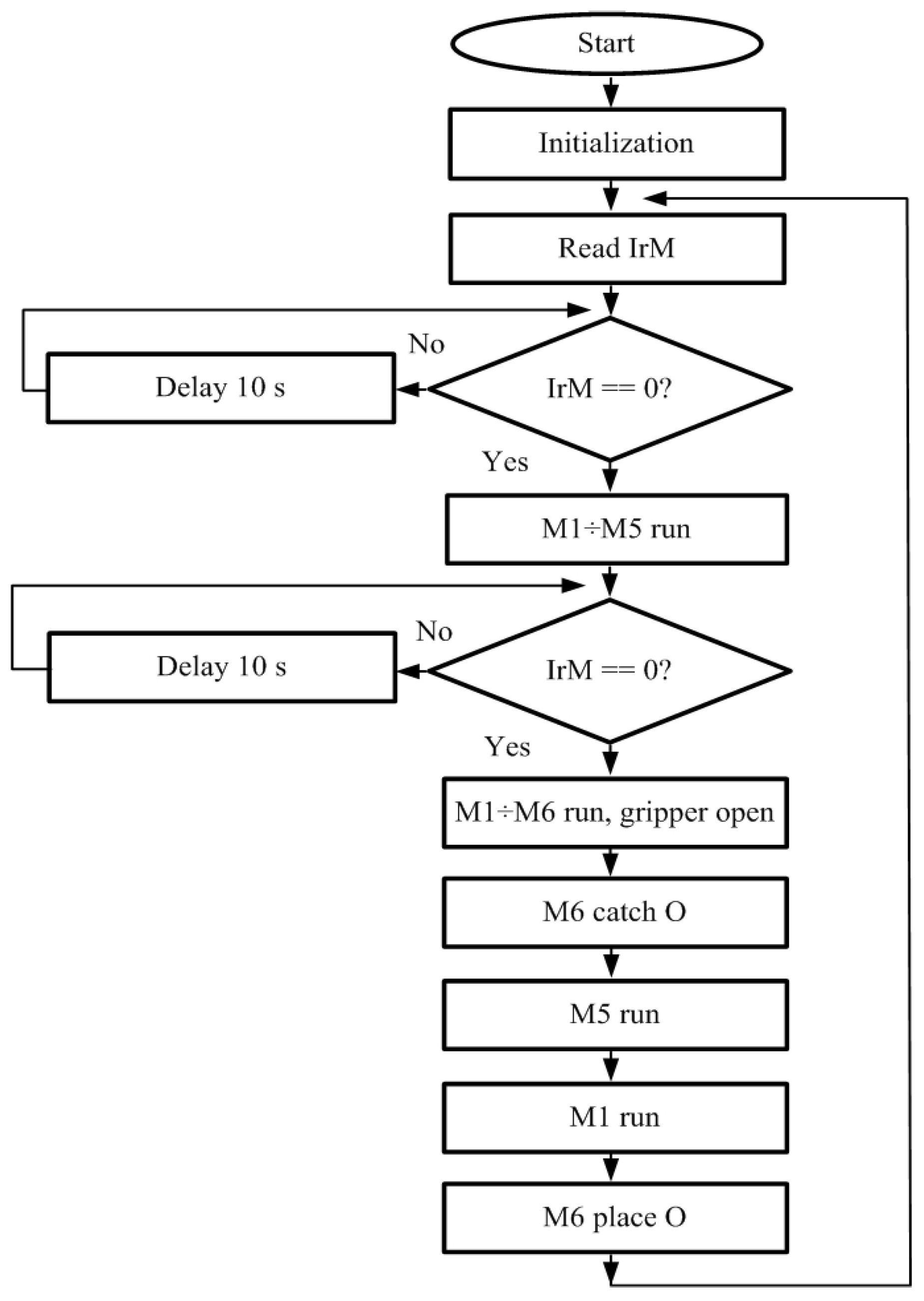
Figure 3 shows a block diagram of the program for the hardware part. After the start and initial setup of the robot, it checks for the presence of an object via IrM at a certain point in space. If there is no object, it waits 10 s, and if there is a low level (object present), the motors (M1÷M5) are started to rotate the manipulator to a set position. This is not the exact position of the object, after which a new check is made for the presence of the object. If there is no object, the program returns to the previous step. If there is an object, the motors are additionally started with a smaller step for accurate positioning to the object, with the M6 motor opening the jaws. After the object is gripped by the jaws, the object is lifted by M5, and M1 is started to rotate the manipulator to a certain position. After that, M6 opens the jaws and releases the object.
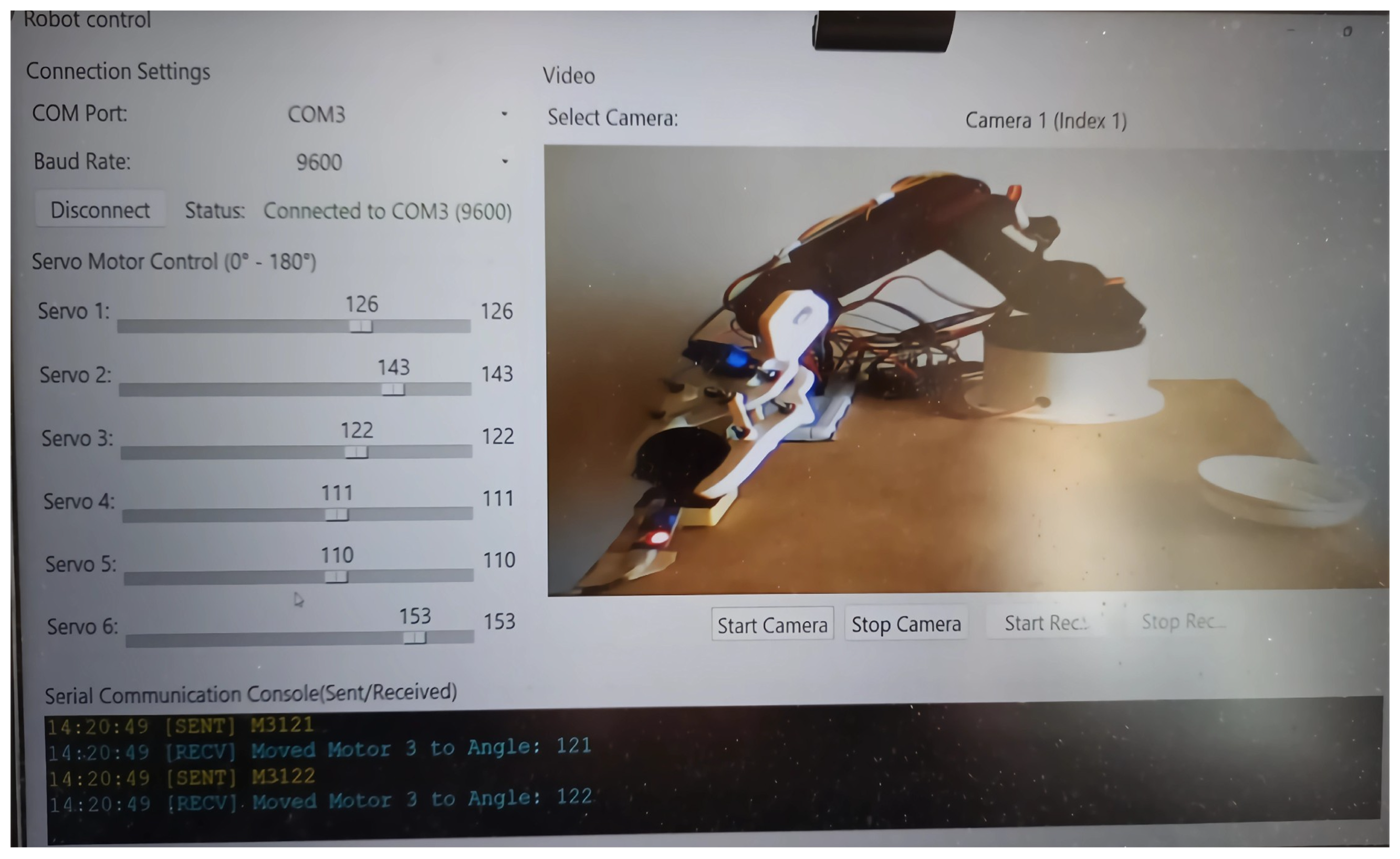
Additionally, a Python 3.14 application has been developed for visualization from different angles and manual operation mode.
3. Results and Discussion
The robot parts are printed with PLA Devil Design material weighing 150 g and a fill factor of 20%. The approximate price of the robot is about $100, with the most expensive being the high-torque servo motors ($13). The material for production is PLA Devil Design, 1.75 mm purchased from Grema 3D, Ruse, Bulgaria. The price will be lower when producing more units of the manipulator. The maximum length to which the robot can extend and grip a workpiece is 30 cm forward and 35 cm in height. The last degree of freedom allows the gripper to be positioned at 90 degrees relative to the base. This allows the manipulator flexibility that is missing in robots with fewer degrees of freedom. The biggest difficulty in assembling the manipulator is assembling the gripper. The end effector of the manipulator is designed based on a gear system. At a later stage, a simpler design of this part will be sought. After the manipulator is assembled, adjustment is performed in order to reach the minimum and maximum rotation position of each motor. This is the range in which the motor operates, and if the wrong position is set, the gears in the servo may be damaged or fall out. Another option for protection is a mechanical limit switch placed in an appropriate position, as well as current protection. Measuring the current through each motor will prevent its damage, which may be from overload or a mechanical problem. This will increase the price, but there will be no danger of further damage to the motors. In this case, they have no protection and this will be the subject of a subsequent upgrade of the project.
A Python 3.14 application has been created to visualize the manual and automatic modes of the robot.
Figure 4 shows a view of the application. The rotation angle of each motor from 0 to 180 degrees can be set using six software sliders. The value of the motor rotation angle is displayed in the console, and an image from an activated camera is visualized on the screen. Currently, two cameras can be used, but there is a possibility to add more. The selection of any camera is carried out from a drop-down menu, and its operation is carried out with the “Start Camera” and “Stop Camera” buttons below the screen. The application offers the possibility of video recording using the “Start Recording” and “Stop Recording” buttons. A test of the Python 3.14 application in manual mode was performed in order to verify the functional capabilities of the robot.
The data are summarized in
Table 2. To check the operating range of the motors, a step of one degree is set using the software sliders. From the data, it can be concluded that the operating range of each motor is individual. The construction of the robot is consistent and the weight of each unit affects the previous one.
The movement of the M3 motor is limited by the design of the second link, in the front of which M4 is placed. Currently, there is no protection of the motors when reaching the end position, which in the real machine would prevent jamming and damage to the motor. A kinematic analysis of the robot has been carried out. The following dependencies have been obtained for determining the position of the end link (gripper) in space depending on the angles of rotation of the joints:
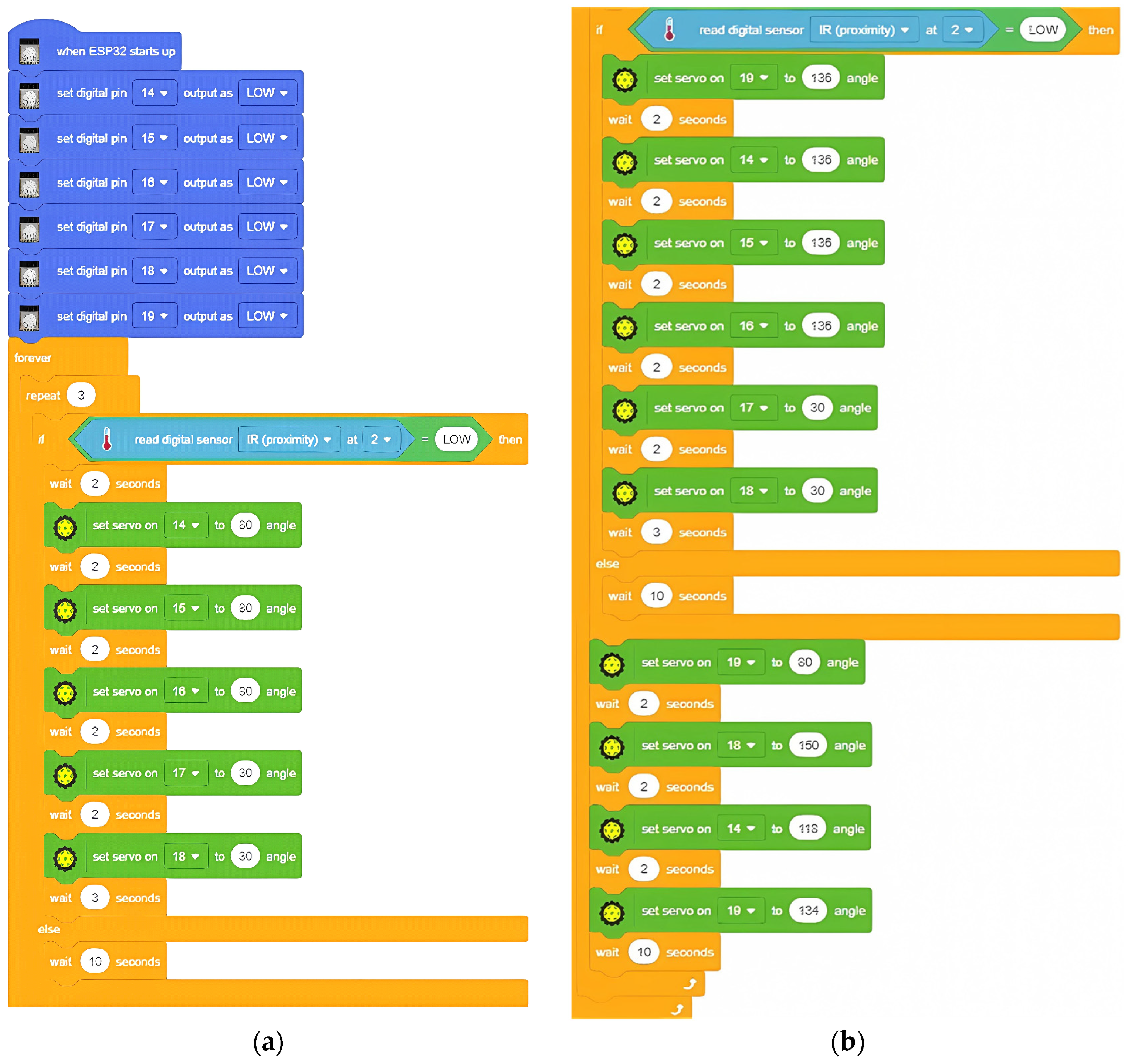
The robot is controlled using block programming in the PictoBlox 9.1.0 development environment. Block programming is similar to Scratch and is becoming increasingly popular. Many educational robots on the market support block programming in addition to the high-level programming languages C++ and Python 3.14.
Figure 5 shows the program created in this platform based on the flowchart in
Figure 3. The program in
Figure 5 is divided into two parts, as
b is continuous of
a.
The development environment used supports the most commonly used Arduino boards (Uno, Mega, Nano, ESP32). When choosing a specific type of board, different blocks are added to the environment depending on its capabilities. The code is visual and clear, and for this reason it is widely used in STEM robotics education to under-stand the principles of control. After each motor’s movement, a 2 s wait is initiated, after which the program execution continues.
4. Conclusions
This work presents the development of a low-cost robotic arm with five degrees of freedom, implemented using 3D-printing technology and controlled by an ESP32 microcontroller. The system includes the integration of a mechanical structure, embedded hardware components and control software, which allows the implementation of basic manipulation tasks of the “pick and place” type.
The performed kinematic analysis, based on the Denavit–Hartenberg method, provides a formalized basis for describing the manipulator’s movement and creates prerequisites for the future development of more complex control algorithms. The developed control system demonstrates stable operation and sufficient flexibility to perform basic tasks, while allowing easy modification and expansion of functionality.
The obtained results confirm that the use of 3D printing and affordable hardware platforms is an effective approach for creating robotic systems suitable for both training and experimental engineering research. The proposed solution is distinguished by good adaptability, low cost and the possibility of integration with various software environments.
Future developments of the research can include expanding the functionality of the manipulator by implementing sensor systems and feedback, developing more advanced control algorithms, introducing additional control (including based on artificial intelligence), and performing experimental research on the accuracy, repeatability and dynamic characteristics of the system in different operating modes.
Author Contributions
Conceptualization, N.K., Y.M. and A.N.; methodology, N.K.; software, N.K.; validation, Y.M. and V.M.; formal analysis, Y.M.; investigation, M.T.; resources, N.K.; data curation, Y.M.; writing—original draft preparation, M.S.; writing—review and editing, M.S. and M.T.; visualization, N.K.; supervision, M.T.; project administration, M.S.; funding acquisition, V.M. All authors have read and agreed to the published version of the manuscript.
Funding
This research was supported by project “Robotic System with Artificial Intelligence Elements for the Management of Technological Objects and Processes in the Food Industry,” Contract No. 09/25-H, dated 23 July 2025, funded by the Science Fund of the University of Food Technology, Plovdiv, Bulgaria.
Institutional Review Board Statement
Not applicable.
Informed Consent Statement
Not applicable.
Data Availability Statement
The data supporting the findings of this study are available from the authors upon reasonable request.
Conflicts of Interest
The authors declare no conflicts of interest.
References
- Sharkawy, A.N.; Nazzal, J.M. Design and manufacturing using 3D printing technology of a 5-DOF manipulator for industrial tasks. Int. J. Robot. Control Syst. 2024, 4, 893–909. [Google Scholar] [CrossRef] [Scilit]
- Herbst, F.; Suppelt, S.; Schäfer, N.; Chadda, R.; Kupnik, M. HELENE: Six-axis accessible open-source 3D-printed robotic armfor research and education. Hardware 2025, 3, 7. [Google Scholar] [CrossRef] [Scilit]
- Varbanov, I.; Paunski, Y.; Angelov, G.; Valchkova, N.; Zahariev, R. Latency and link speed for service robot control over mobile networks. In Proceedings of the 5th International Conference on Communications, Information, Electronic and Energy Systems (CIEES), Veliko Tarnovo, Bulgaria, 20–22 November 2024; pp. 1–4. [Google Scholar]
- Komitov, G.; Mitkov, I.; Kehayov, E. 3D Model of the Mechanical Part of a Sensor System for Collecting Data in an Agricultural Robot in a Catia Environment. In Proceedings of the 4th International Conference on Communications, Information, Electronic and Energy Systems (CIEES), Plovdiv, Bulgaria, 23–25 November 2023; pp. 1–4. [Google Scholar]
- Munir, M.T.; Jamwal, P.K.; Li, B.; Carter, S.; Hussain, S. Revolutionising engineering pedagogy: The role of 3D printing in modern engineering education. Innov. Educ. Teach. Int. 2025, 62, 575–593. [Google Scholar] [CrossRef] [Scilit]
- Loukatos, D.; Sideris, N.; Kyrtopoulos, I.-V.; Xanthopoulos, G.; Arvanitis, K.G. A Low-Cost Perception Improvement of an Electromechanical Gripper for Non-Destructive Fruit Harvesting. Eng. Proc. 2025, 104, 41. [Google Scholar] [CrossRef] [Scilit]
- Anchev, A.; Georgieva, T.; Ivanov, A. Experimental Comparison of Standard and Trajectories Movement Algorithm using Intelligent Camera. In Proceedings of the 4th International Conference on Communications, Information, Electronic and Energy Systems (CIEES), Plovdiv, Bulgaria, 23–25 November 2023; pp. 1–6. [Google Scholar] [CrossRef] [Scilit]
- Nenov, T.R.; Evstatiev, B.I.; Kadirova, S.Y. A Remote Lab for Experimental Study of DC Motors. In Proceedings of the 18th Conference on Electrical Machines, Drives and Power Systems (ELMA), Varna, Bulgaria, 29 June–1 July 2023; pp. 1–4. [Google Scholar] [CrossRef] [Scilit]
- Mitre, T.L. TARA: A low-cost 3D-printed robotic arm for accessible robotics education. arXiv 2025, arXiv:2509.01043. [Google Scholar] [CrossRef] [Scilit]
- Chebly, G.; Little, S.; Perera, N.; Abedeen, A.; Suzuki, K.; Kim, D. Strong, accurate, and low-cost robot manipulator. arXiv 2025, arXiv:2507.15693. [Google Scholar] [CrossRef] [Scilit]
- Habra, M.Y.; Canturk, İ. Development of a 4-dof low-cost robotic arm with integrated control systems and 3D-printed mechanical design for educational purposes. Int. J. 3D Print. Technol. Digit. Ind. 2025, 9, 612–623. [Google Scholar] [CrossRef] [Scilit]
- Ciungan, D.-A.; Mîș, E.-O.; Rusu, D.-Ș.; Bratosin, I.-A.; Popovici, A.-F.; Popovici, R.; Goga, N.; Goga, M.; Pomană, L.-N.; Bordea, C.-A.; et al. Enhancing IoT Education Through Hybrid Robotic Arm Integration: A Quantitative and Qualitative Student Experience Study. Appl. Sci. 2025, 15, 10537. [Google Scholar] [CrossRef] [Scilit]
- Balbuena, J.; Sinche, J.; Quiroz, D.; Arce, D.; Villota, E. PlatROB: An open-source, modular, and low-cost hardware platform for mobile robotics and AI education. HardwareX 2026, 25, e00747. [Google Scholar] [CrossRef] [Scilit] [PubMed]
- Vega, J.; Pérez, V. G-ARM: An open-source and low-cost robotic arm integrated with ROS2 for educational purposes. Multimed. Tools Appl. 2025, 84, 40683–40705. [Google Scholar] [CrossRef] [Scilit]
- Penev, A.; Dimov, D.; Kralchev, D. Open hybrid system for geometrical modeling. In Proceedings of the International Conference SAER 2003, Varna, Bulgaria, 19–21 September 2003; pp. 131–135. [Google Scholar]
| Disclaimer/Publisher’s Note: The statements, opinions and data contained in all publications are solely those of the individual author(s) and contributor(s) and not of MDPI and/or the editor(s). MDPI and/or the editor(s) disclaim responsibility for any injury to people or property resulting from any ideas, methods, instructions or products referred to in the content. |



 ,
,