Proceeding Paper

Cyclic Response of Aluminium SHS Beams: Experiments and Numerical Simulation †

1
Department of Civil Engineering, University of Salerno, Via Giovanni Via Giovanni Paolo II, 132, 84043 Fisciano, Italy
2
Department of Engineering, Telematic University Pegaso, Centro Direzionale Isola F2, 80132 Naples, Italy
*
Author to whom correspondence should be addressed.
Presented at the 16th International Aluminium Conference (INALCO 2026), Trondheim, Norway, 10–12 June 2026.
Eng. Proc. 2026, 151(1), 20; https://doi.org/10.3390/engproc2026151020
Published: 28 July 2026
(This article belongs to the Proceedings of The 16th International Aluminium Conference)

Abstract

This work presents an experimental and numerical investigation on the cyclic behaviour of square hollow section (SHS) beams made of 6060-T6 aluminium alloy subjected to non-uniform cyclic bending. Eight specimens with width-to-thickness ratios ranging from 18 to 48 were tested under a three-point cyclic bending protocol. The work provides relevant experimental findings, including moment-chord rotation curves, the number of cycles to local buckling onset, failure modes, and energy dissipation capacity. Additionally, a numerical model was created implementing a damage model to predict the progressive degradation and failure mechanism of the beams. Finally, the reliability of the Finite Element model was assessed by direct comparison of the results with the experimental data.

1. Introduction

In the last few decades, significant growth has been seen in the use of aluminium alloys in structural engineering. Applications for these alloys have been found in lightweight roofing, movable bridges, offshore structures, and the reinforcement of existing constructions [1,2,3,4]. The main advantages of this material are widely recognised such as (i) high strength-to-weight ratio, (ii) good ductility and workability, (iii) high corrosion resistance and (iv) favourable life-cycle costs, making it an attractive option from an environmental and circular economy standpoint [5]. Compared to steel, aluminium is approximately two thirds lighter and allows the manufacturing of complex shapes through processes such as extrusion, proving particularly advantageous in contexts where weight reduction is a primary design concern. However, aluminium members are characterised by an elastic modulus equal to about one third of that of steel, making them more sensitive to local and global instability phenomena, which must be carefully accounted for in design.
The structural specificities of aluminium alloys, including strain hardening behaviour, well described by the Ramberg–Osgood constitutive law, and susceptibility to local buckling, have prompted extensive research aimed at improving the prediction of the inelastic response of members subjected to compression and bending [6,7,8,9,10,11,12]. Current European design provisions are provided in EN 1999-1-1 (Eurocode 9) [13], which mainly cover static loading conditions, without any specific guidelines for the seismic design. Growing interest has emerged within the scientific community regarding the use of aluminium in seismic design, particularly as a dissipative element in shear walls, shear-link frames, and hysteretic dampers [14,15]. In response to this need, specific seismic design rules for aluminium structures have been introduced for the first time in the draft version of second generation of Eurocode 8 (prEN 1998-1-2), specifically in Chapter 15 [16]. Nevertheless, current research on the response of aluminium alloy members to cyclic loading is still very limited, especially when compared to that of steel. In order to make progress in closing this knowledge gap, the present work investigates the hysteretic behaviour of aluminium square hollow section beams subjected to non-uniform cyclic bending load. In addition an FE model is developed and validated through comparison with experimental results, demonstrating the capability to account for the local buckling and cyclic damage.

2. Experimental Programme

2.1. Test Specimen and Setup

The experimental programme involved 8 square hollow section beams fabricated from the 6060-T6 aluminium alloy, subjected to non-uniform cyclic bending load. Table 1 summarises the geometry of the tested specimens, where L is the tested length, B is the plate outer nominal width, t f u and t f l are the upper and lower plate thickness (flanges) of the cross-section respectively and t w 1 and t w 2 are the left and right plate thicknesses representing the webs. Moreover the sectional class calculated according to EN 1999-1-1 is depicted in the same table. It can be noted that most of the tested specimens belong to Class 4, meaning that hysteretic response will be strongly affected by local instability phenomena in the elastic range.
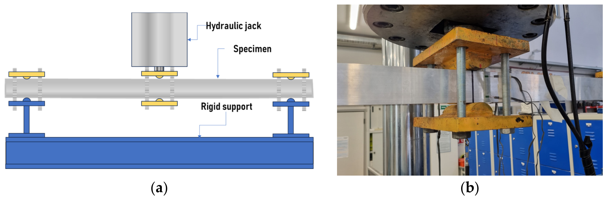
A three-point cyclic flexural load under displacement control was performed for each specimen. The test equipment and the loading protocol adopted are represented in Figure 1 and Table 2 respectively, where n c is the number of cycles, θ is the target chord rotation, δ is the vertical displacement at midspan and v is the speed rate of the tests. It is noteworthy that due to the absence of a specific cyclic loading protocol for aluminium beams, in this study the provisions for cyclic qualification of Beam-to-Column connection defined in AISC 341-16 are taken as reference. In particular the number of cycles ( n c ) and the associated chord rotation ( θ ) are provided.

2.2. Experimental Test Results

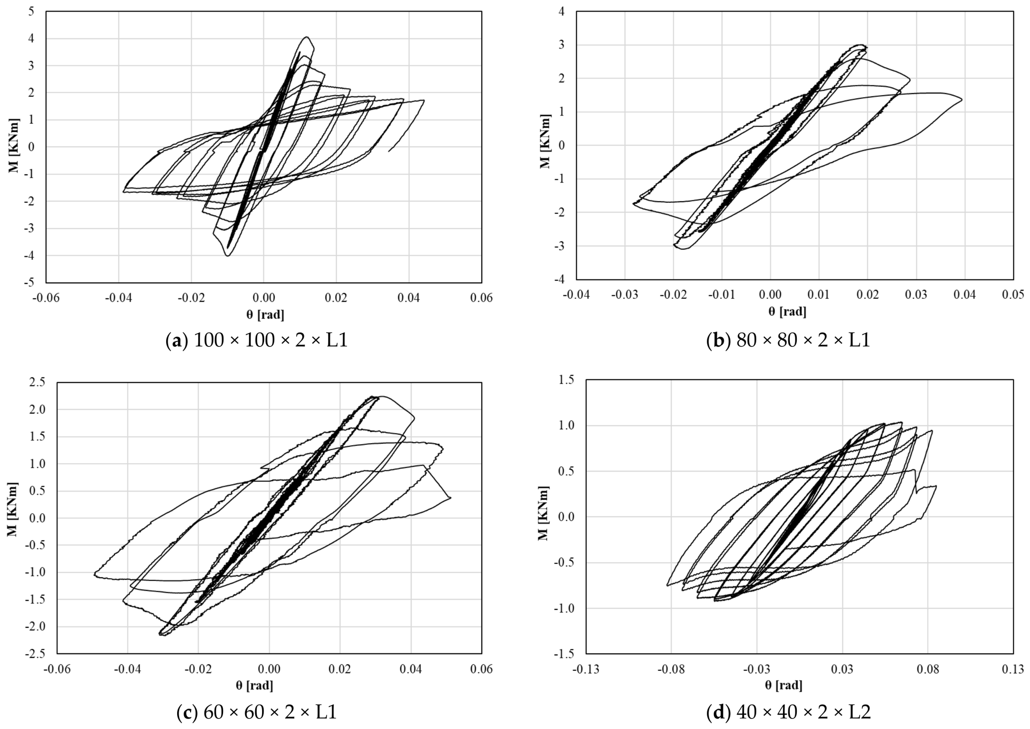
This section presents the main experimental findings. Figure 2 presents the cyclic response of the beams with L = 1300 mm as moment-chord rotation curves, where the moment M and the rotation θ , are calculated as:
M = F L / 4 θ = 2 δ / L
By observing the curves, it is clear that 100 × 100 × 2 specimen, the one with the greatest slenderness parameter b/t = 48 (where b = B − 2tw), is the most affected by the instability phenomena; in fact local buckling initiates in the elastic range at a chord rotation equal to 0.01 rad, preventing the development of the complete flexural capacity of the cross-section. Conversely, the 40 × 40 × 2 specimen, belonging to Class 2, exhibits large and stable cycles, with the complete development of strain hardening effects and the occurrence of local buckling only after reaching a chord rotation equal to 0.058 rad. For the 80 × 80 × 2 and 60 × 60 × 2 specimens, despite both sections being classified as Class 4, the onset of local buckling is considerably more delayed compared to the 100 × 100 × 2 specimen. In particular, for the 60 × 60 × 2 specimen, local buckling initiates at a chord rotation equal to 0.028 rad. Regarding the absolute maximum resistance it is evident that when cross-section dimensions increase, the peak load also increases. Table 3 summarises the main parameters obtained from the tests, including the maximum flexural capacity M u . m a x , the chord rotation θ u . m a x corresponding to M u . m a x , the number of cycles before the occurrence of local buckling n c . b and the total plastic dissipated energy E .

3. Numerical Simulation

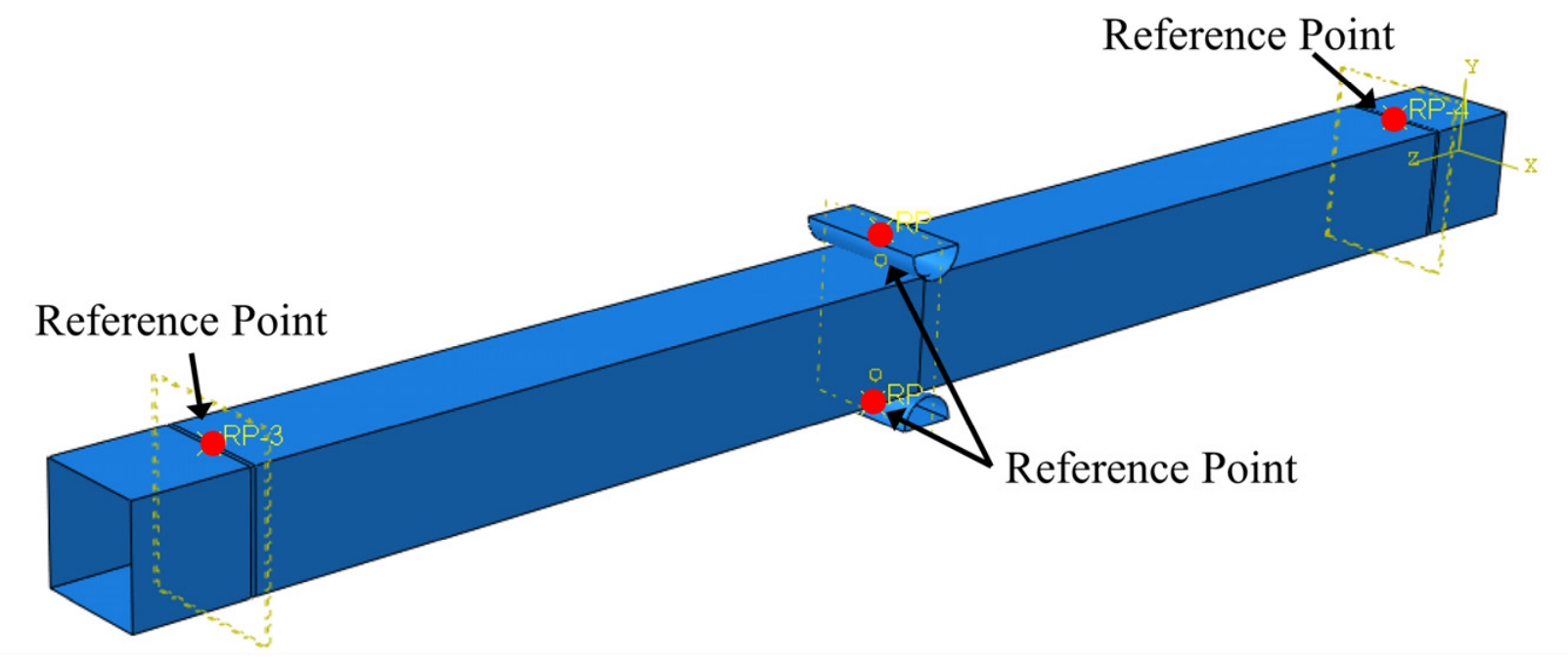
In this section the Finite Element model developed in ABAQUS/CAE 2020 [17] is described. Considering the small thickness of the section, shell elements with four nodes and reduced integration (S4R) have been adopted to model the beams, while the load application elements (half cylinder) were modelled as infinitely rigid elements. Lateral constraints considered as hinges were defined by coupling the pertinent section portion to reference points located at the supports as shown in Figure 3. Surface-to-surface contact has been adopted to simulate the contact behaviour between the beam and the half cylinder. The initial geometric imperfections have been considered by adopting the measured values of the thickness of the plates constituting the cross-section. - Regarding mechanical imperfections, it is well documented that [18] the extrusion process produces negligible residual stresses; therefore, they were not explicitly modelled.
In order to simulate accurately the non-linear cyclic behaviour and the cyclic softening highlighted in the experimental tests an appropriate material law and a ductile damage criterion have been adopted.

3.1. Material Law

For each beam the measured elastic modulus E and the average conventional yield strength f 0.2 of the four plates that compose the section have been adopted for defining the elastic branch. In order to simulate the behaviour under cyclic loading accounting for the non-linear hardening and the Bauschinger effect, a combined hardening model associated with the Mises yield surface was adopted but considering only the nonlinear kinematic part (domain translation component). The nonlinear behaviour has been expressed as the linear sum of three back-stress functions, which describe the translation of the yield surface in stress space. Each back-stress is described by two parameters: Ck, representing the initial kinematic hardening moduli and γk, representing the rate at which the kinematic hardening moduli decrease with increasing plastic deformation. The parameters were defined by the fitting process of the true stress-plastic strain curves, which were derived from the tensile coupon test extracted from the tested beams.

3.2. Damage

To define the initiation of the damage in the numerical simulation, the Johnson–Cook ductile criterion has been adopted [19]. If the strain rate and thermal effect are neglected, the equivalent plastic strain at the onset of damage ε ¯ 0   p l described by the model, is expressed as:
ε ¯ 0   p l = D 1 + D 2 e D 3 σ *
where σ * is the stress triaxiality and D1, D2 and D3 are failure parameters to be calibrated through experimental test on notched tensile specimens. According to Bridgman’s theory [20] the initial value of stress triaxiality in the cross-section of round-bar specimen as a function of the geometry of the notch can be derived as:
σ * = 1 3 + ln 1 + a 2 ρ
where a is the cross-sectional radius in the notch and ρ the radius of curvature of the notch. As in the present study only un-notched specimens with σ * = + 1 / 3 have been tested, the complete stress triaxiality range behaviour was captured by exploiting damage curves obtained in [20]. This allowed the calibration of the Johnson–Cook failure parameters presented in Table 4.
After damage initiation, the material stiffness degrades progressively following a specific damage evolution law until the overall damage variable reaches the value D = 1 and the mesh element is removed. It should be noted that the damage evolution law is defined in terms of equivalent plastic displacement δ ¯ p l which is dependent on the equivalent plastic strain at failure ε ¯ f   p l and the characteristic length Lc of the element. For this study, a linear damage evolution law has been adopted, and different values of displacement at failure δ ¯ f   p l for each beams were calibrated based on the experimental results.

4. FEM Results and Comparison with Experiments

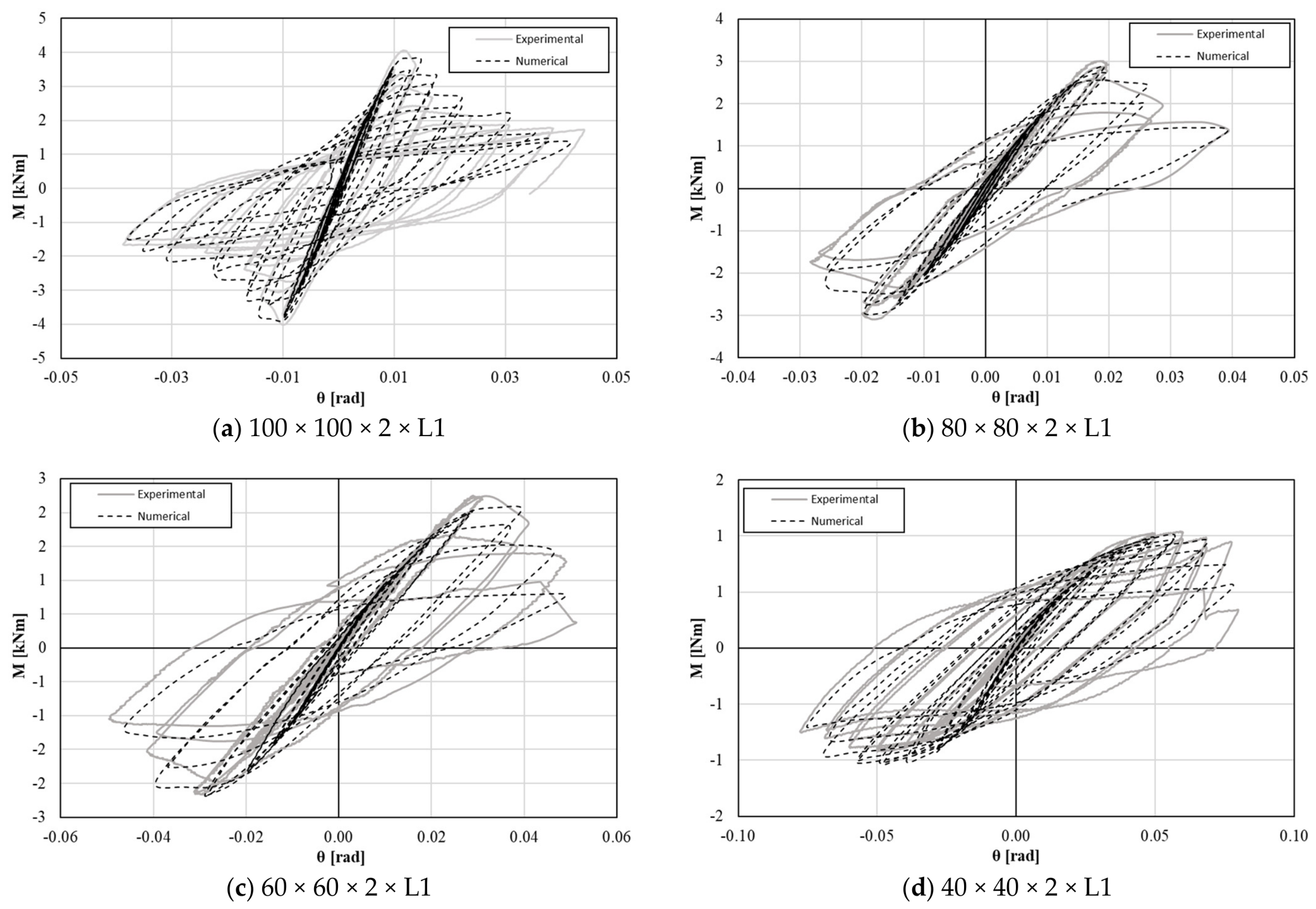
Figure 4 presents the comparison between numerical and experimental hysteretic response in the M - θ domain for the beams with L = 1.3 m. From a graphical overview, it is clear that the calibrated numerical model is capable of simulating quite accurately the hysteretic behaviour of the tested beams in terms of initial stiffness, peak load and post-buckling response. In addition, the progressive cyclic stiffness degradation due to local buckling and damage evolution is accurately replicated, confirming that a linear damage accumulation law can be assumed with good approximation. The only notable difference is observed in the 100 × 100 × 2 specimen during the last cycles, where the numerical model exhibits a different behaviour in the unloading phase for positive rotations.

5. Conclusions

In this study the first experimental campaign aimed to evaluate the response of height SHS beams fabricated from 6060-T6 aluminium alloy and loaded under non-uniform cyclic bending is described. The slenderness parameters b/t of tested beams range from 18 to 48. The tests reveal that the 40 × 40 × 2 specimen is the only one capable of exploiting its maximum flexural capacity with local buckling phenomena occurring only beyond 0.05 rad. Despite the good rotational capacity and ductile behaviour of the 40 × 40 × 2 section, considering the new Chapter 15 of the second generation of Eurocode 8, it could not be used in the dissipative zone in bending, since only Class 1 sections are permitted. This demonstrates that the actual simplified methodology of cross-section classification currently in use in Europe may limit a more efficient use of aluminium as a structural material and thus further experimental investigation is required. Regarding the other sections, 100 × 100 × 2, 80 × 80 × 2, and 60 × 60 × 2, all exhibited local buckling phenomena that prevented the full exploitation of the material’s strain hardening capacity. Finally, a Finite Element model was developed, showing that an accurate plasticity material model combined with the implementation of a ductile damage model can accurately predict the response of this type of material under cyclic loading. Following the validation of the numerical model, parametric analyses are planned to expand the available experimental dataset, with the objective of determining simplified analytical formulas capable of predicting the cyclic behaviour of plastic hinges in 6060-T6 aluminium alloy hollow sections.

Author Contributions

Conceptualisation, V.P. and A.P.; methodology, V.P. and E.N.; software, P.T. and F.P.; validation, V.P., E.N. and A.P.; formal analysis, F.P.; investigation, A.P.; resources, V.P.; data curation, A.P. and F.P.; writing—original draft preparation, A.P., F.P. and P.T.; writing—review and editing, A.P. and V.P.; visualisation, F.P.; supervision, E.N.; project administration, V.P.; funding acquisition, V.P. All authors have read and agreed to the published version of the manuscript.

Funding

This research received no external funding.

Institutional Review Board Statement

Not applicable.

Informed Consent Statement

Not applicable.

Data Availability Statement

All available data has been included in the article.

Conflicts of Interest

The authors declare no conflicts of interest.

References

  1. Mazzolani, F.M. Structural Application of Aluminium in Civil Engineering. Struct. Eng. Int. 2006, 16, 280–285. [Google Scholar] [CrossRef] [Scilit]
  2. Soetens, F.; Snijder, H.H. New Challenges for Aluminium Structures: An Introduction. Struct. Eng. Int. 2006, 16, 280. [Google Scholar] [CrossRef] [Scilit]
  3. Mazzolani, F.M. Aluminium Structures in Refurbishment: Case of the Real Ferdinando Bridge on Garigliano River. Struct. Eng. Int. 2006, 16, 352–355. [Google Scholar] [CrossRef] [Scilit]
  4. Dokšanović, T.; Džeba, I.; Markulak, D. Applications of aluminium alloys in civil engineering. Teh. Vjesn. 2017, 24, 1609–1618. [Google Scholar] [CrossRef] [Scilit]
  5. Efthymiou, E.; Cöcen, Ö.N.; Ermolli, S.R. Sustainable Aluminium Systems. Sustainability 2010, 2, 3100–3109. [Google Scholar] [CrossRef] [Scilit]
  6. Faella, C.; Mazzolani, F.M.; Piluso, V.; Rizzano, G. Local Buckling of Aluminium Members: Testing and Classification. J. Struct. Eng. 2000, 126, 353–360. [Google Scholar] [CrossRef] [Scilit]
  7. Su, M.N.; Young, B.; Gardner, L. Deformation-based design of aluminum alloy beams. Eng. Struct. 2014, 80, 339–349. [Google Scholar] [CrossRef] [Scilit]
  8. Piluso, V.; Pisapia, A.; Rizzano, G. Local buckling of aluminium channels under uniform compression: Theoretical analysis and experimental tests. Thin-Walled Struct. 2022, 179, 10951. [Google Scholar] [CrossRef] [Scilit]
  9. Piluso, V.; Pisapia, A.; Nastri, E.; Montuori, R. Ultimate resistance and rotation capacity of low yielding high hardening aluminium alloy beams under non-uniform bending. Thin-Walled Struct. 2019, 135, 123–136. [Google Scholar] [CrossRef] [Scilit]
  10. Piluso, V.; Pisapia, A. Interactive Plastic Local Buckling of Box-shaped Aluminium Members under Uniform Compression. Thin-Walled Struct. 2021, 164, 107828. [Google Scholar] [CrossRef] [Scilit]
  11. Su, M.N.; Young, B.; Gardner, L. The continuous strength method for the design of aluminium alloy structural elements. Eng. Struct. 2016, 122, 338–348. [Google Scholar] [CrossRef] [Scilit]
  12. EN1999-1-1; Eurocode 9: Design of Aluminium Structures—Part 1-1: General Structural Rules. CEN: Brussels, Belgium, 2007.
  13. Rai, D.C.; Wallace, B.J. Aluminium shear-links for enhanced seismic resistance. Earthq. Engng. Struct. Dyn. 1998, 27, 315–342. [Google Scholar] [CrossRef] [Scilit]
  14. De Matteis, G.; Brando, G.; Mazzolani, F.M. Hysteretic behaviour of bracing-type pure aluminium shear panels by experimental tests. Earthq. Engng. Struct. Dyn. 2011, 40, 1143–1162. [Google Scholar] [CrossRef] [Scilit]
  15. prEN1998-1-1; CEN/TC250/SC8. CEN: Brussels, Belgium, 2022.
  16. ABAQUS. Abaqus/Standard V. 2017, User’s Manual; Hibbit, Karlsson & Sorensen, Inc.: Pawtucket, RI, USA, 2020. [Google Scholar]
  17. Mazzolani, F.M. Aluminum Alloy Structures, 2nd ed.; E & FN Spon: London, UK, 1995. [Google Scholar]
  18. Johnson, G.R.; Cook, W.H. Fracture Characteristics of Three Metals Subjected to Various Strains, Strain Rates, Temperatures and Pressures. Eng. Fract. Mech. 1985, 21, 31–48. [Google Scholar] [CrossRef] [Scilit]
  19. Bridgman, P. Studies in Large Plastic Flow and Fracture, 2nd ed.; Harvard University Press: Cambridge, MA, USA, 1964. [Google Scholar]
  20. Mae, H.; Teng, X.; Bai, Y.; Wiezbicki, T. Calibration of Ductile Fracture Properties of Two Cast Aluminum Alloys. In Proceedings of the 13th International Conference on Experimental Mechanics, Alexandroupolis, Greece, 1–6 July 2007. [Google Scholar]
Figure 1. (a) Test equipment for cyclic load and (b) picture of the SHS 60 beam.
Engproc 151 00020 g001
Figure 2. Moment-chord rotation curve for L1300 specimen.
Engproc 151 00020 g002
Figure 3. Geometrical model of SHS 60_L1300 beam.
Engproc 151 00020 g003
Figure 4. Comparison between numerical and experimental curves.
Engproc 151 00020 g004
Table 1. Geometry of specimen.
L a b e l L [m]B [mm] t w 1 [mm] t w 2 [mm] t f u [mm] t f l [mm] C l a s s
S e c t i o n
40 × 40 × 2 × L21.0402.132.302.102.002
60 × 60 × 2 × L21.0602.032.032.002.034
80 × 80 × 2 × L21.0802.002.002.031.904
80 × 80 × 2 × L21.01002.132.002.302.334
40 × 40 × 2 × L11.3402.102.402.021.992
60 × 60 × 2 × L11.3602.162.102.062.134
80 × 80 × 2 × L11.3802.062.102.001.984
80 × 80 × 2 × L11.31002.132.002.302.334
Table 2. Loading protocol.
n c θ [mrad] L = 1000   m m L = 1300   m m
δ [mm] v [mm/s] δ [mm] v [mm/s]
63.751.880.082.440.10
652.500.103.250.13
67.53.750.154.880.20
4105.000.206.500.26
2157.500.309.750.39
22010.000.4013.000.52
23015.000.6019.500.78
24020.000.8026.001.04
25025.001.0032.501.30
26030.001.2039.001.56
27035.001.4045.501.82
28040.001.6052.002.08
Table 3. Main parameters of the tested beam.
Specimen M u . m a x [kNm] θ u . m a x [rad] n c . b [−] E   [ J ]
40 × 40 × 2 × L11.030.058331353
60 × 60 × 2 × L12.240.02829888
80 × 80 × 2 × L13.00.01826616
100 × 100 × 2 × L14.060.01231906
40 × 40 × 2 × L21.020.048311301
60 × 60 × 2 × L22.290.02327753
80 × 80 × 2 × L22.870.01425537
100 × 100 × 2 × L23.570.00922695
Table 4. Johnson–Cook failure parameters adopted in numerical model.
D 1 D 2 D 3
0.0251618
Disclaimer/Publisher’s Note: The statements, opinions and data contained in all publications are solely those of the individual author(s) and contributor(s) and not of MDPI and/or the editor(s). MDPI and/or the editor(s) disclaim responsibility for any injury to people or property resulting from any ideas, methods, instructions or products referred to in the content.